No. 483,294 – Spokeshave (Edward D. White) (1892)
[paiddownloads id=”487″]483294


UNITED STATES PATENT OFFICE.

_________________

EDWARD D. WHITE, OF HARTFORD, CONNECTICUT.

SPOKESHAVE.

_________________

SPECIFICATION forming part of Letters Patent No. 483,294, dated September 27, 1892.
Application filed January 22, 1892. Serial No. 418,975. (No model.)

_________________

To all whom it may concern:

Be it known that I, EDWARD D. WHITE, of Hartford, in the county of Hartford and State of Connecticut, have invented certain new and useful Improvements in Spokeshaves, of which the following is a full, clear, and exact description, whereby any one skilled in the art can make and use the same.

The special object of my invention is to provide a tool belonging to the class of spoke-shaves that shall be particularly adapted to cutting leather, although it is equally adapted for other uses; and to this end it consists of the details of the several parts making up the spokeshave as a whole and in their combination, as more particularly hereinafter described, and pointed out in the claims.

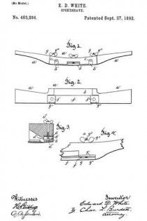
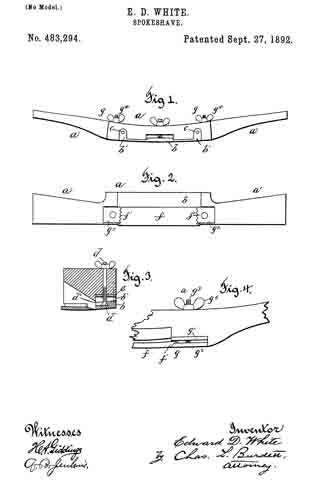
Referring to the drawings, Figure 1 is a detail front view of a spolreshave embodying my invention. Fig. 2 is a detail view of the under side of the spokeshave. Fig. 3 is a detail view, in cross-section, through the spokeshave, illustrating the method of supporting and adjusting the throat-piece. Fig. 4 is a detail rear view of a portion of a spokeshave embodying my invention.

In the accompanying drawings, the letter a denotes the body part of the spokeshave, made usually of wood and provided at the opposite ends with handles a’, by means of which the tool is held in working.

The letter b denotes a throat-piece located on the under side of the body part of the shave and connected to it by means of screws c, that pass through the upturned arms b’ at opposite ends of the throat-piece. These arms are preferably located in sockets formed in the body part of the shave and are secured by means of these screws or bolts, that pass through holes in the upper ends of the arms, the hole being slightly larger in diameter than the supporting bolt or screw in order to allow the throat-piece to have a swinging movement on such supports. In order to provide for this adjusting movement of the throat-piece, the edge of which extends lengthwise of the blade and immediately in front thereof, the head d’ of a bolt d engages a socket d2, formed in the upper part of the throat-piece, the bolt having a threaded portion extending through the nut e, that is secured to the body part of this spokeshave. The upper end of this bolt is provided with a thumb-nut or suitable handle, by means of which the bolt may be rotated in such manner as to change the position of the front edge of the throat-piece, so as to regulate the width of the opening between the cutting-edge of the blade and the edge of the throat-piece. The blade f is removable and adjustable, and it is secured to the body part of the spokeshave by means of clamp devices, that are located at the opposite ends of the blade. These clamp devices g comprise a bed-piece g’, against which the back part of the blade rests, and which may be formed by the surface of the spokeshave when such part is of metal, but when of wood are preferably formed by pieces of metal located in a suitable socket, and a holding part g2, that is connected by means of a bolt g3 with a nut g4, that fits on the threaded upper end of the bolt that extends through the body of the shave. The ends f’ of the blade proper are beveled and are made irregular, preferably by serrating such edges or forming a number of teeth that are engaged by corresponding teeth formed in the beveled edge of the clamp-plate. These serrations or indentations have a double function, taken in connection with the bevel of the edge: first, to provide for the adjustment of the blade in the direction of the throat-piece, and, next, to enable the blade to be removed and renewed after grinding or replaced by a new blade. The indentations or serrations are made sufficiently close together to permit of any needed degree of forward adjustment of the blade to compensate for the wear of the cutting-edge.

The cutting-blade in my improved spoke-shave is both renewable and adjustable and is clamped by positive clamping means formed to prevent the blade from slipping when the spokeshave is in use, and the blade being of a single piece, without any projecting parts at right angles to the blade, which are needed in old forms of spokeshave, may be ground on any grindstone without regard to its width, and such a blade is therefore readily sharpened. Two or more blades may be provided, so that in case the spokeshave is being used at a distance from a shop where such repairs may be made a new and sharp one may be readily inserted in the place of one that by use has become broken or dulled.

A particular advantage of the adjustable throat-piece is that the spokeshave can be adjusted to out a shaving of any desired thickness, and the throat-piece may also be so adjusted as to project beyond the cutting-edge, and serves as a guard for it. When the throat has become clogged by shavings, it is readily cleared by simply enlarging the opening by a simple turn of the adjustable bolt.

I claim as my invention —

1. In a spokeshave, in combination with the body part, the adjustable throat-piece comprising a flat portion, the upturned arms, the fastening means whereby the throat-piece is loosely secured to the body part of the spokeshave, and the clamp-screw whereby the throat-piece is adjusted, the removable blade having the beveled and serrated ends, and the clamp devices having the corresponding beveled and serrated edges, all substantially as described.

2. In a spokeshave, in combination with the body part, an adjustable throat-piece comprising a flat portion, the upturned arms having sockets, the bolt or like part smaller in diameter than said sockets for loosely securing the throat-piece to the body portion of the spokeshave, the clamp-screw whereby the throat-piece is adjusted, the removable blade having the beveled and serrated ends, and the clamp devices having the corresponding beveled and serrated edges, all substantially as described.

3. In a spokeshave, in combination with the body part, the adjustable throat-piece comprising a flat portion, the upturned arms, the fastening means whereby the throat-piece is loosely secured to the body part of the spokeshave, the adjusting-screw having its lower end engaging a socket in the throat-piece and a threaded portion engaging the body of the spokeshave, whereby said adjusting-screw has a vertical movement, the removable blade having the beveled and serrated ends, and the clamp device having the corresponding beveled and serrated edges, all substantially as described.

4. In a spokeshave, in combination with the body part, the adjustable throat-piece comprising a flat portion, the upturned arms, the fastening means whereby the throat-piece is loosely secured to the body part of the spokeshave, the adjusting-screw having its lower end engaging a socket in the throat-piece and a threaded portion engaging a nut located on the body of the spokeshave, the nut, the means for turning the adjusting-screw, the removable blade having the beveled and serrated ends, and the clamp devices having the corresponding beveled and serrated edges, all substantially as described.

EDWARD D. WHITE.

Witnesses:
HARRY S. POWERS,
EDWARD J. PEARSON.

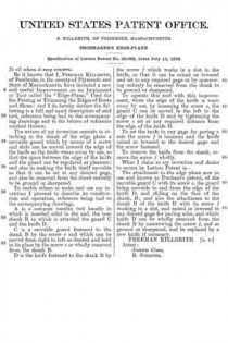
No. 249,097 – Shave (Henry P. Roberts) (1881)

[paiddownloads id=”316″]249097


UNITED STATES PATENT OFFICE.

_________________

HENRY P. ROBERTS, OF JAMESTOWN, N. Y., ASSIGNOR OF THREE-FOURTHS TO THE HORTON MANUFACTURING COMPANY, OF SAME PLACE.

SHAVE.

_________________

SPECIFICATION forming part of Letters Patent No. 249,097, dated November 1, 1881.
Application filed June 1, 1881. (No model.)

_________________

To all whom it may concern:

Be it known that I, HENRY P. ROBERTS, a citizen of the United States, residing at Jamestown, in the county of Chautauqua and State of New York, have invented certain new and useful Improvements in Shaves; and I do hereby declare that the following is a full, clear, and exact description of the invention, which will enable others skilled in the art to which it appertains to make and use the same, reference being had to the accompanying drawings, and to the letters of reference marked thereon, which form a part of this specification.

The object of this invention is to combine a gage or friction roller with a cutting edge or blade.

The principle of my invention can be shown in a heel-shave by which any of the ordinary-shaped heels may be operated upon, the tool adjusted to cut thin shavings of leather, and the shavings moved rapidly away from the knife-edge, to prevent clogging of the shavings-passage, and the tool can also be used upon wood as an ordinary spokeshave.

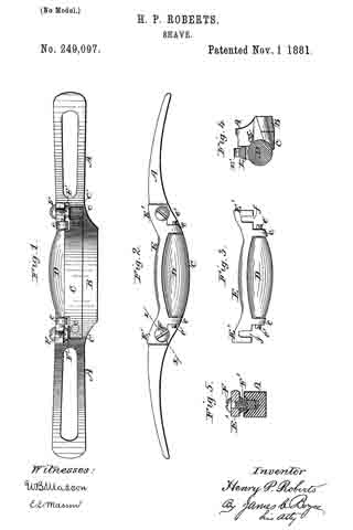
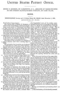
In the accompanying drawings, Figure 1 is a bottom view of a spoke or heel shave with my improvement thereon. Fig. 2 is a front view thereof. Fig. 3 is a view of the gage-roller and the frame thereof, detached. Fig. 4 is a transverse section through the middle of the roller, its supporting-frame, and the knife-blade, with its frame; and Fig. 5 is a section on line x x of Fig. 2.

The letter A represents the handle of the tool, which is curved at the center and recessed inwardly from its front edge, to receive the knife and gage-roller, the two parts of the handle being conneoted in one piece by the curved bridge B.

Immediately in front of the bridge is located the knife-blade C, curved to conform to the shape of the lower surface of the bridge, and secured to the handle by screws c. The cutting-edge of the knife is turned outwardly and projects somewhat forward of the shanks C’, by which said blade is attached to the handle.

Immediately above and partly in front of the edge of the knife is arranged a gage-roller, D, which corresponds with the shape of the knife, and in this case it tapers from its middle toward each end in such a manner that the longitudinal curve of its surface corresponds with the curve of the edge of the knife; but if it should be combined with a straight knife, it would be cylindrical in shape. This gage-roller D is mounted in an adjustable frame, E, between the downwardly-projecting lugs e, on which the roller is pivoted on screw-pivots e’. The ends E’ of the frame are provided with open slots f, through which pass screws F to secure said frame to the handle, the slots permitting either an upward or downward adjustment of the frame and roller, to bring said roller in such relation to the knife as to regulate the cut thereof as desired.

It will be observed that, owing to the curved shape of the knife, a very small portion of its edge may be brought in contact with the surface acted upon, if said surface is nearly flat, and that a heel of any of the ordinary shapes, either curved or straight, may be trimmed by the tool. The roller revolves as the tool advances, and the cut shavings coming in contact with the roller, their passage is facilitated through the opening between the roller and knife.

While the main functions of the gage-roller are to regulate the out of the knife, to remove friction and facilitate the passage of the shavings, it can be adjusted also to compensate for the wearing away of the edge of the knife. The adjustment can be made either by placing washers between the ends E’ of the roller-frame E and the frame of the blade C and removing these washers as fast as the blade wears away, or by supporting and clamping each end of the roller-frame between the heads of two screws, as shown in Figs. 1 and 5. In these figures, F’ represents the screws, inserted adjustably in the frame A. The flat head of said screws is hollow, and screw-tapped internally to receive the clamping-screws F, so that whatever may be the width of the blade C the roller D can be made to follow its edge, and the frame of said roller can be secured at each end.

I do not limit the use of my invention to heel or spoke shaves, as it is applicable to other cutting-instruments-for instance, carpenters’ planes.

Having now described my invention what I claim is —

1. The combination , with the handle, recessed as described, of the curved knife C, and the gage-roller tapered from its middle to its ends to conform to the curves of said knife, substantially as and for the purpose set forth.

2. The combination, with the recessed handle having the curved knife C secured thereto, of the roller D, arranged above said knife and mounted in an adjustable frame, E, substantially as described.

3. The combination with the handle, recessed as described, and having secured thereto the curved knife C, of the roller D, mounted in an adjustable frame, E, having the lugs e, between which the roller is pivoted, and between which the edge of the knife extends, substantially as described.

4. The combination of the centrally-curved handle, curved knife C, tapering roller D, and frame E, with adjustable hollow screws F’ and clamping-screws F, substantially as and for the purpose described.

In testimony that I claim the foregoing as my own I have hereto affixed my signature in presence of two witnesses.

HENRY P. ROBERTS.

Witnesses:
JAMES I. FOWLER,
WILLIAM K. VANDERGRIFT.

No. 138,625 – Improvement In Surfacing-Planes (George E. Franklin) (1873)

[paiddownloads id=”211″]138625


UNITED STATES PATENT OFFICE.

_________________

GEORGE E. FRANKLIN, OF NATICK, MASSACHUSETTS.

IMPROVEMENT IN SURFACING-PLANES.

_________________

Specification forming part of Letters Patent No. 138,625, dated May 6, 1873; application filed March 8, 1873.

_________________

To all whom it may concern:

Be it known that I, GEORGE E. FRANKLIN, of Natick, in the county of Middlesex and State of Massachusetts, have invented an Improvement in Surfacing-Planes; and I do hereby declare that the following, taken in connection with the drawing which accompanies and forms part of this specification, is a description of my invention sufficient to enable those skilled in the art to practice it.

In using dies for punching or cutting shoe soles and uppers, and other stock, it is customary to use blocks of wood with the end of the grain uppermost, the top surface being faced off for smoothness. As such a block becomes too much worn for practical use, it is cut down with an adz to a plane below the lowest depression worn by the dies, and is then surfaced off with a smoothing-plane. This method of surfacing a block is very slow and laborious, and does not result in procuring a uniform face.

My invention has reference to a method of surfacing such a block by means of a plane alone; and for this purpose I make a plane having a straight bottom face and a straight side face, and projecting through said adjacent faces, and adjacent to the angle of such faces, two cutters or cutting-edges, one edge being and cutting horizontally, and the other being vertical and cutting vertically, the cutting-edges being in the same vertical plane, right-angular to the side face of the tool, this side face having a gage to regulate the depth of cut of both cutters or bits. This plane is used by beginning at one side of the block and setting the gage to the depth to be cut, in order to reach the deepest depressions, and resting the gage upon the top of the block, with the vertical cutter against the side of the block. Then, as the plane is worked, the vertical cutter planes off the block, while the horizontal cutter joints or cuts across the grain, and smooths the top surface of the block, the plane being thus used until the block is planed across its whole face. It is in this construction of the surfacing-plane that my invention primarily consists.

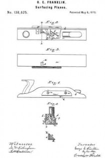
The drawing represents a tool embodying the invention.

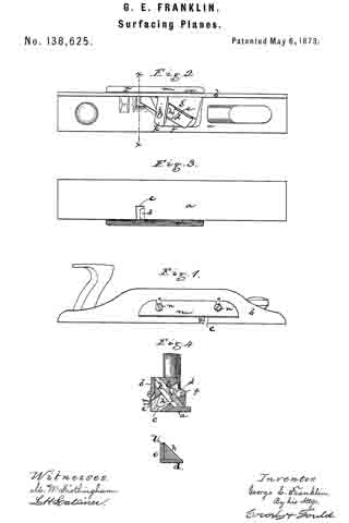
Figure 1 is a side view of the plane. Fig. 2 is a top view thereof. Fig. 3 is a bottom view. Fig. 4 is a cross-section on the line x x.

a denotes the bottom plate of the plane; b, an upright, extending from one edge of said plate; c, the throat through which the cutters or plane-bits extend and the chips escape. d e denote the two cutters, set at an angle to both plates a b, and at a right angle to each other, the cutter d resting upon a bed-piece, f, and its cutting-edge extending through the throat c, and so as to be in a horizontal plane just beyond the bottom face of the plate a, and the cutter e sitting edgewise on top of the cutter d, and with its inner face against a bed-piece, g, the cutter e also extending through the throat c, but its cutting-edge being vertical and standing just beyond the outer face of the upright b, the two cutting-edges standing, therefore, at a right angle and being in effect one cutting-edge, bent so as to be one part vertical and one part horizontal. The two cutters are held by an angular clamp, h, which is pressed down against the cutters by a screw, i, passing through a bar, k, and the clamp h has a shoulder, l, extending over the edge of the cutter e, so that not only are the two cutters forced against the bed-faces, but the cutter e is pressed against the cutter d, bringing their cutting-edges together and firmly securing them in position.

On the outer face of the upright b is fastened a gage, m, which, by screws n and slots o is made adjustable, and this gage determines the depth of cut of the two cutters.

As the tool is used, as before described, the edge d cuts across the grain, and the edge e with the grain, and by the action of the two cutters together the work is very rapidly effected, and the block uniformly surfaced or resurfaced.

I claim —

1. The surfacing-plane, formed with two cutters, d and e, having their edges in line and standing one in horizontal and the other in vertical position, combined with the gage m, on the vertical face of the plane, substantially as described.

2. In combination with the two cutters, the clamp h, for holding the cutters, substantially as shown and described.

3. The clamp, formed with the shoulder l, for pressing the cutter e down to the cutter d, substantially as shown and described.

GEO. E. FRANKLIN.

Witnesses:
FRANCIS GOULD,
M. W. FROTHINGHAM.

No. 74,757 – Improved Work-Trimmer For Boots And Shoes (A.V. Hill) (1868)

[paiddownloads id=”136″]74757


United States Patent Office.


A. V. HILL, OF LIMESTONE, NEW YORK.

Letters Patent No. 74,757, dated February 25, 1868; antedated February 12, 1868.
_________________

IMPROVED WORK-TRIMMER FOR BOOTS AND SHOES.

_________________

The Schedule referred to in these Letters Patent and making part of the same.

_________________

TO ALL WHOM IT MAY CONCERN:

Be it known that I, A. V. HILL, of Limestone, in the county of Cattarangus, and State of New York, have invented a new and improved Work-Trimmer; and I do hereby declare that the following is a full, clear, and exact description thereof, which will enable others skilled in the art to make and use the same, reference being had to the accompanying drawings, forming part of this specfiication.

This invention relates to an improved work-trimmer used chiefly in making ladies’ boots and shoes; and consists in a blade, of trapezoidal form, having a rectangular shank, bent at right angles to the blade, inserted in a slotted head. In the accompanying drawings —

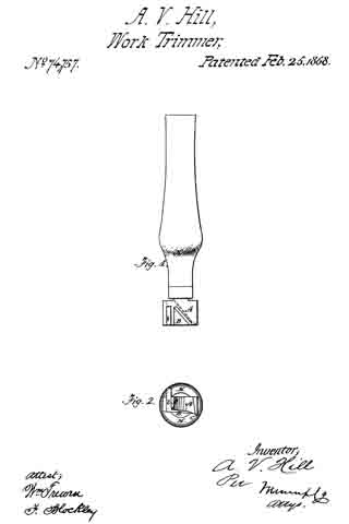
Figure 1 is a top view, and
Figure 2 an end view of my improved trimmer.

Similar letters of reference indicate like parts.

A is the slotted head set in the socket in handle H. The trapezoidal blade B is provided with a rectangular shank b, bent to it at right angles, and held adjustably in the slotted head A. A small lip at c serves as a guard.

In trimming work with any ordinary trimmer, the tool has to he worked from the body By applying the guard, c between the sole and upper, and drawing to the body, the blade pares the sole and cuts the welt-edge without any risk of cutting the upper, and with very much less exertion on the part of the workman.

What I claim as new, and desire to secure by Letters Patent, is —

1. The guard c, when applied to a work-trimmer, in manner and for the purposes substantially as described.

2. The blade B, fitted adjustably into a head, A, by the shank b, as herein set forth, and for the purposes substantially as described.

A. V. HILL.

Witnesses:
SHEP. L. VIBBARD,
FRANK COOK.

No. 70,894 – Improved Edge-Plane (John E. Plummer) (1867)

[paiddownloads id=”133″]70894


United States Patent Office.


JOHN E. PLUMMER, OF BINGHAMTON, NEW YORK.

Letters Patent No. 70,894, dated November 12, 1867.
_________________

IMPROVED EDGE-PLANE.

_________________

The Schedule referred to in these Letters Patent and making part of the same.

_________________

TO ALL WHOM IT MAY CONCERN:

Be it known that I, JOHN E. PLUMMER, of Binghamton, in the county of Broome, and State of New York, have invented a new and useful improvement on Edge-Planes for trimming the edges of boots and shoes; and I do hereby declare that the following is a full, clear, and exact description of the construction and operation of the same, reference being had to the accompanying drawings, making a part of this specification, in which —

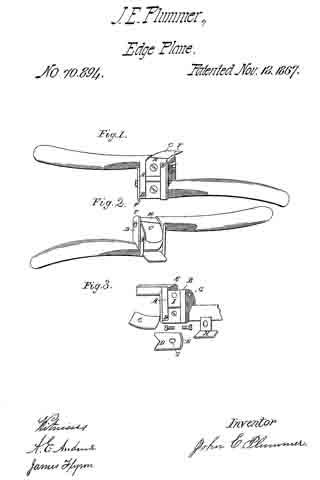
Figures 1 and 2 are perspective views, showing the concave and convex cutters.

Figure 3 represents the stock with the cutter-guard and throat detached.

Similar letters of reference indicate corresponding parts in each figure.

The object of my improvement is to construct a “reversible-edge plane” for trimming the soles of boots and shoes, which shall possess all the qualities requisite to accomplish the object with greater facility and ease, and at the same time to require less attention to keep it in order, than those in common use.

The nature of my invention consists in arranging a cutter on each side and in the centre of a stock, with a handle at each end. One of the cutters is designed for trimming the fore part of the sole, and the other for the “shank,” or that part under the instep, thereby combining in the same tool a cutter for the front or convex edges, and another for the “shank,” or concave edges of the sole.

It also consists in the simplicity of its construction and the adaptability of its form to accomplish the object designed.

I construct the stock A and the handles of cast brass, iron, or other suitable material. In the centre of the stock, I make projections B B on each side of the handles for the cutters C C, which are held in their places by the guard-plates D D, which are grooved to correspond with those in the stock, as represented in fig. 3, letters E E. The lower ends of said guard-plates are notched to fit into the shanks of the handles. The upper ends F F project above the face of the cutters, and are chamfered to work between the sole and the “uppers” of the boot or shoe, thereby protecting the work from injury. I then drill a hole, G, through the plate and into the stock, tap it, and enter the screw, but before turning it fully down, and while the guard-plate is still slightly loose, I enter the cutter into the grooves E E, and turn up the screw, which holds it securely in position. The throat H of the plane is made of steel, bent at right angles to the face, fitted between the guard and stock-back of the cutters, and the arm into a recess, I, held in place by a screw. The hole in the arm, through which said screw passes into the stock, is slightly elongated, for the purpose of graduating the shaving of the cutter. The stock A is chamfered down under the cutter and throat for the purpose of giving clearance to the shavings. The handles of the plane are slightly curved, and connect with the stock opposite, and their upper sides nearly flush with, the face of the plane or cutter on each side, so that when trimming the concave edges of the sole under the instep the opposite handle will not interfere with the work. One of the cutters is made straight for the purpose of trimming the convex edges of the sole. The other is curved to correspond to the concave edges under the instep.

The convex or fore part of the sole requires a “finer set” of the cutter than that of the shank or concave part, consequently manufacturers often use two instruments to accomplish the object rather than be constantly changing the “set” of the tool.

I am aware that there are many other arrangements for a similar purpose, but, so far as I know, there are none involving the combinations of my improvement. I therefore disclaim all interference with others, and confine myself to the novel features of my improvement.

Having thus described my invention, what I claim, and desire to secure by Letters Patent, is —

The construction and use of a “reversible-edge plane,” substantially as described and represented for the purpose set forth.

JOHN E. PLUMMER.

Witnesses:
A. E. ANDREWS,
JAMES FLYNN.

No. 20,882 – Shoemaker’s Edge Plane (Freeman Killbrith) (1858)

[paiddownloads id=”78″]20882


UNITED STATES PATENT OFFICE.

_________________

F. KILLBRITH, OF PEMBROKE, MASSACHUSETTS.

SHOEMAKER’S EDGE-PLANE.

_________________

Specification of Letters Patent No. 20,882, dated July 13, 1858.

_________________

To all whom it may concern:

Be it known that I, FREEMAN KILLBRITH, of Pembroke, in the county of Plymouth and State of Massachusetts, have invented a new and useful Improvement on an Implement or Tool called the “Edge-Plane,” Used for the Pairing or Trimming the Edges of Boots and Shoes; and I do hereby declare the following is a full and exact description of said tool, reference being had to the accompanying drawings and to the letters of reference marked thereon.

The nature of my invention consists in attaching to the shank of the edge plane a movable guard which by means of a screw and slide can be moved toward the edge of the knife as the knife wears away by use, so that the space between the edge of the knife and the guard can be regulated at pleasure; and also in making the knife itself movable so that it can be set at any desired gage, and also be removed from the shank entirely to be ground or sharpened.

To enable others to make and use my invention I proceed to describe its construction and operation, reference being had to the accompanying drawings.

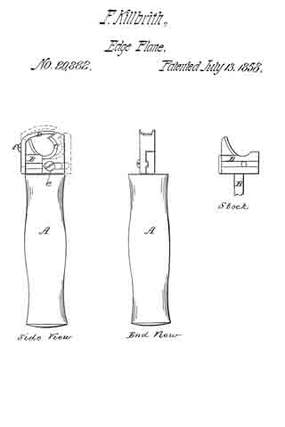
A is a common wooden tool handle in which is inserted solid in the end, the iron shank B to which is attached the guard C and the knife D.

C is a movable guard fastened to the shank B by the screw e and which can be moved from right to left as desired and held in its place by the screw e or wholly removed from the shank B.

D is the knife fastened to the shank B by I the screw f which works in a slot in the knife, so that it can be raised or lowered and set to any required gage or by unscrewing entirely be removed from the shank to be ground or sharpened.

To operate this tool with this improvement, when the edge of the knife is worn away by use, by loosening the screw e, the guard C can be moved to the left to the edge of the knife D and by tightening the screw e set at any required distance from the edge of the knife D.

To set the knife to any gage for paring a sole the screw f is loosened and the knife raised or lowered to the desired gage and the screw fastened.

To remove the knife from the shank, remove the screw f wholly.

What I claim as my invention and desire to secure by Letters Patent is —

The attachment to the edge plane now in use and known as Dunham’s patent, of the movable guard C with its screw e, the guard being movable to and from the edge of the knife D, and sliding on the face of the shank, B; and also the attachment to the shank B of the knife D with its screw f working in a slot, and raised or lowered to any desired gage for paring soles, and which knife D can be wholly removed from the shank B by unscrewing the screw f, and so ground or sharpened, and be replaced by a new knife if necessary.

FREEMAN KILLBRITH. [L. S.]

Attest:
JOSEPH COBB,
B. STREETER.