No. 1,112,399 – Bench Plane (Harvey M. Wood) (1914)
[paiddownloads id=”700″]1112399


UNITED STATES PATENT OFFICE.

_________________

HARVEY M. WOOD, OF LOS ANGELES, CALIFORNIA.

BENCH-PLANE.

_________________

1,112,399. Specification of Letters Patent. Patented Sept. 29, 1914.
Original application filed November 8, 1907. Serial No. 401,341. Divided and this application filed October
14, 1912. Serial No. 725,577.

_________________

To all whom it may concern:

Be it known that I, HARVEY M. WOOD, a citizen of the United States, residing at Los Angeles, in the county of Los Angeles and State of California, have invented a new and useful Bench-Plane, of which the following is a specification.

The object of this invention is to protect the cutting edge of the blade during the backward stroke of the plane and while standing idle on its sole, this result being attained by use of a heel-piece yieldingly projecting through and beyond the sole and serving to normally uphold the same above the table top.

This application is a division of my co-pending application for patent on bench plane, Serial No. 401,341, filed Nov. 8, 1907.

The accompanying drawings illustrate the invention.

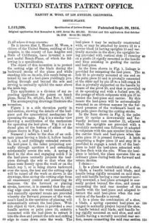
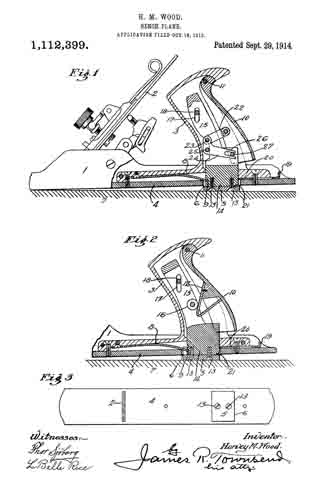
Figure 1 is a side elevation partly in mid-section, showing the details of the heel-piece and the symmetrical mechanism for operating the same. Fig. 2 is a similar view showing a modification of the mechanism for operating the heel-piece. Fig. 3 is a reduced plan of the bottom of either of the planes shown in Figs. 1 and 2.

Numeral 1 refers to the shoe of an ordinary plane having a blade 2, hollow handle 3, sole 4, and yieldingly extended retractible heel-piece 5, the latter projecting normally through aperture 6 and extending substantially across the sole. A spring 8, fixed to the shoe and engaging notch 9 in the heel-piece normally projects the heel-piece through the sole so that when the plane rests loosely upon the work or on the bench top 7, or is being drawn backward over the same, the heel and the cutting edge will be raised off the work as shown in the drawings, thus saving the cutting edge from all unnecessary contact and preserving its keenness. On the forward or planing stroke, however, it is essential that the cutting edge come onto the work immediately and manually operated means are provided whereby the forward pressure of the workman’s hand in the operation of planing, will automatically retract the heel-piece. With this object in view, there is provided a rear handle section or palm piece 10, suitably connected with the heel-piece to retract it into the shoe and permit the sole and cutting edge to come down onto the work. The heel-piece 5 may be unitarily constructed with, or may be attached by screws 13 to a carrier block 14 having uprights 15 and vertically movable in the shoe; the uprights being provided with vertical slots 17 running on a pintle 18 rigidly mounted in the handle and thus assisting in guiding the carrier and heel-piece.

In the form shown in Fig. 1, linkage is provided for retracting the heel-piece. The link 22 is pivotally mounted at one end on the palm piece 10 and is pivotally connected at the other end by pin 23 to a bell-crank 24 that is pivotally supported on the handle by means of the pivot 25, and that is provided at its operating end with a forked arm 26, the prongs of which cooperate with pin 27 to retract the heel-piece and carrier. By this means the heel-piece will be automatically retracted in an obvious manner by the forward pressure of the workman’s hand on the palm piece during the cutting stroke.

In the form shown in Fig. 2, the palm piece 10 carries a downwardly and forwardly inclined cam member 12, adjacent which the uprights are provided with a revolubly mounted cam follower 16 adapted to cooperate with the cam member 12 to raise the carrier block and heel-piece when the palm piece 10 is pressed forward. A latch comprising a finger piece 19 and stop 20 is provided to engage a notch 21 of the heel-piece to hold the heel-piece retracted with its face flush with the sole. When the heel-piece is latched, the plane operates like an ordinary plane during both the forward and return strokes.

I claim :–

1. In a plane the combination of a shoe, a blade, a handle behind said blade, said handle being rigidly mounted on said shoe, and said handle having a rear member movably mounted, a heel-piece arranged to normally project beyond the shoe, and means connecting the said rear member of the handle with the heel-piece and adapted to retract the said heel-piece when the rear section of the handle is moved.

2. In a plane the combination of a shoe, a blade, a spring operated heel-piece arranged to normally project beyond the shoe, a handle behind said blade, said handle being rigidly mounted on said shoe, and said handle having a movably mounted rear section, means connecting the said rear section of the handle with the heel-piece and adapted to retract the said heel-piece when the rear section of the handle is moved, and means for holding said heel-piece in its retracted position.

3. In a plane, the combination of a shoe, a blade, a hollow handle having a rear section pivotally mounted, a spring-operated heel-piece adapted to normally project beyond the shoe and mechanism in the hollow of the handle connecting the rear section of the handle with the heel-piece and adapted to retract the heelfpiece when the rear sec-
tion of the handle is moved.

4. In a plane the combination of a shoe, a blade, a hollow handle having a rear section pivotally mounted, a spring operated heel-piece adapted to normally project beyond the shoe, and link mechanism supported in the hollow of the handle and connecting the rear section of the handle with the heel-piece and adapted to retract the heel-piece when the rear section of the handle is moved.

5. In a plane the combination of a shoe, a blade, a hollow handle having a rear section pivotally mounted, a carrier riding in the hollow of the handle, a heel-piece mounted on the carrier and adapted to normally project through and beyond the shoe, and means in the hollow of the handle connecting the rear section of the handle with the carrier and adapted to retract the carrier and heel-piece by motion of the rear section of the handle.

6. In a plane the combination of a shoe, having a sole, a blade, a hollow handle having a rear section pivotally mounted, a heel-piece adapted to normally project beyond the sole, a bell-crank mounted within the handle and having a forked arm, a link connecting one arm of the bell-crank with the rear section of the handle, and a pin mounted on the heel-piece and cooperating with the forked arm of the bell-crank to be raised by the same.

7. In a plane, the combination with a shoe, a blade and a handle behind said blade, of a spring-operated heel-piece carried by said handle and arranged to lift the heel of the plane, and manually operated means for retracting said heel-piece.

8. In a plane, the combination with a shoe, a blade and a handle behind said blade, of a spring-operated heel-piece carried by said handle and arranged to lift the heel of the plane, means for retracting said heel-piece, and means for holding said heel-piece in its retracted position.

9. A plane comprising a sole, a handle fixed to said sole and provided with a movable palm-piece, and a heel piece operatably connected to the palm-piece and normally below the plane of the sole and adapted to be raised by movement of said palm-piece.

In testimony whereof, I have hereunto set my hand at Los Angeles, California, this 28th day of September 1912.

HARVEY M. WOOD.

In presence of —
JAMES R. TOWNSEND,
ROBERT A. STEPS.

_________________

Copies of this patent may be obtained for five cents each, by addressing the “Commissioner of Patents, Washington, D. C.”
_________________

No. 913,959 – Scraper (Noble Keller) (1909)

[paiddownloads id=”658″]913959


UNITED STATES PATENT OFFICE.

_________________

NOBLE KELLER, OF LOS ANGELES, CALIFORNIA.

SCRAPER.

_________________

913,959. Specification of Letters Patent. Patented March 2, 1909.
Application filed January 10, 1908. Serial No. 410,191.

_________________

To all whom it may concern:

Be it known that I, NOBLE KELLER, a citizen of the United States of America, residing at Los Angeles, in the county of Los Angeles, State of California, have invented a certain new and useful Scraper; and l do hereby declare the following to be a full, clear, and exact description of the invention, such as will enable others skilled in the art to which it appertains to make and use the same.

This invention relates to a scraper and has among other objects, to provide a tool of this description, of simple and cheap construction which shall be efficient and durable in use and wherein the cutting blade can be readily formed, without the use of tools, other than those usually possessed by the user of the device.

It is also an object to provide a scraper that can be worked close up to any projection perpendicular to the surface on which it is used.

Another object is to provide means for easily adjusting the scraper blade.

A further object is to provide a scraper of such form that it can be readily grasped and pressure applied thereto without fatiguing the hands of the operator.

Still another object is to provide a scraper in which the blade need not be removed to sharpen the same.

One form in which this invention may be embodied, is herein described and is illustrated in the accompanying sheet of drawings, in which —

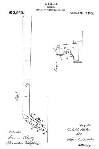
Figure 1 is a side elevation, and Fig. 2 is a rear elevation with portions broken away.

A handle 1 is fitted into a tubular socket 2, being retained therein by a pin or rivet 3. The rearward end of socket 2 has a downwardly deflected flattened portion 4, to which is attached by screws 5, a bolster 6, prefer-
ably formed of wood or other slightly yielding material. The lower portion of bolster 6 has a rabbet 7, which receives the upper portion of a blade 8, said blade being held frictionally between bolster 6 and a back plate 9, by means of bolt 10, which passes through a slot 9a in back plate 9, bolster 6, and downwardly deflected portion 4 of the handle, and has on its forward end, a nut 11. The sides of blade 8 may be beveled and sharpened in the same manner as the bottom of said blade. Blade 8 is preferably wider than back plate 9 and bolster 6. It may be formed of any convenient piece of sheet metal, such as an old saw blade, and there being no holes through it, it can readily be made with such tools as are usually carried by a wood worker.

The mode of operation of this invention is as follows: Handle 1 is grasped by one hand of the operator, while the other hand rests upon the top of bolster 6 and back plate 9. These parts being designed as shown, the hand rests easily upon this portion of the assembled tool and pressure may be applied without great fatigue to the operator.

The scraper is used by drawing it along the surface to be scraped, in the usual manner, as will be readily understood by those skilled in the art to which this invention appertains. In working close to vertical surfaces, the scraper may be laid upon its side and the ends of the blade used. In such use of the device, it will be readily understood that the handle extends away from the vertical surface, so that there is a sufficient clearance to enable the operator to manipulate the device conveniently. The blade 8 may be protruded, as it becomes worn, by striking on the upper sides of the projecting portions.

I claim:

1. A scraper comprising ahandle having a widened portion at the lower end thereof, a wooden bolster affixed to said portion, a back plate, said bolster and said plate suitably shaped to afford a hand-rest thereon when the same are assembled, a single bolt having a nut threaded thereon and passing through said plate, bolster, and widened portion of the handle, whereby the blade may be clamped between said bolster and said back plate.

2. A scraper comprising a handle, a metal tube affording a socket for said handle and having a flattened part bent at an angle to said socket, a wooden holster secured to said flattened part, said bolster shaped to afford a hand-rest thereon, and having a out-away portion to accommodate a blade, a slotted back plate, a single bolt having a nut threaded thereon and passing through said plate, bolster, and flattened part, whereby the blade may be clamped between the bolster and the back plate.

In testimony whereof, I have signed my name to this specification in the presence of two subscribing witnesses at Los Angeles county of Los Angeles, State of California this 31st day of December A. D., 1907.

NOBLE KELLER.

Witnesses:
ALEXANDER H. LIDDERS,
ANNA A. BALTZ.

No. 761,097 – Router-Plane (McCluer H. Parker) (1904)

[paiddownloads id=”603″]761097


UNITED STATES PATENT OFFICE.

_________________

McCLUER H. PARKER, OF LOS ANGELES, CALIFORNIA.

ROUTER-PLANE.

_________________

SPECIFICATION forming part of Letters Patent No. 761,097, dated May 31, 1904.
Application filed December 15, 1903. Serial No. 185,228. (No model.)

_________________

To all whom it may concern:

Be it known that I, McCLUER H. PARKER, a citizen of the United States, residing at Los Angeles, in the county of Los Angeles and State of California, have invented a new and useful Router-Plane, of which the following is a specification.

This invention relates to improvements in router-planes, and particularly to the adjusting and clamping of the cutting knife or bit.

The router-plane forming the present invention is particularly adapted for routing out seats for door butts or hinges and for cutting out for locks and strike-plates for the same. The plane is of value in cutting seats for other building hardware or material that requires inlaying.

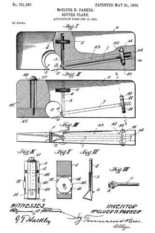
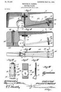
The accompanying drawings illustrate the invention, and referring to the same, Figure I is a side view of the router-plane with part of the stock broken away, showing the preferred construction. Fig. II is a side view of the router-plane, with part of the stock broken away, of another form. Fig. III is a bottom view of the form shown in Fig. I. Fig. IV is a view looking toward the nose of the form shown in Fig. II. Fig. V is a section on line V V, Fig. II. Fig. VI is a detail in perspective of the cutter or bit. Fig. VII isa detail in perspective of the clamping-rod.

1 designates the stock, which preferably tapers throughout its length, as shown, being wider at the heel than at the nose.

2 designates the cutting iron or bit, which is provided with a squared shank 3, the upper end of which is threaded, as at 4. The squared shank 3 is received by the stock of the plane in a square hole, and when in position the flat faces of the shank engage the flat faces of the hole to hold the shank from rotation relatively to the stock, the hole extending substantially at right angles to the bottom of the stock, and the cutting-iron 2 projects slightly downward and forward from the rear part of the throat 5 of the stock.

6 is a knurled thumb-nut which is mounted on the threaded shank 3, the stock 1 being slotted to receive the thumb-nut 6, and the edges of the nut protrude, as shown in Fig. III, so as to be readily grasped by the fingers in adjusting the cutting-iron.

7 is a clamping-bar having an eye 8, which is squared internally to receive the shank 3 of the cutting-iron, the shank 3 loosely fitting in the eye. The other end of the clamping-bar 7 is threaded, as at 9. and carries a locking-nut 10, the periphery of which is provided with square notches 11, which afford shoulders against which a tool may be struck-such, for instance, as a nail-set-to tighten the clamping-nut securely.

The stock 1 is slotted to receive the clamping-nut 10, and a washer 12 is provided within the stock 1, against which the locking-nut bears when screwed tight.

As shown, the clamping-bar extends from the rear of the throat 5 nearly to the heel of the plane and is inclined so as to bring the clamping-nut well above the bearing-face or bottom of the stock.

In the preferred form the stock 1 is made of a single piece of wood, and in order to put the clamping-bar in place in the stock the stock is drilled from the heel toward the throat with a hole of sufflcient diameter to allow of the passage through it of the eye 8, and a wooden sleeve 13, which is drilled centrally to receive the locking-bar 7, together with the locking-bar 7, is slipped into the hole in the stock from the heel, the sleeve before being inserted having had glue applied to its surface and the hole in the stock also having had glue applied to its surface, so that when the sleeve is in place in the stock the glue sets and the sleeve becomes practically part of the stock. A plug 14 is then glued into the stock to fill the end of the hole. Another form is shown in Fig. II, in which the lower part of the nose 15 is fastened to the upper part 16 by a tongue-and-groove joint, a tightening-screw 17 passing down through a wide slot 18 in the stock and screwing into the adjustable part 15. When the plane is of metal, it may preferably be constructed in this form and the sleeve 13 may be dispensed with, as the adjustable nose 15 may be moved forward or entirely removed from the stock to permit the locking-bar 7 to be slipped into place in the stock from the front, the hole in the stock in such cases being drilled of a size to just receive the shank of the locking-bar. After the locking-bar is in place the nose 15 may be fastened by tightening the screw 17.

When the lock-nut 10 is screwed up tight, it draws the locking-bar 7 to the rear and forces the shank 3 tightly against its squared seat in the stock 1, and the cutting-iron 2 is thus prevented from turning sidewise or from slipping up or down. To adjust the cutting-iron 2, the lock-nut 10 is loosened, which frees the shank 3, so that the nut 6 may be readily turned by the fingers to raise or lower the cutting-iron 2, and when it has been brought to the desired position the lock-nut 10 is again tightened, being easily forced very tightly into place by inserting a nail-set in a notch of the lock-nut and tapping the same.

I have found in practice that a plane constructed as herein set forth more than doubles the capacity of a mechanic in hinging doors and in doing other similar work and that the grade of work is also improved to a marked degree.

What I claim is —

1. A stock having a throat and having a hole extending substantially at right angles to the bottom of the stock, a cutting-iron having a shank lying in said hole, the shank and the part of the stock engaging therewith being formed with engaging parts to hold the shank from rotation, the shank having a threaded portion and a nut on the threaded portion for adjusting the cutting-iron, and means for clamping the shank.

2. A stock having a throat, and having a hole with a fiat face extending at substantially right angles to the bottom of the stock, a cutting-iron having a shank with a flat face lying in the hole, the shank having a threaded portion, and a nut on the threaded portion for adjusting the cutting-iron, and means for clamping the shank.

3. A stock having a throat, and having a hole with a flat face extending substantially at right angles to the bottom of the stock, a cutting-iron having a shank with a flat face lying in the hole, the shank having a threaded portion, a nut on the threaded portion for adjusting the cutting-iron, means for clamping the shank, and a clamping-bar having an eye through which the shank passes, the clamping-bar having a threaded portion, and a nut on the threaded portion for tightening the clamping-bar.

4. A stock, a cutting-iron having a squared shank threaded at one end, the shank lying within a square hole in the stock and substantially perpendicular to the bottom of the stock, a nut on the threaded portion of the shank within a slot in the stock, a clamping-bar having a squared eye which receives the shank of the cutting-iron, the clamping-bar having a threaded portion, and a nut on the threaded portion in a slot in the stock.

5. A stock, a cutting-iron having a squared shank threaded at one end, the shank lying within a square hole in the stock and substantially perpendicular to the bottom of the stock, a nut on the threaded portion of the shank within a slot in the stock, a clamping-bar having a squared eye which receives the shank of the cutting-iron, the clamping-bar having a threaded portion, and a nut on the threaded portion in a slot in the stock, said latter nut having a notched periphery.

6. A stock, a cutting-iron having a squared shank threaded at one end, the shank lying within a square hole in the stock and substantially perpendicular to the bottom of the stock, a nut on the threaded portion of the shank within a slot in the stock, a clamping-bar having a squared eye which receives the shank of the cutting-iron, the clamping-bar having a threaded portion, a nut on the threaded portion in a slot in the stock, said latter nut having a notched periphery, and a washer between the stock and the forward face of the latter nut.

In testimony whereof I have hereunto signed my name, in the presence of two subscribing witnesses, at Los Angeles, in the county of Los Angeles and State of California, this 7th day of December, 1903.

McCLUER H. PARKER.

Witnesses:
GEORGE T. HACKLEY,
JULIA TOWNSEND.

No. 755,587 – Scraping-Plane (William Ulses) (1904)

[paiddownloads id=”600″]755587


UNITED STATES PATENT OFFICE.

_________________

WILLIAM ULSES, OF LOS ANGELES, CALIFORNIA.

SCRAPlNG-PLANE.

_________________

SPECIFICATION forming part of Letters Patent No. 744,587, dated March 22, 1904.
Application filed October 29, 1903. Serial No. 179,070. (No model.)

_________________

To all whom it may concern:

Be it known that I, WILLIAM ULSES, a citizen of the United States, residing at Los Angeles, in the county of Los Angeles and State of California, have invented new and useful Improvements in Scraping-Planes, of which the following is a specification.

My invention relates to a plane for finishing surfaces made nearly smooth by the ordinary cutting-planes; and the object thereof is to provide a tool by means of which planed surfaces may be readily finished and with less danger of roughing the surface than if an ordinary scraper were used.

I accomplish this object by the scraping-planes described herein and illustrated in the accompanying drawings, in which —

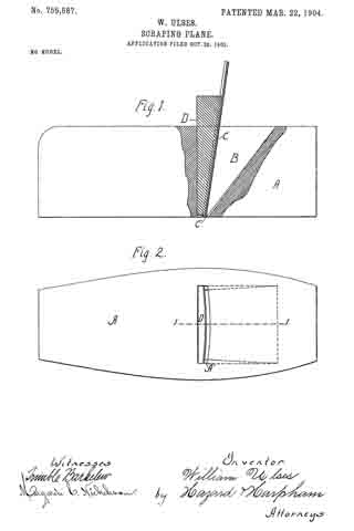
Figure 1 is a side elevation, with a portion in longitudinal central section taken on the line 1 1 of Fig. 2, of my scraping-plane. Fig. 2 is a view of the sole of my plane.

In the drawings, A is the stock, having a throat B for the reception of the plane-iron C and the binding-wedge D, which secures the plane-iron in the throat, binding it against abutments A’ on the sides of the throat. These abutments are shown in dotted lines in Fig. 1, the inner dotted line representing the top line of the abutments and the outer line representing the bottom line of the abutments. The tops of these abutments project forwardly of the bottoms, so that the top of the plane-iron is inclined forwardly, as shown in Fig. 1, when the wedge and iron are in place. I have found by practical test that an inclination of five-sixteenths of an inch in a stock of two inches in height produces very satisfactory results. The plane-iron is constructed, preferably, of a thin piece of tempered steel having the lower edges C’ thereof sharpened, as shown in Fig. 1, or otherwise formed into a scraping-surface. The front side of the binding-wedge forms the segment of a circle, and when the scraper-iron is secured in the stock it is bent into circular shape, as shown in Fig. 2, which causes the central portion thereof, by reason of the forward inclination of the top, to project through the stock a greater distance than the edges. With a scraper-iron two inches wide I have found that one-sixteenth of an inch produces a very satisfactory curvature and that a plane thus constructed will take out all the tool-marks and perfectly finish the surface. The curvature of the plane-iron caused by the wedge when in place in the stock prevents it from chattering. It will be observed that by this construction the central portion of the iron does its scraping in advance of the side portions, and thereby the danger of catching under the grain of the wood is lessened over that of using a scraper with a straight edge. It will also be observed that when the plane-iron is out of the stock its cutting edge is a perfect straight line and that it can thus be readily sharpened and that when put in place in the stock the edges follow at the rear of the center and are a little elevated above the center, thus preventing any marring of the surface upon which the plane is being used, the edges being preferably placed in the same plane as the sole of the stock.

Having described my invention, what I claim as new, and desire to secure by Letters Patent, is —

1. A scraping-plane comprising a stock having a throat with abutments on the sides and in the front portion thereof; a plane-iron composed of thin resilient metal and having its lower edges formed into a scraping-surface; a rigid binding-wedge of a length substantially equal to the height of the stock having a circular face adapted to pass into said throat back of the scraper-iron and bind said iron in said stock in a forwardly-projecting curved form.

2. A scraping-plane comprising a stock having a throat with abutments on the sides and in the front portion thereof, the tops of said abutments projecting forwardly of the bottom thereof; a plane-iron composed of thin resilient metal and having its lower edge formed into a scraping-surface; a rigid binding-wedge having a circular face adapted to pass into said throat back of the scraper-iron and bind said iron in place in the stock and to produce in said iron a forwardly-projecting curve.

ln witness that I claim the foregoing I have hereunto subscribed my name this 22d day of October, 1903.

WILLIAM ULSES.

Witnesses:
G. E. HARPHAM,
MARGARETÉ C. NICHOLSON.