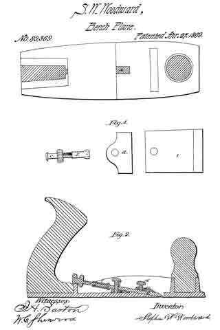
No. 603,832 – Block Or Smoothing Plane (Patrick Shea) (1898)

[paiddownloads id=”536″]603832


UNITED STATES PATENT OFFICE.

_________________

PATRICK SHEA, OF BOSTON, MASSACHUSETTS.

BLOCK OR SMOOTHING PLANE.

_________________

SPECIFICATION forming part of Letters Patent No. 603,832, dated May 10, 1898.
Application filed September 20, 1897. Serial No. 652,271. (No model.)

_________________

To all whom it may concern:

Be it known that I, PATRICK SHEA, of Boston, (Dorchester,) in the county of Suffolk and State of Massachusetts, have invented certain new and useful Improvements in Block or Smoothing Planes, of which the following is a description sufficiently full, clear, and exact to enable those skilled in the art to which it appertains or with which it is most nearly connected to make and use the same.

This invention relates to woodworkers’ planes generally, and particularly to metal block or smoothing planes.

It is the object of the invention to provide such improvements in articles of manufacture of the kind mentioned as will enable the bit or plane-iron to be supported at but a slight pitch or angle relatively to the sole or face of the plane, so as that it may better perform some functions than if it were set at the usual or common angle.

It is also the object of the invention to provide improved means for adjusting the plane-iron or bit, so that its depth of cut may be regulated with the utmost nicety.

It is, furthermore, the object of the invention to provide improved means for holding the plane-iron down upon its bed or seat, which means shall be simple in and economical of construction and serviceable and efficient in the highest degree.

To these ends my invention consists of the improvements which I will proceed to describe in detail, and then set forth with particularity in the appended claims.

Reference is to be had to the annexed drawings, and to the letters marked thereon, forming a part of this specification, the same letters designating the same parts or features, as the case may be, wherever they occur.

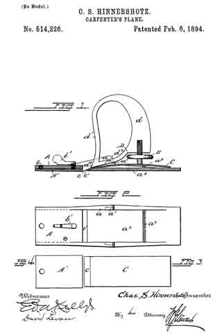
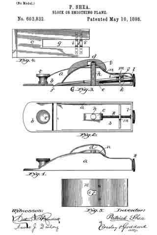
Of the drawings, Figure 1 is a side elevation of a metallic block-plane embodying my improvements. Fig. 2 is a plan view of the same, the bow-spring and toat being omitted. Fig. 3 is vertical longitudinal sectional view of the same. Fig. 4 is a plan view of the plane-bit detached. Fig. 5 is a bottom view of the bow-spring used to hold the bit down upon its bed and to serve also as the toat to the plane.

In the drawings, a designates the stock or frame of the plane, which, as herein shown, it is proposed to construct of metal, though it may be made of other material.

b is the sole or base, which is provided with sides or walls a and a rear wall or cross-
piece l.

c is the bit or plane-iron.

t is the “horn.”

d is the toat.

In carrying out my invention I provide a projection e on the upper side of the base G, provided with a vertical perforation to receive a stud h.

The bit is adapted to travel on inclined shevels or shoulders along the sides a of the stock, extending from the cross-piece l to the throat, and is formed in its longitudinal central rear portion with a slot g sufficiently wide to have the stud h and projection e operate therein when the bit is moved back and forth. Near the rear end of the bit there are two cross-bars i i’ secured to the bit, so as to bridge, as it were, the slot g and leave a space j between said cross-bars. It would serve my purpose just as well, however, to make the cross-bars i i’ an integral part of the bit.

k is a bit-adjusting screw threaded throughout nearly its length and arranged to turn in a hole formed in the vertical rear flange l of the bit-stock and at its inner end to be guided in a hole formed in the rearward part of the projection e. Neither of the said supports for the screw are screw-threaded, but are simply plain bearings for the latter.

Upon the screw k there is arranged a traveler on, having a screw-threaded hole formed therethrough to receive the shank of the screw k. The said traveler m extends up between the bridge-pieces i i’ of the bit in such a manner that when the screw is turned the traveler will be moved to and fro thereon, and as a consequence will move the bit longitudinally with it and adjust the bit in the mouth of the base of the plane, so as to make it take a deeper or shallower cut, as may be desired.

n designates the bow spring or holder, which is a piece of sheet metal bent in cross-section in the form of a bow, as is best represented in Fig. 3, so that its front end may rest upon the forward end of the bit and its rearward end bear upon the rear end of the same. Upon the bow-spring n, the toat d is supported, as shown.

In the central portion of the bow-spring there is formed a hole o, backward from which there extends a narrowed slot p, and in the upper end of the stud h, on opposite sides thereof, there are formed slots q, so that after the bit may have been put in place upon its bearings and properly connected with its adjusting means the bow-spring may be placed in position upon the bit, so that the upper end of the stud h, may extend through the hole o, and then by bearing down on the spring and moving it forward the sides of the slot p may take into the slots q of the stud and not only hold the spring in place, so that the toat or handle d may be employed in moving the plane, but so also as that the bow-spring may press and hold the bit down in its proper working position.

Inasmuch as in the operation of the plane the effort to move it back will be but slight and substantially all of the appreciable energy will be exerted forward, the bow-spring and toat will be held securely in place.

In addition to supporting the bit or plane-iron in position so as to render it most efficient in operation, as I have before described, my adjusting means for the bit have been found very efficient and simple, not liable to be disturbed in the usual operation of the plane, and effective in operating the bit to adjust it with the utmost nicety, and to do this in a manner better than is accomplished in planes as now commonly constructed. Furthermore, the means described for holding the bit in place by means of the bow-spring are exceedingly simple in and economical of construction, besides being effective in the highest degree.

Having thus explained the nature of the invention and described away of constructing and using the same, though without attempting to set forth all of the forms in which it may be made or all of the modes of its use, it is declared that what is claimed is —

1. A block or smoothing plane comprising in its construction a planer-iron or bit and bit-support; a bow-spring constructed to bear at its ends upon the forward and rear ends of the bit; and a headed stud, the bow-spring having a centrally-arranged keyhole-slot to engage the head of the stud as set forth.

2. In a device of the class described the combination with a walled base-piece having a projection on its upper face, of a headed stud mounted in the projection, a slotted bit suitably arranged on the stud, shoulders arranged diagonally of the side walls of the base and forming supports for the bit, a thumb-screw having bearings in said projection of the base and the rear wall, a screw-threaded traveler upon the thumb-screw, having connection with the bit and a bow-spring engaging the head of the stud and bearing at its ends upon the ends of the bit to secure the latter in position and provided with a toat upon its upper face.

In testimony whereof I have signed my name to this specification, in the presence of two subscribing witnesses, this 4th day of September, A. D. 1897.

PATRICK SHEA.

Witnesses:
ARTHUR W. CROSSLEY,
W. SHEA.

No. 514,226 – Carpenter’s Plane (Charles S. Hinnershotz) (1894)

[paiddownloads id=”501″]514226


UNITED STATES PATENT OFFICE.

_________________

CHARLES S. HINNERSHOTZ, OF READING, PENNSYLVANIA.

CARPENTER’S PLANE.

_________________

SPECIFICATION forming part of Letters Patent No. 514,226, dated February 6, 1894.
Application filed February 4, 1893. Serial No. 460,977. (No model.)

_________________

To all whom it may concern:

Be it known that I, CHARLES S. HINNERSHOTZ, a citizen of the United States, residing at Reading, in the county of Berks, State of Pennsylvania, have invented certain Improvements in Carpenters’ Planes, of which the following is a specification.

My invention relates more particularly to bench planes adapted to be constructed wholly or largely of metal.

The main objects of the invention are, first, to simplify the construction, and the setting and fastening of the bit, and second to make the operation more satisfactory.

The novel features of the invention are fully described in connection with the accompanying drawings and are specifically pointed out in the subjoined claims.

Figure 1 is a longitudinal section of a plane embodying my improvements. Fig. 2 is a plan view of the stock or bed. Figs. 3 and 4 are separate views of the bit-iron and of the adjustable spring plate which forms a portion of the sole.

The stock or bed A as shown is a casting, of which the main part of the base plate a3 forms the rear portion of the sole while the part of said plate forward of the mouth c’ is raised to a higher plane and has secured to its under side by means of a screw bolt b at its forward end a spring plate A’, the rear free end of which extends to the mouth c’ and is capable of being pressed downward from its normal position by means of an adjusting screw b’. This adjustable plate thus forms the forward portion of the sole.

The bit iron C is a plain plate of steel ground to a cutting edge c and slightly curved. This is placed upon the upper face of the base plate a3 of the stock with which it may lie substantially parallel as shown, the curve however being sufficient to permit the cutting edge c to be projected through the mouth c’. It is clamped to the stock by means of a fastener D. This is provided with a clamping screw E as usual, which in pressing downward the rear end of the bit-iron upon the transverse rib a2 on the stock turns the fastener upon its fulcrum trunnions d3 which engage grooves a’ in the side walls a of the stock and causes the forward end d2 of the fastener to firmly clamp the forward end of the bit iron to the stock. This fastener is provided with a handle d and with a break-iron d’ which is carried upward in front of the handle and serves to effectually turn the shavings to one side.

By my improved construction I provide an exceedingly simple plane, very economical in manufacture yet more satisfactory in operation than any plane of its class with which I am acquainted.

Having thus fully described my invention I do not limit myself to the exact construction shown, but —

What I claim is —

The herein-described carpenter’s plane, consisting of the stock or bed, having the portion of the sole atthe rear of its mouth integral with it and the forward portion formed by a separate plate and adjustable to regulate the depth of the cut, said rear portion of the stock having a rib extending upward from its upper side; the curved bit-iron, extending through the mouth of the plane and engaging near its forward end the wall of said mouth and near its rear end the rib of stock; a combined handle and holder for the bit-iron, engaging the bit-iron at its forward end and fulcrumed to the stock near its said forward end; and an adjusting screw, engaging directly the handle at one end and the bit-iron at the other end, said screw serving to press downward and hold the rear end of the bit-iron against said rib and simultaneously to force and hold the forward end of the handle downward to clamp the forward end of the bit-iron against the stock, substantially as described.

In testimony whereof I affix my signature in presence of two witnesses.

CHARLES S. HINNERSHOTZ.

Witnesses:
ED. A. KELLY,
DAVID LEVAN.

No. 306,763 – Plane (Stephen G. Laskey) (1884)

[paiddownloads id=”375″]306763


UNITED STATES PATENT OFFICE.

_________________

STEPHEN G. LASKEY, OF CHELSEA, MASSACHUSETTS.

PLANE.

_________________

SPECIFICATION forming part of Letters Patent No. 306,763, dated October 21, 1884.
Application filed February 7, 1884. (No model.)

_________________

To all whom it may concern:

Be it known that I, STEPHEN G. LASKEY, of Chelsea, in the county of Suffolk, State of Massachusetts, have invented a certain new and useful Improvement in Planes, of which the following is a description sufficiently full, clear, and exact to enable any person skilled in the art or science to which said invention appertains to make and use the same, reference being had to the accompanying drawings, forming a part of this specification, in which —

Figure 1 is a side elevation of my improved plane; Fig. 2, a top plan view with the handle removed; Fig. 3, a vertical longitudinal section, and Fig. 4: a vertical transverse section of the body and iron.

Like letters of reference indicate corresponding parts in the different figures of the drawings.

My invention relates more especially to the class of planes known as “block” planes; and it consists in a novel construction and arrangement of the parts, as hereinafter more fully set forth and claimed, by which a simpler, cheaper, lighter, and more effective device of this character is produced than is new in ordinary use.

The nature and operation of the improvement will be readily understood by all conversant with such matters from the following explanation, its extreme simplicity rendering an elaborate description unnecessary.

In the drawings, A represents the body, B the iron, and C the handle. The body is preferably composed of metal, and is provided with a dovetail channel, h, extending longitudinally along its under side to receive the iron, which is correspondingly beveled at the edges to fit the channel. The handle is preferably evolute in form, and is secured to the upper side of the body by the screws m, as shown in Fig. 3. The body is provided on either side with a vertical flange, G, and at its center with an elongated slot, D, extending lengthwise thereof between the ends of the handle, and fitted to work therein is a thumb-screw, E, having a wide annular flange, f, the screw entering a threaded hole, d, in a hub, K, on the iron, the hub projecting upwardly into the slot. A transverse slot, l, is cut through the body A. between the flanges G, the rear wall of this slot being inclined toward the handle C, the incline corresponding nearly with the incline of the cutting or beveled end z of the iron B. A shoe, H, having an upwardly-extending flange, v, on either side, is attached to the forward end of the plane, the flanges working in rabbets n, formed in the flanges G, and the face or lower side of the shoe being flush with the lower edges of the last-named flanges, which are cut away forward of the throat l to form ways for the shoe. A thumb-screw, J, provided with an annular flange, p, is fitted to work in a hole in the forward end of the body A, the screw entering a correspondingly-threaded hole, y, in a hub, b, on the shoe H, and the flange resting on the upper side of the body above the shoe. The lower edges of the flanges G are slightly rounded or beveled, as shown at x in Fig. 4, to prevent them from resting with their entire surface on the wood or article being planed.

In the use of my improvement the iron B is inserted in the channel h in the body A., with the bevel of its cutting end z uppermost, and, after being properly adjusted with respect to the throat l, is secured in position by turning in the screw E and bringing the flange f into forcible contact with the upper side of the body. The shoe H is then raised or lowered, as the case may be, by turning the screw J to the right or left until the lower side or face of the shoe is elevated above the lower side or face of the iron B a distance corresponding with the kerf or thickness of the shaving it is desired to cut, the plane being then ready for use.

I am aware that it is not new, broadly, to construct a plane in which the plane-iron constitutes a part of the bottom of the stock, said plane-iron being driven tightly into dove-tail grooves in said stock.

I am also aware that it is not new to construct a plane with a plane-iron arranged flat-wise in a recess in the under side of the stock extending backward a short distance from the throat, the rear end of said plane-iron being flush with the bearing-surface of the stock and the front end thereof adjustable vertically.

I am also aware that adjustable shoes are not new, broadly.

Having thus explained my invention, what I claim is —
1. The combination of a stock provided with a transverse throat, a dovetailed recess on its under side, and a longitudinal slot in rear of the throat, a plane-iron adapted to fit said recess, provided with a boss projecting into said slot, and having a threaded socket and a thumb-screw which enters said socket, and has a flange which projects over the side of the slot, substantially as described.

2. The combination of a stock provided with rabbets in its side checks and with at slot in its bottom in front of the throat, an adjustable shoe provided with upwardly-projecting flanges adapted to slide in said rabbets, and with a socket projecting upward into said slot, and a set-screw for adjusting said shoe, substantially as described.

STEPHEN G. LASKEY.

Witnesses:
C. A. SHAW,
L. J. WHITE.

No. 89,369 – Low Angle Bench Plane (Stephen W. Woodward) (1869)

[paiddownloads id=”52″]89369


UNITED STATES PATENT OFFICE.


STEPHEN W. WOODWARD, OF BUFFALO, NEW YORK.

Letters Patent No. 89,369, dated April 27, 1869; antedated April 16, 1869.
_________________

IMPROVEMENTS IN PLANE FOR CARPENTERS’ USE.

_________________

The Schedule referred to in these Letters Patent and making part of the same.

_________________

To all whom it may concern:

Be it known that I, STEPHEN W. WOODWARD, of the city of Buffalo, in the county of Erie, and State of New York, have invented certain new and useful Improvements in Planes for Carpenters’, Joiners’, or Cabinet-Makers’ Use ; and do hereby declare the following to be full, clear, and exact description there-of, reference being had to the accompanying drawings, and to the letters of reference marked thereon.

The nature of my invention consists in the manner of placing the plane-iron with its face downward, holding the cutting-edge of the same firmly in any required position, and elevating or lowering, forcing outward or withdrawing the same, by means of screws and pins.

In order to enable others skilled in the art to make and use my invention, I will now proceed to describe its construction and operation, referring to the annexed drawings, which form a part of this specification, and in which —

Figure 1 is a dissected view of the plane, and
Figure 2 is a sectional view of the same.

Fig. 1 represents a cast-iron plane, with a slot marked a cast in the body of the plane, for the purpose of guiding and holding a screw marked b, the operation of which screw is intended to elevate or depress the cutting-edge of the plane-iron, at the same time opening and closing the throat of the plane, so as to gauge the thickness of the shaving or cut.

C represents a thumb-screw attached to the plane-iron, for the purpose of forcing outward, withdrawing, and at the same time assisting to hold in any required position, the cutting-edge of the plane-iron.

This screw C enters the sleeve I, which is hinged or pivoted in such a manner to the rear end of the plane-bit E, that said end may be adjusted vertically without affecting the screw.

The screw C not being cramped by the movement of the rear end of the plane-bit, is left free to act upon said bit, for giving it an endwise adjustment at any angle it may assume.

d represents the cap, with screw d, holding the plane-iron firmly in its place.

This cap is caught beneath two pins, or lugs J, on the inner faces of the flanges, forming the sides of the plane, and with its screw d, serves to press down and hold in position the forward end of the same bit.

Having thus fully described my invention,
What I claim as new, and desire to secure by Letters Patent, is —

The sleeve I, provided with jaws, and pivoted to the bit E, arranged with the screws C and b, to operate as set forth.

STEPHEN W. WOODWARD.

Witnesses:
J. H. BARTON,
W. C. SHERWOOD.