
| PLEASE NOTE: The images presented on this page are of low resolution and, as a result, will not print out very well. If you wish to have higher resolution files then you may purchase them for only $2.95 per patent by using the "Buy Now" button below. All purchases are via PayPal. These files have all been cleaned up and digitally enhanced and are therefore suitable for printing, publication or framing. Each zip package contains all the images below (some packages may contain more), and purchased files can be downloaded immediately. |
UNITED STATES PATENT OFFICE.
STEPHEN W. WOODWARD, OF BUFFALO, NEW YORK.
Letters Patent No. 89,369, dated April 27, 1869; antedated April 16, 1869.
_________________
IMPROVEMENTS IN PLANE FOR CARPENTERS’ USE.
_________________
The Schedule referred to in these Letters Patent and making part of the same.
_________________
To all whom it may concern:
Be it known that I, STEPHEN W. WOODWARD, of the city of Buffalo, in the county of Erie, and State of New York, have invented certain new and useful Improvements in Planes for Carpenters’, Joiners’, or Cabinet-Makers’ Use ; and do hereby declare the following to be full, clear, and exact description there-of, reference being had to the accompanying drawings, and to the letters of reference marked thereon.
The nature of my invention consists in the manner of placing the plane-iron with its face downward, holding the cutting-edge of the same firmly in any required position, and elevating or lowering, forcing outward or withdrawing the same, by means of screws and pins.
In order to enable others skilled in the art to make and use my invention, I will now proceed to describe its construction and operation, referring to the annexed drawings, which form a part of this specification, and in which —
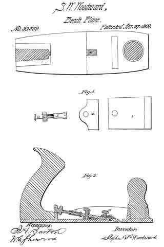
Figure 1 is a dissected view of the plane, and
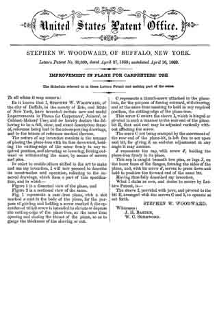
Figure 2 is a sectional view of the same.
Fig. 1 represents a cast-iron plane, with a slot marked a cast in the body of the plane, for the purpose of guiding and holding a screw marked b, the operation of which screw is intended to elevate or depress the cutting-edge of the plane-iron, at the same time opening and closing the throat of the plane, so as to gauge the thickness of the shaving or cut.
C represents a thumb-screw attached to the plane-iron, for the purpose of forcing outward, withdrawing, and at the same time assisting to hold in any required position, the cutting-edge of the plane-iron.
This screw C enters the sleeve I, which is hinged or pivoted in such a manner to the rear end of the plane-bit E, that said end may be adjusted vertically without affecting the screw.
The screw C not being cramped by the movement of the rear end of the plane-bit, is left free to act upon said bit, for giving it an endwise adjustment at any angle it may assume.
d represents the cap, with screw d, holding the plane-iron firmly in its place.
This cap is caught beneath two pins, or lugs J, on the inner faces of the flanges, forming the sides of the plane, and with its screw d, serves to press down and hold in position the forward end of the same bit.
Having thus fully described my invention,
What I claim as new, and desire to secure by Letters Patent, is —
The sleeve I, provided with jaws, and pivoted to the bit E, arranged with the screws C and b, to operate as set forth.
STEPHEN W. WOODWARD.
Witnesses:
J. H. BARTON,
W. C. SHERWOOD.