
| PLEASE NOTE: The images presented on this page are of low resolution and, as a result, will not print out very well. If you wish to have higher resolution files then you may purchase them for only $2.95 per patent by using the "Buy Now" button below. All purchases are via PayPal. These files have all been cleaned up and digitally enhanced and are therefore suitable for printing, publication or framing. Each zip package contains all the images below (some packages may contain more), and purchased files can be downloaded immediately. |
UNITED STATES PATENT OFFICE.
JAMES A. SEVEY, OF BOSTON, MASSACHUSETTS.
Letters Patent No. 98,305, dated December 28, 1869.
_________________
IMPROVEMENT IN PLANE FOR SHAVING WHALEBONE.
_________________
The Schedule referred to in these Letters Patent and making part of the same.
_________________
To all persons to whom these presents may come:
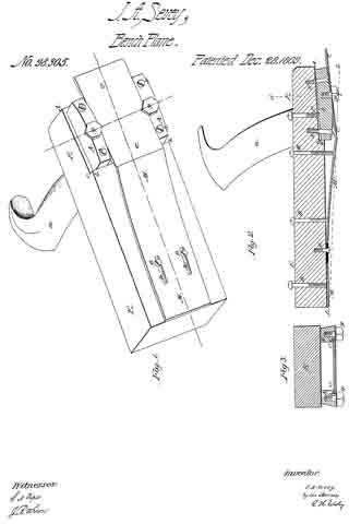
Be it known that I, JAMES A. SEVEY, of Boston, in the county of Suffolk, and State of Massachusetts, have invented a new and useful or Improved Machine or Implement for Stripping or Shaving Whalebone ; and I do hereby declare the same to be fully described in the following specification, and represented in the accompanying drawings, of which —
Figure 1 denotes a perspective view of it :
Figure 2, a verticle and longitudinal section ; and
Figure 3, a transverse section of it.
In such drawings —
E denotes a plane-stock, made of wood, or other proper material, and provided with a handle, a, which extends from it in manner as exibited in figs. 1 and 2.
At or near its heel, the said stock is rebated entirely across it, as shown at b c d, in fig. 2, and also in fig. 1.
Within the recess or rebate, I arrange, at suitable distances apart, and parallel to each other, two metallic blocks or plane-iron supporters A A, they being rebated on their inner edges, as shown at e e, in fig. 3, in order to receive and support a plane-iron or cutter, C, the bevel f of whose cutting-edge, is arranged upward, or in a manner as shown in fig. 2.
The plane-iron C is held to these supporters A A by means of clamp-screws g g, screwed into the supporters, and arranged, with reference to the plane-iron, in manner as represented.
Each supporter is held in place by three screws, S S P, two of which go through the supporter and screw into the plane-stock. The third screw, P, is arranged between the screws S S, and is screwed through the plane-stock, and against the supporter, the whole being as shown in fig. 2.
By means of these adjusting-screws S S P, the inclination or bevel of the knife or plane-iron can be so adjusted as to bring the cutting-edge thereof down to a plane, L L, which extends from the lower edge of the front end of a plate-spring, M, to the lower edges of the four screws g g.
In advance of the plane-iron C there is a spring-plate or throat-piece M, which is secured to the plane-stock E by means of two screws, B B, which go through slots h h, (made in the plate M,) and screw into the stock.
Furthermore, certain adjusting-screws, D D D, screw down through the stock E, and against the upper surface of the plate M. These screws, with the screws BB, and the slots h h, are to adjust the elastic throat-piece M, or enable it to be perfectly adjusted with reference to the cutting-edge of the plane-iron C.
The implement is to be used in the manner of a common carpenter’s plane, the spring-plate M being first properly adjusted, with reference to the cutting-edge of the plane-iron, so as to cause such edge, when forced against the end of a slab of whalebone, to strike it at the requisite depth.
As soon as the plane-iron enters the slab, the incline f will raise the shaving or part to be split, or force it up from the part below it, so as to split it therefrom.
The spring-plate or throat-piece, operating in conjunction with the knife-edge of the plane f, will not only yield, so as to allow the plane-iron to hit the end of the lab at the proper depth, but will afterward press upon the upper surface of the portion to be removed, and hold the whole down to the bench.
The implement, on being moved forward, will separate a strip of even thickness from the slab, however irregular the slab may be on its upper surface.
I am aware of the plane described in the United States patent, No. 50,947, dated November 14, 1865, and granted to Harrison Ogborn, and I make no claim thereto. My plane differs from it, in having its cutter C sustained by two adjustable supporters A A, which answer not only as means of holding the cutter, but as guides for the shaving, to direct it properly through and out the plane.
My plane also has the elastic throat-piece M. provided with adjustments, by which it can be adjusted both laterally and longitudinally, with respect to the edge of the plane-iron C ; whereas, the throat-piece of Ogborn’s plane is inelastic, and adjustable only laterally, or up and down.
The elastic or spring throat-piece M does not project over the plane-iron, but is arranged in front of it, and with its working end in the same plane with the cutting-edge of the knife C.
In order for the knife C to cut, the throat-piece M must first spring upward, and, while the shaving is being cut, the throat-piece is borne down on it by the inherent elastic force of the throat-piece, the same enabling very thin, and smooth, and even shavings to be removed from the whalebone. Consequently,
What I claim as my invention is as follows :
The combination and arrangement of the spring or elastic throat-piece M, (provided with adjusting-devices, as described,) with the plane-stock E, and the cutter or plane-iron C.
Also, the combination and arrangement of the plane-iron supporters A A, and the clamp-screws g, and adjusting-screws S S P, with the plane-stock E, the cutter C, and the mouth-piece M, provided with devices for adjusting it, as set forth.
J. A. SEVEY.
Witnesses:
R. H. EDDY,
F. P. HALE, Jr.