
| PLEASE NOTE: The images presented on this page are of low resolution and, as a result, will not print out very well. If you wish to have higher resolution files then you may purchase them for only $2.95 per patent by using the "Buy Now" button below. All purchases are via PayPal. These files have all been cleaned up and digitally enhanced and are therefore suitable for printing, publication or framing. Each zip package contains all the images below (some packages may contain more), and purchased files can be downloaded immediately. |
United States Patent Office.
CARL KUPFER, OF MADISON, WISCONSIN, ASSIGNOR TO HIMSELF AND KUND
J. FLEISCHER, OF SAME PLACE.
Letters Patent No. 81,795, dated September 1, 1868.
IMPROVEMENT IN PLANES FOR CUTTING BLIND-SLATS.
_________________
Specification of Letters Patent No. 81,795 dated July 4, 1854.
_________________
The Schedule referred to in these Letters Patent and making part of the same.
_________________
TO ALL WHOM IT MAY CONCERN:
Be it known that I, CARL KUPFER, of Madison in the county of Dane, and State of Wisconsin, have made new and useful Improvements in Slat-Cutting Machinery ; and I do hereby declare the following to be a full, clear, and exact description of the nature, construction, and operation of the same, sufficient to enable one skilled in the art to which it appertains to construct and use the same, reference being had to the accompanying drawings, which are made part of this specification, and in which —
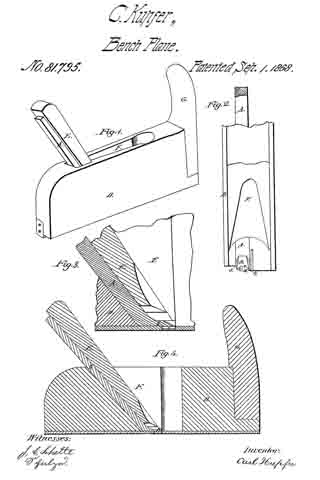
Figure 1 is a perspective view.
Figure 2 is an end sectional view.
Figure 3 is an enlarged side sectional view.
Figure 4 is a side sectional view.
The invention consists in the construction of a knife or plane bit, whose edge or edges are so shaped, arranged, and combined as to cut the top, sides and bottom of the slat at one stroke of the plane across the stick of timber from which the slat is to be cut, and in leaving a straight edge or side, against which the shoulder of the plane is brought, and which serves as a guide for the plane in cutting each succeeding slat.
The bit A is made of a piece of steel, of suitable dimensions for the size of the slat to be cut, with its lower cutting-end, B, bent to an angle of forty-five degrees, or thereabouts, from the line of the body of the bit, and projecting downwards, as shown at B, fig 4. This projection is pierced with a hole, as at C, fig. 2, of any desired shape for the slat, and in line with the face of the plane D, as shown at C, fig. 2; the upper and lower edges of the aperture being brought to sharp cutting-edges, as at 1 2, fig. 2.
In sharpening these edges, care must be taken to leave two lips, whose edges, 3 4, fig. 2, are at right angles with the upper and lower cutting-edges 1 2. The bit A is set in a plane-stock, D, and secured in the ordinary manner with a wedge, E, there being sufficient throat, F, for the escape of all shavings. The front end of the plane-stock is provided with a handle, G, to facilitate holding the tool firmly.
By the use of this tool I am enabled to avoid the use of sawed lumber of any kind, and, instead, use timber as it is split from the log, like fire-wood, or without splitting at all, and thus I save from one-half to nine-tenths of the timber, and consequently a large proportion of the cash outlay formerly paid for stock.
Having described my invention, what I claim, and desire to secure by Letters Patent, is —
1. The bit A, when constructed with sharpened upper and lower edges, 1 and 2, leaving two lips, 3 and 4, said lips to be at right angles with the upper and lower cutting-edges, substantially as and for the purpose set forth.
2. The combination of the bit A, as described and claimed, with the plane-stock, for the use and purposes specified.
CARL KUPFER.
Witnesses:
J. C. SCHELTE,
A. JURGENS.