No. 1,393,991 – Plane (John M. Dodenhof) (1921)
[paiddownloads id=”729″]1393991


UNITED STATES PATENT OFFICE.

_________________

JOHN H. DODENHOF, OF ST. LOUIS, MISSOURI.

PLANE.

_________________

1,393,991. Specification of Letters Patent. Patented Oct. 18, 1921.
Application filed September 24, 1920. Serial No. 412,431.

_________________

To all whom it may concern:

Be it known that I, JOHN M. DODENHOF a citizen of the United States, residing at St. Louis, in the county of St. Louis and State of Missouri, have invented certain new and useful Improvements in Planes, of which the following is a specification.

This invention relates to planes for dove-tailing tongue and grooving, dado work and the like, and the primary object of the invention is to provide an improved attachment for planes of this character, which is so constructed that dove tail tongue and grooving can be cut at any angle in an expeditious and simple manner.

Another object of the present invention is to provide an improved guide for dove tail tongue and grooving work and the like, which will hold the plane and its cutting blade at the correct and desired angle, the guide being so arranged and associated with the main stock of the plane in such a manner as to permit the same to be swung at any angle and at any distance from the main stock.

A still further object of the invention is to provide an improved sliding section for the main stock of the plane, so as to permit various sizes and shapes of cutting blades to be used with the plane, the sliding section being formed in separate pieces which are adjustable toward and away from the work, and toward the main stock.

A still further object of the invention is to provide an improved attachment for planes of the above character, which will be durable and efficient in use, one that will be simple and easy to manufacture, and one which can be placed upon the market and associated witii planes at a reasonable cost.

With these and other objects in view, the invention consists in the novel construction, arrangement and formation of parts as will be hereinafter more specifically described, claimed and illustrated in the accompanying drawings, forming a part of this specification, in which drawings:

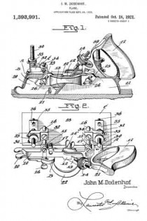
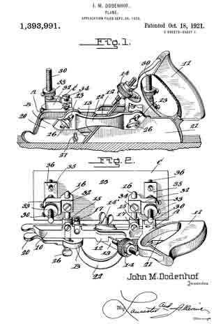
Figure 1 is a side elevation of the improved plane showing the same in use, the work being shown in longitudinal section.

Fig. 2 is a top plan view of the plane and its attachment.

Fig. 3 is a front elevation of the plane and its attachment showing the use of the same for making dove tail grooves, the work being shown in transverse section.

Fig. 4 is a fragmentary side elevation of the plane and attachment looking in the opposite direction from Fig. 1, illustrating the position of the plane and attachment when in use, the work being shown in section, and

Fig. 5 is a detail transverse section taken through the main stock and sliding section illustrating the means of adjustably connecting the sliding section with the main stock.

Referring to the drawings in detail, wherein similar reference characters designate corresponding parts throughout the several views, the letter A indicates the plane, B, its sliding section, and C, the improved adjustable guide therefor.

The plane A may be of the usual or any preferred form and of any desired make, or of the type utilized for making dove tails, tongue and grooving, dado work and the like. As shown the plane A includes the main stock 10 having the handle 11 arranged on one end of the same. The main stock 10 is provided with the usual cutting blade or tool guide 12 for the tool or blade 13. As shown the guide is arranged at an angle to the vertical in the usual manner and is provided with the usual holding blade nut and bolt 14’. As shown the bolt extends transversely of the stock. The handle 11 supports at its forward end the usual adjusting device 14, which may be of any preferred construction. The main stock 10 is provided with the straight laterally extending hollow bosses 15, which slidably support the guide arms 16, which are held in their preferred adjusted positions by means of set screws or the like 17. These arms 16 may be of any preferred length and are utilized for supporting the sliding section B and the improved attachment C.

The improved sliding section B of the plane is constructed similar to the usual sliding sections for planes of this character, with the exception that the same is constructed in three sections, namely, the forward body section 20, the rear body section 21 and the connecting bridge piece 22. The body sections 20 and 21 are formed of any preferred material and are in direct vertical alinement with each other and are adapted to receive between the same the cutting blades or tools which are carried by the main stock 10. The forward edge of the body piece 21 of the sliding section B is inclined to conform to the inclination of the guide 12 for the cutting tool or blade.

The bridge piece 22 may be connected to the body sections 20 and 21 in any preferred manner, and if so desired the terminals thereof may be welded or brazed to the body section. As shown the bridge piece 22 is substantially arcuate shaped in plan and is so shaped as to permit blades or cutting tools of various widths to be used. The body pieces 20 and 21 are provided with inclined guide slots 23, which slidably receive the flattened or polygonal shaped terminals 25 of the guide arms 16. It can be seen that the slidin section B may be raised or lowered according to the depth of the groove, tongue or the like being made. To hold the sliding section B in its adjusted position, the flattened or polygonal shaped terminals 25 of the guide arms 16 are provided with threaded bores for the set screws 26 which are adapted to frictionally engage the outer surface of the sliding section B. If so desired the sliding section B may be provided with the swinging spur 27 for cross grain work.

The improved attachment or side section C includes the flat rectangular shaped plate or bottom 28, which is adapted to engage the work and hold the main stock 10 with its cutting blade or tool at the desired angle for making the desired dove tail groove or tongue. The upper surface of the base plate or bottom 28 is provided adjacent to its opposite ends with the upstanding ears 29 which are connected to the lower terminals of the adjusting screw threaded stems 30 by means of pivot ins or the like 31. These screw threaded adjusting stems 30 are slidably carried by blocks 32 which are provided with transverse bores for the reception of the guide arms 16. It can be seen by referring to Fig. 2 of the drawings that the blocks 32 project laterally from the guide arms 16 and are adjustably mounted thereon toward or away from the main stock 10. These blocks are held in their adjusted positions on the guide arms by means of set screws or the like 34. It is to be also noted that not only are the guide arms themselves adjustable but that the blocks 32 are adjustably mounted thereon.

The screw threaded guide stems 30 are, as stated, slidably carried by the blocks 32 and these stems are held in their adjusted positions by means of upper and lower lock nuts 33 which are threaded on the stems into engagement with the opposite sides of the blocks. The lower terminals of the stems 30 are provided with the outwardly extending rigid plates 35, which adjustably support the screw threaded members 36, which are adapted to engage the upper surface of the guide plate or bottom 28 for holding the same at the desired angle in relation to the main stock 10 of the plane A. These screws 36 are held in their adjusted position by means of nuts 37 which are threaded thereon into engagement with the plates 35.

In operation of the plane and guide, the desired tool or cutting blade is placed in the guide 12 in the usual manner and the blade or tool is adjusted by means of the device 14. The sliding section B is then adjusted toward the blade by means of the sliding arms 16 until the section is at the desired point. The guide plate or bottom 28 is then slid on the guide arms 16 to the desired point and held in place by means of the set screws 34 provided for that purpose, after which the plate or bottom 28 is swung to the desired angle at which the dove tail grooves or tongues are to be made on the pivot pins 31, after which the set screws 36 are adjusted so as to hold the plates or bottoms in this position. The plate or bottom engaging the work will effectively hold the main stock 10 and its cutting blade at the desired angle and the dove tail will be made with the desired inclination to the walls thereof. The depth of the groove to be made can be determined by the distance on the plate 28 from the tool and this distance can be varied as desired by means of the threaded stem 30. If so desired, the position of the plate 28 can be changed from one side to the other to suit varying conditions.

The plane, if so desired, can also be used with the usual sliding section and fence (not shown) for rabbeting or the like, but the same forms no part of this invention.

Changes in details may be made without departing from the spirit or scope of this invention; but, I claim:

1. In a plane, the combination with a main stock, a sliding section adjustably carried by the main stock and arranged in parallel relation to the main stock, a cutting blade arranged between the sliding section and the main stock, of a guide including a laterally projecting pivoted plate arranged to turn both in a plane at right angles to the stock and in a plane parallel to the stock and sliding section, and means for varying the angle of the plate in relation to the main stock, sliding section and blade.

2. In a plane, the combination with a main stock, a sliding section adjustably carried by the main stock and arranged in spaced parallel relation thereto, a cutting blade arranged between the main stock and sliding section, of a guide including a laterally projecting plate adjustably toward and away from the main stock, means pivotally securing the plate in position to permit the same to turn both in a lane at right angles to the stock and sliding section and in a plane parallel to the stock and section, means for raising and lowering the plate in relation to the stock, and means for varying the angle of the plate in relation to the stock.

3. In a plane, the combination with a main stock, a sliding section adjustably carried by the main stock, a cutting blade arranged between the main stock and sliding section, of a guide including a laterally projecting substantially rectangular shaped plate, means pivotally securing the plate in position to permit the same to turn both in a plane parallel to the stock and sliding section and in a plane at an angle to the stock and sliding section, means for adjusting the height of the plate in relation to the main stock, sliding section and blade, and means for varying the angle of the plate in relation to the stock.

4. In a plane, the combination with a main stock, a pair of sliding guide arms carried by the stock, means for holding the guide arms in adjusted position, a sliding section adjustably carried by the guide arm, means for holding the sliding section in adjusted position, a cutting blade arranged intermediate the sliding section and main stock, of a guide including a pair of blocks adjustably mounted on the guide arm, threaded stems slidably carried by the blocks, means for holding the threaded stems in adjusted position in relation to the blocks, a substantially rectangular shaped flat plate pivotally carried by the lower ends of the stems, and means for holding the plate in adjusted position in relation to the stems.

5. As a new article of manufacture, a guide for bench planes comprising a flat plate, a pair of pivoted stems carried by the upper surface of the plate, blocks adjustably carried by the stems, means for holding the stems and the blocks in adjusted relation to each other, laterally projecting plates rigidly carried by the stems adjacent to their lower ends, adjustable set screws carried by the laterally projecting plates arranged to engage the upper surface of the first mentioned plate, the blocks having transversely extending bores therein, and set screws carried by the blocks arranged to extend into said bores.

JOHN M. DODENHOF.

No. 1,181,004 – Bench Plane (George W. Harvey) (1916)

[paiddownloads id=”711″]1181004


UNITED STATES PATENT OFFICE.

_________________

GEORGE W. HARVEY, OF JASPER, MISSOURI.

BENCH-PLANE.

_________________

1,181,004. Specification of Letters Patent. Patented Apr. 25, 1916.
Application filed July 22, 1915. Serial No. 41,306.

_________________

To all whom it may concern:

Be it known that I, GEORGE W. HARVEY, citizen of the United States, resident of Jasper, in the county of Jasper and State of Missouri, have made a certain new and useful Invention in Bench-Planes; and I declare the following to be a full, clear, and exact description of the same, such as will enable others skilled in the art to which it appertains to make and use the invention, reference being had to the accompanying drawings, and to letters or figures of reference marked thereon, which form a part of this specification.

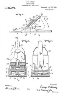
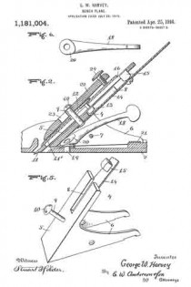
Figure 1 is a side view of the invention. Fig. 2 is a section on the line 2–2, Fig. 3. Fig. 3 is a section on the line 3–3, Fig. 1. Fig. 4 is a section on the line 4–4, Fig. 1. Fig. 5 is a detail perspective view of the bit iron holder. Fig. 6 is a detail top plan view of the adjusting lever.

The invention has relation to bench or carpenters’ planes, and it consists in the novel construction and combination of parts, as hereinafter set forth.

In the accompanying drawings, illustrating the invention, the numeral 2 designates the stock, having side flanges 3, 3, and 4 is the bit iron holder, having an incline 5 and lower side flanges 6, 6, pivoted to the flanges of the stock by a strong cross-pin 7. The bit holder has in its incline a slot 8, open at its upper end, and is provided with a stud 9, projecting upwardly at right-angles to the incline and having a head 10 at its upper end.

Resting upon the bit iron holder incline is the bit iron 11, a cap iron 11′ having therein a slot 12, of keyhole form, adapted to engage the head of the stud, when the bit and cap irons will slide downwardly to position, the contracted portion of the slot engaging the shank of the stud. Projecting from the lower wall of the bit iron, intermediately of its length, is a stud 13, fitting within the slot of the incline. An upwardly projecting, inclined spring arm 14 is secured at its lower end to the lower wall of the incline, and carries intermediately of its length an upwardly projecting squared stud 15, engaging a squared slot or seat 16 of the bit iron.

A wedge 22 has, intermediately of its length, a keyhole slot 23 therein, engaging over the headed end of the stud 9, said wedge having at its upper end a screw 24, having contact with the upper portion of the cap iron, to press said iron, with the bit iron, downwardly against the incline of the bit iron holder and bind it securely in place thereupon.

Located below the spring arm, about midway between the same and the floor of the stock, is a rearwardly projecting inclined lever 18, having at its lower end a pivot upon a vertical pin 19 of the stock, said lever having at its lower end an upper cam surface 20, against which the lower wall of the incline bears, so that when the lever is moved to one side or the other, the cam will engage the bit iron holder and move the same upwardly or allow the same to move downwardly, upon the cross~pin as a pivot, the bit iron holder and bit iron carried thereby rocking upon said cross-pin, to adjust the cutting edge upwardly or downwardly and thereby vary the thickness of the shaving, said lever being easily worked by one finger, without changing the grip upon the handle, so that delicate adjustments, to vary the thickness of the shaving, may be conveniently made. As the bit iron holder and bit iron are adjusted as stated, to vary the thickness of the shaving, a transverse spring 21, located beneath the rear portions of the flanges 6 of the bit iron holder, is put under tension, this transverse spring acting to press the bit iron holder in contact with the cam, and accomplishing the downward recking movement of the bit.

What I claim is:

1. In a plane, a stock, a bit iron holder pivoted to said stock, a bit iron upon said holder, a pressure spring for said holder and said bit iron in rear of said pivot, and a transversely movable adjusting lever having a vertical fulcrum pin connection with said stock and a cam end in contact with said holder forward of said pivot.

2. In a plane, a stock having side flanges, a bit iron holder having side flanges, a bit iron upon said holder, a pivotal cross-pin connecting the flanges of said stock and said holder, a pressure spring for said holder and said bit iron in rear of said cross-pin, and transversely movable adjusting lever having a vertical fulcrum pin connection with said stock and a cam end in contact with said holder forwardly of said cross-pin.

3. In a plane, a stock, a bit iron holder pivoted to said stock, a bit iron upon said holder, a pressure spring for said bit iron and said holder in rear of the pivot thereof, In testimony whereof I affix my signature, and a transversely movable rearwardly projecting lever having at its lower end a vertical fulcrum pin connection with the stock and an upper cam surface bearing against the said holder forwardly of the pivot thereof.

GEORGE W. HARVEY.

Witnesses:
LEIGH I. DODWELL,
ADOLPH McGEE.

_________________

Copies of this patent may be obtained for five cents each, by addressing the “Commissioner of Patents, Washington, D. C.”
_________________

No. 508,386 – Plane (Oliver R. Hayworth) (1893)

[paiddownloads id=”495″]508386


UNITED STATES PATENT OFFICE.

_________________

OLIVER R. HAYWORTH, OF TARKIO, MISSOURI, ASSIGNOR
OF ONE-HALF TO AMON A. CURFMAN, OF SAME PLACE.

PLANE.

_________________

SPECIFICATION forming part of Letters Patent No. 508,386, dated November 7, 1893.
Application filed May 18, 1893. Serial No. 474,692. (No model.)

_________________

To all whom it may concern:

Be it known that I OLIVER R. HAYWORTH, a citizen of the United States of America, residing at Tarkio, in the county of Atchison and State of Missouri, have invented certain new and useful Improvements in Planes; and I do hereby declare the following to be a full, clear, and exact description of the invention, such as will enable others skilled in the art to which it appertains to make and use the same, reference being had to the accompanying drawings, and to the letters of reference marked thereon, which form a part of this specification.

This invention relates to improvements in bench-planes; and it consists in the particular construction and combination of the parts, as will be hereinafter fully set forth, and pointed out in the claims.

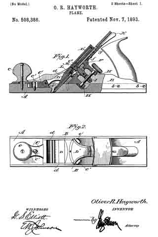
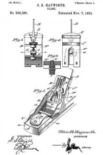
In the accompanying drawings, forming part of this specification, Figure 1 is a side view of the plane, partly in section. Fig. 2 is a plan view. Fig. 3 is a rear elevation of the part of the plane against which the bit rests. Fig. 4 is a front elevation of Fig. 3. Fig. 5 is a detail perspective view of the front portion of the plane with the cover of the pivoted holding cap removed; and Fig. 6 is a sectional view through the line x–x of Fig. 3.

A designates the base or bed-piece of the plane, which is preferably made of wood, the side edges thereof being cut away, as shown at a, to receive the metallic side pieces B which are secured to said base by the screws or bolts b. The base is slotted in the usual manner for the passage of the bit, and it is also recessed in its upper surface to receive the frames which adjust and hold the bit.

C designates a knob-plate, which is apertured near its forward end for the passage of the screw which secures the front knob c to the base. In rear of the aperture for the knob the plate is slotted for the passage of a set-screw or bolt c’, and to the rear end of the knob-plate is pivoted the holding cap D the rear face of which is adapted to bear upon the cap-plate of the bit. The lower end of the pivoted holding cap is out away to allow a free passage of the shavings, and the inner sides of the connecting arms d d are beveled, as shown at d’, so that the shavings will be guided toward the center of the plane. The pivoted holding cap is made in two parts, one part constituting the main frame and the other a covering plate, D’, which covering plate retains in place spring-actuated arms E E which have at their lower ends projecting catches which engage with notches or recesses in the side pieces B B of the plane so as to retain the pivoted holding cap in proper position. Above the catches e e the arms are provided with projections e’, which extend through the side pieces of the pivoted holding cap and provide means for retracting the catches, said catches being normally projected by means of a flat spring e2 which is positioned as shown in Fig. 5. The upper ends of the arms are rounded as shown to provide bearing surfaces or pivots.

It will be seen that by the construction hereinbefore described the knob-plate can be adjusted longitudinally upon the base of the plane to take up the wear of the parts and also to permit the use of bits and cap-plates of different thicknesses.

To the metallic side pieces and the base is rigidly secured the seat or frog provided for the bit, indicated by the letter F. This seat or frog is out away centrally for the passage of the adjusting lever G, said lever being pivoted between lugs which project from the rear side of the seat or frog, and above and below the lever project lugs H H in which is seated an adjusting screw having a head of ordinary construction. The central portion of the adjusting screw is threaded and engages with a threaded aperture in a block I pivoted within the rear end of the adjusting lever, said rear end being bifurcated to receive the block. By this construction I am enabled to provide rigid bearings for the adjusting screw and position the same so that it will be on a line with the front bearing surface of the frog F. The block I is slotted for the passage of the pivot-pin.

The frog is provided with a transverse recess in which is secured a flat spring f the free ends of which bear upon the rear surface of the bit, and above this spring the frog is provided with another transverse recess for the reception of a plate g having outturned ends which engage with the sides of the plane-bit, the rear side of the frog being recessed to receive a lever K which is pivotally attached to the plate g and to a stud or projection on the frog, the recess for the lever opening into the recess in which the plate slides.

The lower end of the lever K is bifurcated to embrace the stud or projection. The bit and cap-plate therefor are of substantially ordinary construction and are connected to each other by the screw L, and above the screw the cap-plate has a recessed lug, M, with which the forward end of the adjusting-lever G engages.

It will be observed that by simply turning the thumb-screw H the bit and its cap-plate may be adjusted vertically, and that the bit can be adjusted so that its cutting edge will be on a line with the under side of the plane by the use of the lever K.

When it is desired to remove the bit from the plane-stock it can be readily accomplished by simply pressing upon the projections e’ e’ of the arms E E, which will retract the catches and permit the holding cap to be swung upon its pivot.

I am aware that prior to my invention it has been proposed to provide a bench-plane with means for vertically and laterally adjusting the bit, and I do not therefore claim such construction broadly; but

What I do claim as new, and desire to secure by Letters Patent, is —

1. A bench plane comprising a wooden base having longitudinal side recesses, a transverse aperture of less width than the base through which the bit passes and recesses in front and rear of said transverse aperture, metallic side pieces secured to the base so as to lie partially in the longitudinal side recesses thereof, a knob-plate secured to the base so as to be located partially in the recess in front of the transverse aperture, a seat or frog attached to the base and metallic side pieces, the lower portion thereof lyin gin the recess in rear of the transverse aperture, and a holding cap pivoted to the rear end of the knob-plate, the parts being organized and combined substantially as shown, and for the purpose set forth.

2. In a plane, the combination, of a frog rigidly attached to the base and side pieces thereof, a cap-plate pivoted to the base of the frame and connected thereto so as to be adjustable longitudinally thereon, said cap-plate having catches which engage with recesses in the side pieces of the frame, for the purpose set forth.

3. In combination with a plane, the side pieces thereof having recesses on their inner sides, a holding cap which is pivotally secured to the base of the plane, said cap carrying spring-actuated catches which are adapted to engage with the recesses in the side pieces, for the purpose set forth.

4. In combination with a plane, a movable plate having pivoted thereto a cap-piece, said cap-piece having forwardly projecting portions the sides of which are cut away above the opening through which the bit passes, and catches for holding the cap-piece in engagement with the side pieces of the plane, substantially as shown.

5. In combination with a plane, an adjustable plate C, a holding cap having forwardly and downwardly extending portions pivotally attached to the adjustable plate, catches carried by the holding plate and adapted to engage with recesses in the sides of the plane, substantially as shown, and for the purpose set forth.

6. In a plane, the combination, of the pivoted holding cap the upper portion of which is recessed for the reception of arms having at their lower ends outwardly projecting catches and intermediate projections e’ e’ to provide for retracting the catches, together with a spring for projecting the arms, substantially as shown, and for the purpose set forth.

In testimony whereof I affix my signature in presence of two witnesses.

OLIVER R. HAYWORTH.

Witnesses:
A. L. GRAY,
C. R. BARROW.

No. 405,540 – Plane (John J. Driver) (1889)

[paiddownloads id=”450″]405540


UNITED STATES PATENT OFFICE.

_________________

JOHN J. DRIVER, OF ST. LOUIS, MISSOURI.

PLANE.

_________________

SPECIFICATION forming part of Letters Patent No. 405,540, dated June 18, 18589.
Application filed December 5, 1888. Serial No. 292,703. (No model.)

_________________

To all whom it may concern:

Be it known that I, JOHN J. DRIVER, a citizen of the United States, residing at St. Louis, in the State of Missouri, have invented certain new and useful Improvements in Planes, of which the following is such a full, clear, and exact description as will enable any one skilled in the art to which it appertains to make and use the same, reference being had to the accompanying drawings, forming part of this specification.

My invention relates to handles for planes, whereby the same can be manipulated by persons when standing to plane floors and the like, obviating the necessity of getting down on the knees.

The invention consists in features and details of construction which will new be set forth at length, and then particularly pointed out in the claims making a part hereof.

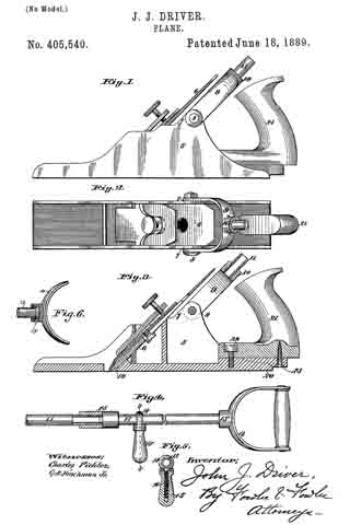
Figure 1 is a side elevation of a plane having my handle applied thereto. Fig. 2 is a plan view of the same. Fig. 3 is a longitudinal sectional view of the same. Fig. 4 is a view showing the handle only. Fig. 5 is a section on the line 5 5 of Fig. 4. Fig. 6 is a section of a detail.

The same figures of reference indicate the same parts throughout the various views.

5 is the plane, whichis of any ordinary construction and preferably made of metal.

6 is the cutter-blade, which is adjusted in said plane by any ordinary means. This means makes no part of my invention. I entend the metal sides of the plane to form ears 7 at each side of said plane, and to these ears 7, I journal my handle by a bolt 8, which passes through said handle and said ears.

The handle is preferably made of a bow-shaped piece 9, which has a screw-threaded socket 10 at its top and middle. This screw-threaded socket receives, preferably, a rod or pipe 11, screw-threaded at both ends, of any desired length, which may be joined to a second piece of pipe 12 to form the handle. The pipes or rods 11 and 12 are joined together by a nut 13, having a right and left hand screw-thread, so that when the nut is screwed down the ends of the rods 11 and 12 are brought together and make a tight joint. To the pipe 12 is swiveled at the point 13′ a handle 14, so that said handle 14 may be turned at any angle. Upon the pipe or rod 12 is also a second handle 15, which is made so as to be adjustable along said rod to accommodate the person using the plane. This handle 15 is made up of a screw-threaded bolt 16, which passes through the wooden part 15 of the handle, and has an eye 18 for receiving the rod 12. By screwing the wooden part 15 in one or the other direction it can be made to approach or recede from the rod 12, and thus allow said handle to be moved along said rod or fastened securely to the same at any point. The handle 14 is for one hand of the user and the handle 15 for the other hand. The ears 7 are about midway between the cutting-line 19 and the heel 20 of the plane, in order that the handle maybe attached to the plane at a point midway between 19 and 20, so as to equalize the pressure at the point 19 and the point 20.

If the handle were attached to the plane farther back, too much pressure would be thrown upon the heel 20 of the plane and too little pressure put upon the cutting-line 19. So, too, if the handle were attached farther forward of the plane too much pressure would be applied along the cutting-line.

The bolt 8 can be readily removed when it is desired to take the handle off of the plane and use it as an ordinary plane. Said handle can be made of any length by joining together any number of sections 11 and 12.

By the means described floors and other objects can be planed by persons when standing as readily as when upon the knees and with much less fatigue.

The invention is simple and effective, the construction strong and of small cost.

21 is the ordinary handle of the plane, which is fastened to said plane by screws 22 and 23, and may be removed from the plane, if in the way, when the other handle is attached.

Having fully set forth my invention, what I desire to claim and secure by Letters Patent of the United States as my invention is —

1. A handle for planes, consisting of the bow-shaped part 9, having screw-threaded socket 10, one or more screw-threaded rods joined to the same, a handle 14, swiveled to the upper end of said rods, and a handle 15, adjustably secured along said rods, for the purpose described.

2. The combination, with a plane, as herein set forth, of the ears 7, a bow-shaped piece 9, swiveled to said ears 7 by a bolt 8, screw-threaded socket 10 upon said bow-shaped piece, screw-threaded rod 11, adapted to be inserted in said socket 10, a second screw-threaded rod 12, a nut 13, having right and left hand screw-threads thereon for joining the rods 11 and 12 together, a handle 14, swiveled to said rod 12, and a handle 15, adjustable along said rod 12, substantially as and for the purpose described.

In testimony whereof I have hereunto set my hand and affixed iny seal, this 3d day of December, 1888, in the presence of the two subscribing witnesses.

JOHN J. DRIVER. [L. S.]

Witnesses:
A. C. FOWLER,
W. S. REEDER.

No. 221,763 – Improvement In Grooving-Irons (John W. Ammons) (1879)

[paiddownloads id=”306″]221763


UNITED STATES PATENT OFFICE.

_________________

JOHN W. AMMONS, OF COLUMBIA, MISSOURI, ASSIGNOR TO HIMSELF AND JOHN P. HORNER, OF SAME PLACE.

IMPROVEMENT IN GROOVING-IRONS.

_________________

Specification forming part of Letters Patent No. 221,763, dated November 18, 1879; application filed September 15, 1879.

_________________

To all whom it may concern:

Be it known that I, JOHN W. AMMONS, of Columbia, in the county of Boone and State of Missouri, have invented a new and Improved Grooving-Iron, of which the following is a specification.

My invention relates to improvements in the tongued irons or bits used in grooving-planes.

Heretofore the form of these irons has been such as to leave the corners of the groove sharp. This is objectionable on account of their liability to break off when the tongue is forced in and carried back into the groove, whence they have to be removed at a great expense of time and trouble; or if allowed to remain they interfere with the making of a good joint. To prevent this with the present tools, it is the habit of many workmen to chamfer off the corners with an ordinary rabbeting-plane; but this requires the use of another tool and the expenditure of valuable time.

The object of my invention is to provide a plane-iron which will chamfer off the outer corners of the groove simultaneously with the planing of the groove.

The invention consists in a plate with beveled cutting-edges, a slot, and a longitudinal groove, in combination with a grooving-iron provided with a cutting-edge, as hereinafter described.

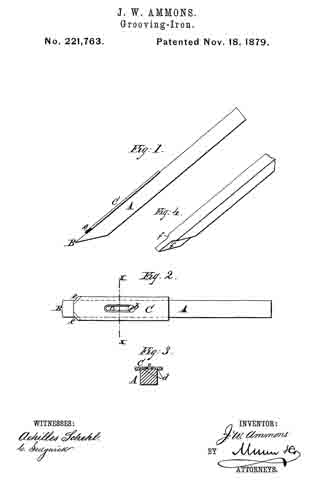
In the accompanying drawings, Figure 1 is a side elevation of my improved iron. Fig. 2 is a plan view of the same. Fig. 3 is a cross-section on line x x of Fig. 2; and Fig. 4 represents, in perspective, a modified construction of the iron.

Similar letters of reference indicate corresponding parts.

Referring to the drawings, A is the grooving bit or iron, made of a rectangular bar of steel, with cutting-edge B. On the upper side of iron A is placed a flat plate of steel, C, which is secured to the bit by a set-screw, b, passed down through the slot c in the plate into a threaded hole in the bit.

In the under side of the plate is a shallow longitudinal groove, d, sufliciently wide to receive the bit, as shown in Fig. 3. This groove d, together with the set-screw b, connects the plate C rigidly with the bit A, so that the plate C can neither rise nor lose its parallel adjustment with relation to the bit.

At the lower end of plate C the corners are chamfered or beveled off at any suitable angle, and the corners are given sharp cutting-edges e e.

The plate C is designed to extend one-sixteenth of an inch beyond the sides of the bit, so that the angular cutting-edges e e will come in contact with the sides of the groove cut by the bit. The object of this arrangement is to chamfer off the upper corners of the sides of the grooves at the same time the groove is planed, so as to enable the flooring-tongue to be entered into the groove without trouble, and without liability of breaking off the corners of the groove and forcing the splinters in the groove, as before mentioned.

The lower end of plate C forms the shoulders of the plane-iron to limit the depth of the groove.

In Fig. 4 is shown a bit with the shoulders forming a part thereof, in the usual manner. Herein the front lower edges, f f, are cut off at an angle and sharpened to an edge, the same as the edges e e of the plate C.

Both forms of plane-irons operate in the same way to chamfer off the corners of the sides of the groove; but the arrangement first described offers superior facilities for keeping the bit in good order, on account of the ease with which the edges e e can be sharpened.

Having thus fully described my invention, I claim as new and desire to secure by Letters Patent —

The plate C, having beveled cutting-edges e e at a suitable angle, and provided with a longitudinal groove, d, and slot c, and set-screw b, in combination with the grooving-iron having cutting-edge B, for the purpose of chamfering off the corners of the sides of the grooves, substantially as described.

JOHN W. AMMONS.

Witnesses:
F. D. EVANS,
I. O. HOCKADAY.

No. 99,275 – Improvement In Bench-Planes (Louis D. Tredway) (1870)

[paiddownloads id=”163″]99275


UNITED STATES PATENT OFFICE.

_________________

LOUIS D. TREDWAY, OF ST. LOUIS, MISSOURI.

IMPROVEMENT IN BENCH-PLANES.

_________________

Specification forming part of Letters Patent No. 99,275, dated January 25, 1870.

_________________

To all whom it may concern:

Be it known that I, LOUIS D. TREDWAY, of the city and county of St. Louis, and State of Missouri, have invented certain new and useful Improvements in Bench-Planes; and I do hereby declare that the following is a full, clear, and exact description of the same, reference being had to the accompanying drawings, which make a part of this specification, and in which —

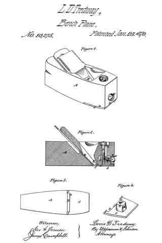
Figure 1 represents a view in perspective of a plane embracing my improvements. Fig. 2 represents a vertical longitudinal section thereof. Fig. 3 represents a bottom view of the plane. Fig. 4 represents a view in perspective of the metallic shoe detached from the plane.

My improvements consist in the employment of a front adjusting-screw, in connection with a double-socketed boss projecting from the metallic shoe, and a vertical clamping-screw, whereby the said metallic shoe is not only adjusted to regulate the fineness of the cut, but held by said adjusting-screw, so as to prevent its being forced back against the edge of the bit, which would be the case if such adjustment simply depended upon the vertical clamp-screw; in constructing the metallic shoe with projections on each side thereof contiguous to the bit, for the purpose of forming a brace and guide to the lower end of the bit and a support to the throat end of the plate, which, in connection with the adjusting-screw, allows the said metallic shoe to be adjusted and held always in a line parallel with a line drawn through the center of the plane; and in beveling that edge of the metallic shoe adjacent to the bit, so as to maintain an angle of about ninety degrees with reference to the bit, for the purpose of allowing the throat of the plane to clear itself more rapidly of shavings and effectually prevent choking.

In the accompanying drawings, A represents the stock of the plane, constructed and provided with a bit, B, in the usual manner.

The metallic shoe D is fitted in a recess, D, made on the under side of the front portion of the plane, and extends from the end thereof to the edge of the bit B. It is provided with a boss, E,which extends within a cavity made in the stock A, so as to allow it to be adjusted nearer to or farther from the bit, and fitted l I with a screw-socket, a, to receive a vertical screw, F, by which the shoe C is clamped when adjusted. It is also provided with a screw-socket, b, in its front side, into which a horizontal adjusting-screw, G, is inserted. The head c of this screw G is secured within a thimble, H, countersunk in the front end of the stock A, by means of the shoulders formed by the head c on one side and a pin, d, on the other side of the thimble, passing through the screw G, so as to lock it therewith. This screw not only serves to adjust the metallic shoe C, but serves to brace it against any movement toward the cutting-bit B. This is especially advantageous, because the vertical clamping-screw F is liable to become loose, and is not sufficient to clamp the metallic shoe against the thrust of the plane when brought into sudden contact with a knot or other hard resistance in the timber. Neither is it sufficient to resist the tendency of the shoe to be forced backward against the edge of the bit in “backing the plane.” The adjusting screw G therefore avoids injury to the bit at all times by preventing its contact with the shoe C, which would be the case if the clamp-screw only were used. The inner edge of this metallic shoe C is cut out or made with a recess, D, for the reception of the cutting-edge of the bit B in such a manner as to leave an arm or projection, I, at each end thereof, and the space between these arms is just equal to the width of the bit, for the double purpose of forming a guide and support to the cutting end of the bit and lateral supports to the inner end of the shoe, for it will be seen that when the bit is placed between the arms I of the shoe its lower portion can have no transverse movement whatever, but must present a straight edge to the bottom of the plane, as the arms of the shoe form stops thereto on either side. Neither can the inner end of the plate have any side movement, because the arms are locked with the bit. This result could not be obtained without these supporting-arms, because the sides of the throat are liable to constant wear.

The end of the recessed portion D of the shoe C is beveled inward, as represented at J, so as to present an angle to the face of the bit of ninety degrees, more or less, and as this bevel opens into the throat K of the plane, it effectually prevents clogging, which would not be the case if the end of the shoe were att right angles to its face.

The head of the vertical clamp-screw F is fitted within a thimble on the upper side of the stock A, which is provided with a slot, L, to allow the screw-bolt which passes through it into the boss E, to move with the adjustment of the metallic shoe, and this screw must be unclamped whenever it is necessary to turn the adjusting-screw, and when the shoe is adjusted it is again clamped.

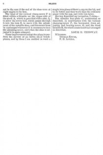
These improvements adapt the plane to perform the service of an entire set of bench-planes, and by them I am enabled to work a single-iron plane without a cap on the bit, and to do better and finer work than the ordinary plane with the cap, and with less labor.

Having described my invention, I claim —

The metallic face-plate C, constructed as described, in combination with the vertical clamping-screw F, the horizontal front adjusting and bracing screw, G, and the fixed thimble H, the whole constructed and arranged as described.

LOUIS D. TREDWAY.

Witnesses:
THOMAS KEYES,
F. D. LOVELL.

No. 82,074 – Improvement In Planes (Valentin Bitsch) (1868)

[paiddownloads id=”144″]82074


United States Patent Office.


VALENTIN BITSCH, OF ST. LOUIS, MISSOURI.

Letters Patent No. 82,074, dated September 15, 1868.

_________________

IMPROVEMENT IN PLANES.

_________________

The Schedule referred to on these Letters Patent and making part of the same.

_________________

TO ALL WHOM IT MAY CONCERN:

Be it known that I, VALENTIN BITSCH, of St. Louis, in the county of St. Louis, and State of Missouri, have made certain new and useful Improvements in Planes for working slats for Venetian window-blinds; and I do hereby declare that the following is a full and clear description thereof, reference being had to the accompanying drawings, and to the letters of reference marked thereon.

The object of this invention is to provide a plane suitable in every respect for cutting the thin, narrow strips used in the construction of Venetian window-blinds, from boards applicable to the purpose.

The plane is so constructed that both edges of the slats are bevelled off on both sides to a feather-edge, for the purpose of fitting the slats so as not to cut or rupture the cords that form the warp, when the blind is rolled up. Formerly, the edges of blind-slats for this kind of blinds were made square, and in rolling up and unrolling the blinds, the cords that formed the warp were abraded and soon ruptured across the square corners. It is to remedy these evils that the present form of plane is constructed.

To enable those skilled in the art to make and use my improved plane, I will proceed to describe its construction and operation.

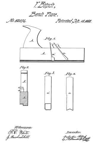
Figure 1 of the drawings is a side elevation of one of the improved planes.
Figure 2 is an end elevation of the same.
Figure 3 is an elevation of one of the plane-bits.
Figure 4 is an elevation of the other plane-bit.

The plane-stock A is provided with a handle, A’, in the usual manner, and its section is somewhat in the form of a rabbet-plane, as is shown in fig. 2. There are two plane-bits, a a’, fixed in the stock A, as is clearly shown in fig. 1. The plane a is somewhat in advance of the plane a’, and, as is shown in fig. 3, its cutting-edge is somewhat V-shaped, the salient point of the V forming a re-entering angle directed up into the body of the plane, thus leaving the lower outside corners projecting downward in such positions as to cut off and properly bevel the two top corners of the blind-slat as it passes through the plane. The plane-bit a’ is of a loop-shape, as is shown in fig. 4, and it is intended to cut under the slat and release it from the solid board from which it is cut. This bit may be set deep enough to cut the slat of the required thickness, and it will gauge it of a perfectly uniform thickness. The exterior corners of the cutting-edge of the bit a’ should be elevated, as is shown in fig. 4, for the purpose of bevelling off the two bottom corners of the blind-slat, for the purpose already described.

Having described my invention, what I claim, is —

The combination of the bit a, having its lower cutting-edges to form a re-entering angle, with the open-shank bit a’, having its lower cutting-edges arranged with bevelled corners, acting with the plane-stock A, to form blind-slats, whose narrow edges are chamfered, substantially as set forth.

VALENTIN BITSCH.

Witnesses:
GEO. P. HERTHEL, Jr.,
J. BESCHESTOBILL.