
| PLEASE NOTE: The images presented on this page are of low resolution and, as a result, will not print out very well. If you wish to have higher resolution files then you may purchase them for only $2.95 per patent by using the "Buy Now" button below. All purchases are via PayPal. These files have all been cleaned up and digitally enhanced and are therefore suitable for printing, publication or framing. Each zip package contains all the images below (some packages may contain more), and purchased files can be downloaded immediately. |
UNITED STATES PATENT OFFICE.
_________________
LOUIS D. TREDWAY, OF ST. LOUIS, MISSOURI.
IMPROVEMENT IN BENCH-PLANES.
_________________
Specification forming part of Letters Patent No. 99,275, dated January 25, 1870.
_________________
To all whom it may concern:
Be it known that I, LOUIS D. TREDWAY, of the city and county of St. Louis, and State of Missouri, have invented certain new and useful Improvements in Bench-Planes; and I do hereby declare that the following is a full, clear, and exact description of the same, reference being had to the accompanying drawings, which make a part of this specification, and in which —
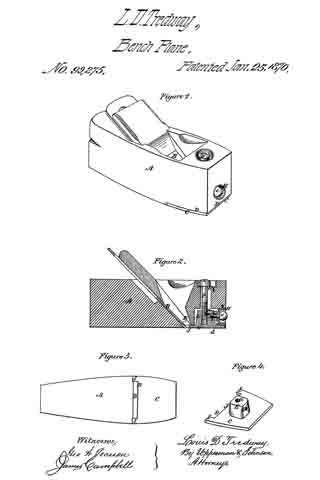
Figure 1 represents a view in perspective of a plane embracing my improvements. Fig. 2 represents a vertical longitudinal section thereof. Fig. 3 represents a bottom view of the plane. Fig. 4 represents a view in perspective of the metallic shoe detached from the plane.
My improvements consist in the employment of a front adjusting-screw, in connection with a double-socketed boss projecting from the metallic shoe, and a vertical clamping-screw, whereby the said metallic shoe is not only adjusted to regulate the fineness of the cut, but held by said adjusting-screw, so as to prevent its being forced back against the edge of the bit, which would be the case if such adjustment simply depended upon the vertical clamp-screw; in constructing the metallic shoe with projections on each side thereof contiguous to the bit, for the purpose of forming a brace and guide to the lower end of the bit and a support to the throat end of the plate, which, in connection with the adjusting-screw, allows the said metallic shoe to be adjusted and held always in a line parallel with a line drawn through the center of the plane; and in beveling that edge of the metallic shoe adjacent to the bit, so as to maintain an angle of about ninety degrees with reference to the bit, for the purpose of allowing the throat of the plane to clear itself more rapidly of shavings and effectually prevent choking.
In the accompanying drawings, A represents the stock of the plane, constructed and provided with a bit, B, in the usual manner.
The metallic shoe D is fitted in a recess, D, made on the under side of the front portion of the plane, and extends from the end thereof to the edge of the bit B. It is provided with a boss, E,which extends within a cavity made in the stock A, so as to allow it to be adjusted nearer to or farther from the bit, and fitted l I with a screw-socket, a, to receive a vertical screw, F, by which the shoe C is clamped when adjusted. It is also provided with a screw-socket, b, in its front side, into which a horizontal adjusting-screw, G, is inserted. The head c of this screw G is secured within a thimble, H, countersunk in the front end of the stock A, by means of the shoulders formed by the head c on one side and a pin, d, on the other side of the thimble, passing through the screw G, so as to lock it therewith. This screw not only serves to adjust the metallic shoe C, but serves to brace it against any movement toward the cutting-bit B. This is especially advantageous, because the vertical clamping-screw F is liable to become loose, and is not sufficient to clamp the metallic shoe against the thrust of the plane when brought into sudden contact with a knot or other hard resistance in the timber. Neither is it sufficient to resist the tendency of the shoe to be forced backward against the edge of the bit in “backing the plane.” The adjusting screw G therefore avoids injury to the bit at all times by preventing its contact with the shoe C, which would be the case if the clamp-screw only were used. The inner edge of this metallic shoe C is cut out or made with a recess, D, for the reception of the cutting-edge of the bit B in such a manner as to leave an arm or projection, I, at each end thereof, and the space between these arms is just equal to the width of the bit, for the double purpose of forming a guide and support to the cutting end of the bit and lateral supports to the inner end of the shoe, for it will be seen that when the bit is placed between the arms I of the shoe its lower portion can have no transverse movement whatever, but must present a straight edge to the bottom of the plane, as the arms of the shoe form stops thereto on either side. Neither can the inner end of the plate have any side movement, because the arms are locked with the bit. This result could not be obtained without these supporting-arms, because the sides of the throat are liable to constant wear.
The end of the recessed portion D of the shoe C is beveled inward, as represented at J, so as to present an angle to the face of the bit of ninety degrees, more or less, and as this bevel opens into the throat K of the plane, it effectually prevents clogging, which would not be the case if the end of the shoe were att right angles to its face.
The head of the vertical clamp-screw F is fitted within a thimble on the upper side of the stock A, which is provided with a slot, L, to allow the screw-bolt which passes through it into the boss E, to move with the adjustment of the metallic shoe, and this screw must be unclamped whenever it is necessary to turn the adjusting-screw, and when the shoe is adjusted it is again clamped.
These improvements adapt the plane to perform the service of an entire set of bench-planes, and by them I am enabled to work a single-iron plane without a cap on the bit, and to do better and finer work than the ordinary plane with the cap, and with less labor.
Having described my invention, I claim —
The metallic face-plate C, constructed as described, in combination with the vertical clamping-screw F, the horizontal front adjusting and bracing screw, G, and the fixed thimble H, the whole constructed and arranged as described.
LOUIS D. TREDWAY.
Witnesses:
THOMAS KEYES,
F. D. LOVELL.