
| PLEASE NOTE: The images presented on this page are of low resolution and, as a result, will not print out very well. If you wish to have higher resolution files then you may purchase them for only $2.95 per patent by using the "Buy Now" button below. All purchases are via PayPal. These files have all been cleaned up and digitally enhanced and are therefore suitable for printing, publication or framing. Each zip package contains all the images below (some packages may contain more), and purchased files can be downloaded immediately. |
United States Patent Office.
GEORGE CYRUS BECKWITH, OF BOSTON, MASSACHUSETTS.
Letters Patent No. 99,137, dated January 25, 1870.
_________________
IMPROVEMENT IN JOINERS’ PLANES.
_________________
The Schedule referred to in these Letters Patent and making part of the same.
_________________
To all whom it may concern:
Be it known that I, GEORGE CYRUS BECKWITH, of Boston, in the county of Suffolk, and State of Massachusetts, have made a new and useful Invention, having reference to Joiners’ Planes; and do hereby declare the same to be fully described in the following specification, and represented in the accompanying drawings, of which —
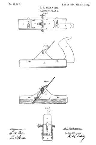
Figure 1 is a top view;
Figure 2, a side elevation;
Figure 3, an end view; and
Figure 4, a longitudinal section of a joiners’ plane, containing my invention.
This plane has a stock, capable of being expanded and contracted, for the purpose of adapting it to hold plane-irons or cutters, and throat-pieces, of different sizes or widths. lt also has a new and peculiar mechanism for holding the plane-iron or cutter in place in the stock and throat-piece.
The stock is mainly composed of two jaws A B, the handle C being affixed to one of them, viz, that marked A.
Screws a a go through holes made in the jaw B, and screw into projections b b, extended from the jaw A.
Furthermore, a duplex thumb-screw, D, goes through the upper parts of the middles of the two jaws, and over the plane-iron or cutter E, which, with a wooden base-plate or throat-piece, F, is arranged between the two jaws, in manner as represented.
The duplex thumb-screw has two screw-threads c d, which are pitched or run in opposite directions, relatively to one another, one being what is usually termed “a right-hand screw,” and the other “a left-hand screw.”
One of these screws is screwed into the jaw-plate A, and the other into the jaw-plate B, the whole being so that a person, by revolving the duplex screw in one direction, will cause the jaw-plates to recede from one another, and, by turning the said screw in the opposite direction, will cause the two plates or jaws to approach one another. The screws a a serve to compress the jaws upon a throat-piece, when placed between them.
For better supporting a throat-piece by the jaws, I usually make each of the latter with a tongue, f, projecting from its inner side, such tongue being to enter a corresponding groove, g, made in the next adjacent edge of the throat-piece. This throat-piece may have a flat bottom, or it may have a bottom formed like that of any common moulding-plane.
It is intended, by my invention, to have a series of throat-pieces of different widths, and also to have a series of plane-irons or cutters, and cap-irons, to correspond with such, the same being to enable a joiner with one stock, and such a series of throat-pieces and plane-irons, and cap-irons, to compose such a plane as his necessities may require front time to time, whether such be a plane for moulding, or for plane-surface work.
The throat-piece F has a chip-throat, h, made through it, such being to receive the plane-iron or cutter E, and the cap-iron H.
For the support of the plane-iron, the two jaw-plates are provided with rebated ledges, one of which is shown at i, in fig. 4.
Furthermore, a stud, k, extends from the inner face of each jaw-plate, in manner as shown in figs. 1 and 4. These studs serve as bearings or fulcra for the cap-plate, which is passed underneath both of them, and, at its lower part, rests on the plane-iron or cutter.
There is, between the two screws of the thumb-screw D, an arm, l, which turns freely on the shank of the screw, or is pivoted to the screw, so as to be capable of turning up and down thereon.
A cammed lever, L, jointed to the said arm, either bears upon the plane-iron, or upon a spring, n, projected from the rear part of the arm, and resting on the plane-iron.
By pressing down the tail or handle o of the cammed lever L, the arm I will be elevated against the cap-iron, and the cam p of the lever will be forced against the plane-iron, and thus, by means of the iron and the cammed lever, and the supports of the plane-iron and the cap-iron, such plane-iron and cap-iron may be fastened simultaneously in place in the stock and throat-piece.
In the above-described plane, I claim, as my invention, the following, viz:
The stock, as composed of the two jaws A B, and their clamping and expanding dowels or screws a a D, substantially as set forth, in combination with a separate throat-piece, F, as explained.
Also, the combination of the arm Z and the cammed lever L, applied to the duplex extension-screw D, and arranged with the plane-cutter E and the cap~iron H, as explained.
GEORGE CYRUS BECKWITH.
Witnesses :
R. H. EDDY,
S. N. PIPER.