
No. 779,392 – Plane (Otto Bjordal) (1905)


UNITED STATES PATENT OFFICE.
_________________
OTTO BJORDAL, OF CHICAGO, ILLINOIS.
PLANE.
_________________
SPECIFICATION forming part of Letters Patent No. 779,392, dated January 3, 1905.
Application filed April 2, 1904. Serial No. 201,362.
_________________
To all whom it may concern:
Be it known that I, OTTO BJORDAL, a citizen of the United States, residing at Chicago, in the county of Cook and State of Illinois, have invented a new and useful Plane, of which the following is a specification.
My invention relates to improvements in planes which are provided with an adjustable blade and a handle to manipulate the same; and the objects of my improvement are, first, to provide a cam under the lower end of the blade to adjust the same; second, to provide a set-screw to assist in adjusting the blade; third, to afford facilities for shifting the upper end of the blade to either side; fourth, to provide a cheap and simple construction of the cap cam-lever; fifth, to provide means whereby the plane-handle can be filted into any desired position, and other objects which will become apparent from the description to follow. I attain these objects by the construction shown in the accompanying drawing.
Heretofore planes of this class were provided with means for adjusting the blade which required the blade to slide longitudinally while being tightly clamped in position. This construction often made it impossible to make a fine adjustment. With my construction the adjustment of the blade is accomplished by slightly bending or springing the blade and without moving the blade longitudinally in its bearing. This is made possible by placing a cam-shaft under the lower end of the blade, which has a lever connected to one end, and by moving the said lever forward and back the cam-shaft is rocked in its bearing so as to lower and raise the cutting edge of the blade. To securely hold the blade against any longitudinal movement, I provide a set-screw in the bed or frame of the plane, which is brought to bear against the head of the screw, which locks the blade and fore guide together. This construction enables the user to adjust the cutting edge of the blade to a thousandth part of an inch, or even finer, if found necessary, without the slightest danger of the blade being forced out of the adjustment while the plane is in use, as often occurs with the present construction of planes.
When the cutting edge of the blade is not ground exactly or straight across, it requires that the upper end of the blade be shifted from side to side. I accomplish this side movement by providing a rotatable disk in the blade, the upper exposed side of the disk being provided with a lever or thumb-piece and the lower side of the disk being provided with an eccentric-pin which engages a slot in the bed or frame of the plane.
The cap cam-lever of my device is pivoted in the end of the cap by having two oppositely-extending lugs resting in sockets provided in the cap, and no rivet or pin is used, as is the casein the present construction of planes.
It is often desirable for convenience while working to have the inclination of the handle of the plane changed, depending on the height of the mechanic using the plane and the height of the work from the floor. I make provision for such adjustment by having a curved slotted plate on the body of the plane and a headed bolt on the handle to move in said slot and a means for clamping the bolt securely in any position in the slot.
Referring to the drawing, similar reference characters refer to similar parts.
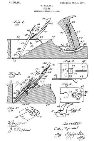
The body of the plane 10 is provided with the ordinary well or socket 11 for the reception of the blade 12 and its cooperating parts. While I have shown and will describe my invention in connection with a wooden plane it will be understood that the same can be applied to a metal plane.
The blade 12 is clamped tightly to the fore guide 18 in the ordinary manner by the screw 14. A bed-plate or frame 15 is rigidly secured to the oblique bottom of the well 11, and the blade 12 and fore guide 13 are tightly clamped to the same in the ordinary manner by the cap 16 and the cap-screw 17. The cap-lever 18 is pivotally attached to the cap by having its integral lugs 19 set into the sockets 20, provided in the cap 16, the cap 16 being slotted between the sockets 20 to permit the free passage of the lever 18. I provide a leaf-spring 21, riveted to the lower side of the cap, whose free end rests against the under side of the lever 18 and retains the lugs 19 in their cooperating sockets. The leaf-spring 21 also serves as a bearing-surface when the lever is operated. A depression or socket 22 is provided in the upper surface of the bed-plate 15 for the reception of the head of the screw 14, the depression 22 being somewhat larger than the head of the screw 14. A set-screw 23 is secured in the bed-plate 15, so arranged that it can be screwed against the head of the screw 14, and thus force the blade 12 down to any desired adjustment and also serves to prevent the blade from shifting upward when the plane is being used.
The blade 12 is intended to be set by the set-screw 23 so that it will make the very thickest cut desired, and to change the position of the blade to make a finer cut an elliptical or oval-shaped shaft 24 is mounted in a suitable groove in the bed-plate 15 under the lower end of the blade 12, which when rotated in one direction will lift the lower end of the blade 12, reducing the opening between the cutting edge and the body of the plane and when rotated in the reverse direction will allow the lower end of the blade 12 to return to its normal position. In certain constructions it may be desirable to place a plate between the shaft 24 and the lower end of the blade 12. To provide a convenient means for partly rotating the shaft 24, a flat lever 26 is rigidly secured to one end of the shaft 24 and extends upward beside the blade 12 to within easy reach of the operator.
I prefer to have the relative arrangement of the parts so that when the lever 26 is in its forward position to allow the blade 12 to assume its normal and lowermost position. To retain the lever 26 in any position, I provide a sheet-metal plate 27 between the lever 26 and the edge of the blade 12, securing it in place by a screw 28, which is screwed into the bed-plate 15, and to assist in holding said plate 27 firmly the shaft 24 passes through a hole in said plate. The upper edge of the plate 27 is bent out toward the lever 26 and is provided with ratchet-teeth 29, and that portion of the lever 26 contacting with the teeth 29 is provided with an extending edge or lip to cooperate with said teeth. The lever 26 is attached to the shaft 24 in such a manner that it will normally be held against the teeth 29, and when it is desired to move the lever forward it is first sprung out away from the teeth 29. To relieve this side strain on the lever from coming on the connection between the lever 26 and the shaft 24 and also to assist in holding the lever 26 against the teeth 29, a portion of the lower edge of the plate 27 is folded back against the lever 26, as at 30.
When the cutting edge of the blade 12 is not parallel with the base of the plane, it becomes necessary to move the upper end of the blade 12 to one side or the other, as the case may require, and to accomplish this side movement relative to the bed-plate 15 I provide a hole 31 in the blade 12, in which a disk 32 is mounted to rotate in the plane of the l blade. The under side of the disk 32 is provided with the eccentric-pin 33, which extends into the groove 34, provided in the bed-plate 15. A lever or thumb-piece 35 is provided on the upper side of the disk 32 to conveniently rotate the same. The disk 32 may be rotatably secured in the hole 31 in any desired manner; but I have found that a simple and cheap mode of effecting this is to have the under side of the hole beveled, as seen in Fig. 2, and have the edge of the disk swaged out at two points, as seen in Fig. 4, to rest against the beveled portion of the hole 31 and prevent the disk from being removed from said hole. The hole 31 may be provided with two notches which will register with the two swaged-out points on the disk when the disk is turned to a certain position, and thus permit the removal of the disk from the hole.
The blade 12 from constant use and regrinding is reduced in length, and to provide for the side adjustment of the blade at different lengths a plurality of holes 31 may be provided in the blade.
The handle 36 of the plane is made adjustable by securing a slotted plate 37 to the top of the body of the plane 10. A groove 33, larger than the slot 39, is made in the plate below the slot, and a bolt 40, secured in the handle, passes through the slot 39 and has its head resting in the groove 38. To secure the bolt 40 in the handle 36 and at the same time clamp the same to the plate 37, I provide an elongated nut 42 to be screwed on the end of the bolt 40 and rest against a shoulder 43, provided in the handle 36. The nut 42 has its end exposed and arranged to he turned by a wrench or screw-driver. The plate 37 and therefore the groove 38 and slot 39 are made to coincide with the arc of a circle, and to change the inclination of the handle 36 with relation to the plane 10 the nut 42 is loosened, the handle is moved along on the plate 37 to the desired position, and then the nut 42 is again tightened.
Having thus fully described my invention, what I claim as new, and desire to secure by Letters Patent of the United States, is —
1. In a plane, means for adjusting the cutting edge of the blade comprising a cam-shaft extending parallel with said cutting edge so arranged that the cutting edge of the blade will be raised and lowered by rotating said shaft.
2. In a plane, a blade clamped against the body, a groove in the body under the lower edge of the blade a cam-shaft resting in said groove, and a hand-lever rigidly secured to said cam-shaft, said parts being so connected and arranged that the cutting edge of the blade will be sprung by moving said hand-lever.
3. In a plane, a blade clamped against the body, a set-screw secured to the blade, a set-screw adjustably secured in the body contacting with the former set-screw to limit the longitudinal movement of the blade, a groove in the body under the lower edge of the blade, a cam-shaft resting in said groove, a friction-plate between the cam-shaft and the blade, a hand-lever rigidly secured to one end of said cam-shaft, and a rack secured to the body with which said hand-lever contacts to be retained in position, said parts being so arranged that the movement of the lever in one direction will spring the blade to raise the cutting edge, and a movement of said lever in the opposite direction will lower said cutting edge.
In testimony whereof l have signed my name to this specification, in the presence of two sub scribing witnesses, this 28th day of March 5 1904, at Chicago, Illinois.
OTTO BJORDAL.
Witnesses:
R. J. JACKER,
R. R. SYMONS.