No. 916,344 – Core-Box Plane (Clifford E. Martin) (1909)
UNITED STATES PATENT OFFICE.
_________________
CLIFFORD E. MARTIN, OF GREENFIELD, MASSACHUSETTS, ASSIGNOR TO THE STANLEY RULE &
LEVEL COMPANY, OF NEW BRITAIN, CONNECTICUT, A CORPORATION OF CONNECTICUT.
CORE-BOX PLANE.
_________________
916,344. Specification of Letters Patent. Patented March 23, 1909.
Application filed February 9, 1909. Serial No. 476,946.
_________________
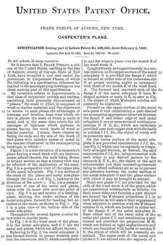
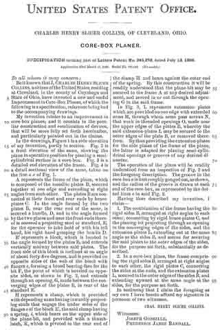
To all whom it may concern:
Be it known that I, CLIFFORD E. MARTIN, a citizen of the United States, residing at Greenfield, county of Franklin, State of Massachusetts, have invented certain new and useful Improvements in Core-Box Planes, of which the following is a full, clear, and exact description.
My invention relates to improvements in planes, and particularly to that type of plane termed a “core-box” plane.
The broad object of the invention is to provide a simple improvement in planes of the above type, by which improvement perfect segments of circles may be planed out with the greatest ease and accuracy. This feature of improvement and others will be more fully explained in the following description.
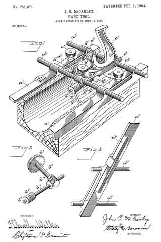
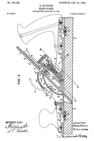
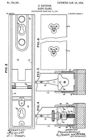
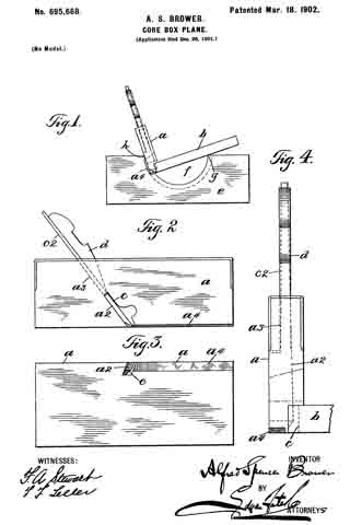
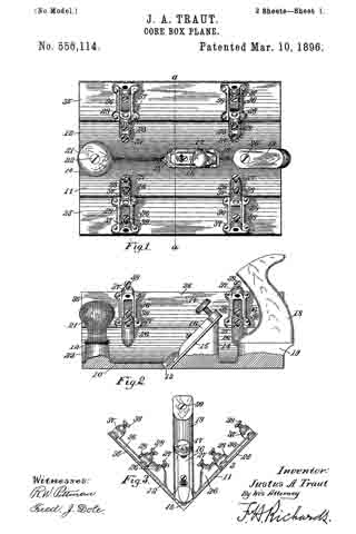
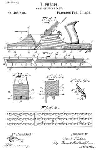
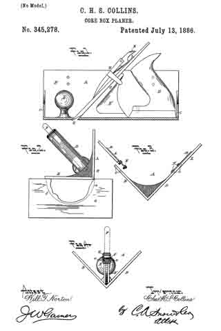
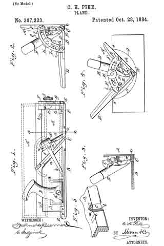
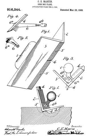
In the drawings, Figure 1 is a perspective view of the plane complete. Fig. 2 is a rear end elevation of the plane as it appears when actually in use. Fig. 3 is a front end elevation of the plane. Fig. 4 is a perspective view of certain details. Fig. 5 is a perspective view, partly broken away, of one of the details shown in Fig. 4.
The stock of the plane includes a suitable handle 1 connected to the main body, which latter includes the two side plates 2 and 3. The surfaces of these two plates are arranged in two planes intersecting each other at an angle of 90°.
4 is the plane iron. In this particular form the plane iron is arranged in a groove intersecting the surface of the plate 2, said groove being formed at a suitable rearwardly inclined angle relatively to the direction of movement of the plane iron during its cutting movement. The cutting edge of the plane iron is exposed at the meeting angle of the plates 2 and 3, and the groove in which the plane iron stands is preferably cut back at an oblique angle to the surface of plate 12 so that its cutting edge will be presented obliquely to the work, thus producing a draw-cut.
5 represents a clearance groove or recess formed in the side plate 3 and intersecting the meeting angle of plates 2 and 3, and of a width corresponding substantially to the width of the plane iron. This clearance groove 5 is of sufficient depth to provide for the proper thickness of shaving. The cutting edge of the plane iron, when properly adjusted, is coincident with the surface of plate 3 so that the extreme edge will be located accurately in one of the planes of the right angle.
A clamping device 6 is carried by the plane iron and passes longitudinally through the base of the handle 1 and wholly below the grip portion thereof. This clamping device has a hooked end 6a arranged to partially embrace the plane iron 4 as shown in Fig. 4.
6b is a suitable screw device arranged to engage the rear end of the body 6 of the clamping device, said screw device 6b being accessible at the rear end of the base of said handle. This clamping device 6 is arranged at an angle to the plane iron as shown in Fig. 4 so that when the adjusting screw 6b is set down the hooked end 6a of the clamping member will bind the plane iron firmly upon its seat.
As will new be seen, when the plane is used in the manner illustrated in Fig. 2, the cutting will be performed in such a way as to work out a groove of perfect semi-circular outline in cross-section. That part of the clearance groove 5 in front of the cutting edge of the plane iron permits the latter to encounter the material to be cut without projecting said cutting edge beyond or outside of the right angle. That part of the groove 5 to the rear of the plane iron operates to let the edge of the plane settle at each stroke whether or not said plane is drawn back sufficiently far to cause the plane iron to entirely clear the end of the groove. Thus short strokes may be employed to cut away tenacious portions of the wood. Were it not for this rearward extension of the clearance groove 5, the progress of the work would be very much impeded.
The usual throat to permit the escape of shavings is of course provided directly in front of the cutting edge of the plane iron through which chips and shavings will escape in the usual manner.
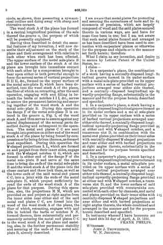
What I claim is:
1. In a plane of the character described, a stock having two diverging side plates the surfaces of which are arranged at an angle of 90 degrees relatively to each other, a plane iron having its cutting edge coincident with said angle and extending to one side thereof and in the plane of one of the side plates, and a clearance groove in said side plate extending forwardljv and rearwardly of the cutting edge of said plane iron.
2. In a core-box plane, a stock comprising two side plates the surfaces of which are arranged in planes intersecting one another at right angles, a clearance groove in one of said plates extending the full length thereof and coincident with the angle of intersection of said side plates, a plane iron carried by said stock, and means for detachably holding said plane iron in place, the cutting edge of said plane iron projecting into said clearance groove.
3. In a core-box plane, a stock including two side plates the surfaces of which are arranged in intersecting planes at right angles to each other, a groove in one of said sides intersecting the surface thereof for receiving a plane iron, a plane iron adapted to said groove, and rneans for detachably holding the same therein, a clearance groove in the surface of the other plate to the front and rear of the cutting edge of the plane iron and of a width corresponding substantially thereto.
4. In a core-box plane, two side plates the surfaces of which are arranged in planes intersecting each other at right angles, a clearance groove in one of said plates at and adjacent to the meeting angle of said planes and extending the full length of said side plate, a plane iron, and means for detachably holding the same, the cutting edge of said plane iron projecting into said clearance groove and being arranged to stand directly in one of said intersecting planes.
5. ln a plane of the character described, a stock having two diverging side plates the surfaces of which are arranged at an angle of 90° relatively to each other, a plane iron having its cutting edge coincident with said angle and extending to one side thereof and in the plane of one of said plates, and a clearance groove in said side piate extending forwardly and rearivardly of the cutting edge of the plane iron, a handle arranged in the angle between the two side plates, and a clamping device carried lay said handle and wholly below the grip portion thereof.
6. ln a plane of the character described, a stock having two diverging side plates, the surfaces of which are arranged at an angle of 90° relatively to each other, a plane iron having its cutting edge coincident with said angle and extending to one side thereof and in the plane of one of said side plates, and a clearance groove in said side plate forward of said cutting edge, a handle arranged in the angle between the diverging side plates, and a clamping mernber for the plane iron arranged in the base of said handle and accessible at the rear thereof for operation.
CLIFFORD E. MARTlN.
Witnesses:
ELLEN K. O’KEEFE,
FRANCIS NIMS THOMPSON.