No. 1,270,744 – Plane Attachment (Joseph O. Langford) (1918)

UNITED STATES PATENT OFFICE.
_________________
JOSEPH O. LANGFORD, OF EL PASO, TEXAS, ASSIGNOR OF ONE-HALF TO HENRY MOHR, OF EL PASO, TEXAS.
PLANE ATTACHMENT.
_________________
1,270,744. Specification of Letters Patent. Patented June 25, 1918
Application filed April 26, 1917. Serial No. 164,679.
_________________
To all whom it may concern:
Be it known that I, JOSEPH O. LANGFORD, a citizen of the United States, residing at El Paso, in the county of El Paso and State of Texas, have invented certain new and useful Improvements in Plane Attachments, of which the following is a specification.
This invention relates to planing tools and more particularly to an attachment therefor, in the nature of a guard or fender.
The principal object of the invention is to produce a guard for a plane-stock, whereby the hand of the operator is protected from injury by splinters, etc., during the use of the planing tool.
A further object of the invention is to produce a guard of this character which will prevent splinters and the like from striking the front ends of the side plates, and which may be readily attached to or detached therefrom whenever desired and with no difficulty whatsoever.
With these and other objects in view, my invention consists in the details of construction, arrangement and combination of parts, as will be hereinafter more fully described in the following specification and pointed out in the accompanying drawings, wherein:
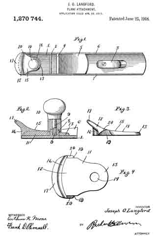
Figure 1 is a top plan view of a plane, with my attachment thereon, Fig. 2 is a longitudinal sectional view of the attachment and the end of the plane to which it is secured, Fig. 3 is a side view of the attachment shown detached from the plane, and Fig. 4 is a detail bottom plan view of the same.
Referring now more particularly to the several views of the drawings, it will be noted that my attachment is shown, in several instances, applied to a planing tool known in the art as a block or jack plane, although it is to be understood that the invention can be used equally well with any other type of plane.
In this particular instance, 1 indicates the flat lower surface of the plane stock provided with a cross brace 2 at one end and a handle 3 at the opposite end. This surface is further provided with a transversely extending slot 4 arranged in proximiity to the cross brace 2 and for the purpose of permitting the plane bit or cutting blade of the plane to extend therethrough for engagement with the surface to be planed. A suitable inclined support or rest 5 is arranged adjacent the slot 4 and is of the type usually employed for supporting the plane bit in its various adjustments through the slot 4.
Formed at the forward end of the plane stock and midway between the side walls 6 and 7 thereof, is a raised boss 8 having a threaded bore therein adapted to receive the threaded shank 9 of a knob 10. This knob constitutes a gripping means for the operator to permit him to control the movement of the plane while being used. When using the plane, the operator of course, propels it over the surface of the board, etc., by means of the handle 3, but it is well-known in the art that serious injuries have been occasioned by reason of the fact that large splinters have been forced into the hand which grasps the knob piece 10 during the movement of the plane, besides interfering with the proper manipulation of the planing tool. It is the object of my invention to overcome this objectionable feature and to provide a guard for the operator’s hand, so that the splinters will be deflected from engagement therewith.
In carrying out my invention I provide a shielding plate or guard 11 having an enlarged end 12 and a restricted end 13, the latter being provided with an opening 14 adapted to receive the raised portion 8 of the plane stock after the knob 10 has been unscrewed therefrom and the guard member attached to the plane in the manner illustrated to advantage in Fig. 2 of the drawings. The upper surface of the guard is inclined and projects forwardly beyond the rounded front edge 16 to provide an overhanging flange 17. The marginal edge of the restricted portion 13 is beveled as indicated at 18, said edge terminating abruptly on both side of the plate to provide parallel straight edges 19 for closely engaging the inner faces of the sides 6 and 7 respectively of the plane stock. Shoulders 20 are formed forward of the edges 19 for engagement with the front ends of the side walls 6 and 7 and are undercut as seen in Fig. 3 so as to conform to the curvature of said ends, thus permitting the guard member to be firmly seated in place when attached to the plane. The knob 10 when its shank 9 is screwed into the raised boss 8 will abut against the upper surface of the guard 11 and will securely retain the latter in position.
When using a planing tool with my attachment thereon, it is evident that any splinters which might normally tend to wound the hand of the operator grasping the knob 10, will be deflected therefrom by reason of the forwardly extending and overhanging guard. It will be seen that such splinters must necessarily engage the front edge 16 of the attachment and be turned aside by reason of the overhanging flange 17, consequently prevented from striking the front ends of the side walls or projecting in the direction of the knob, about which the hand is gripped. This attachment may be constructed of any suitable material adequate for the purpose in view, and may of course be so constructed as to be readily attachable to any type of plane in use. It is of most simple construction and can be applied to or removed from the plane without the necessity of changing the plane in any material particular.
Having thus described my invention what I claim as new and desire to secure by Letters Patent is :–
The herein described attachment for a plane whose stock comprises a flat bottom plate and upstanding side walls, the same consisting of a boss rising from said bottom plate and having a threaded cavity, and a knob having a threaded shank for engaging said cavity; combined with a guard plate having a restricted rear end with an opening passing over said boss, straight parallel side edges engaging the inner faces of said side walls, undercut shoulders forward of said edges resting upon the upper edges of the walls at the front ends of the latter, a transversely rounded front end flush with the front end of the bottom plate, and above it an overhanging flange, the whole for use substantially as described.
ln testimony whereof I affix my signature in presence of two witnesses.
JOSEPH O. LANGFORD.
Witnesses:
J. D. CÖPLENZ,
GEO. MILLER.
Copies of this patent may be obtained for five cents each, by addressing the “Commissioner of Patents, Washington, D. C.”
_________________


