No. 1,149,703 – Adjustable Knob For Planes (Bertel F. Vaughan) (1915)
UNITED STATES PATENT OFFICE.
_________________
BERTEL F. VAUGHAN, OF WEST HAVEN, CONNECTICUT, ASSIGNOR TO SARGENT & COMPANY,
OF NEW HAVEN, CONNECTICUT, A CORPORATION OF CONNECTICUT.
ADJUSTABLE KNOB FOR PLANES.
_________________
1,149,703. Specification of Letters Patent. Patented Aug. 10, 1915.
Application filed August 1, 1913. Serial No. 782,490.
_________________
To all whom it may concern:
Be it known that I, BERTEL F. VAUGHAN, a citizen of the United States, residing in the borough of West Haven and county of New Haven, State of Connecticut, have invented certain new and useful Improvements in Adjustable Knobs for Planes, of which the following is a full, clear, and exact description.
This invention relates to an improved construction of adjustable grip member or knob for planes or other devices where it is desired to set a knob or like member in any of a number of different inclined positions.
One of the objects of the invention is the provision of a grip member for planes, which is universally adjustable i. e. which can be tilted both transversely and longitudinally of the plane stock, and clamped in the position in which it will serve the operator’s purpose most conveniently. A tilting knob such as contemplated by my invention, can be used to particular advantage on smoothing planes, as it will enable the operator to grasp the plane in a manner conducive to the most accurate work.
Another object of the invention is to provide improved means for clamping the knob in its various adjustments. More particularly, it is aimed to provide a construction in which the knob may be released by turning it in one direction after which it may be swung into another position and clamped in that position by turning it in a direction opposite to that first mentioned.
To these and other ends, the invention consists in the novel features and combinations of parts to be hereinafter described and claimed.
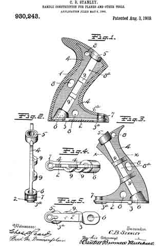
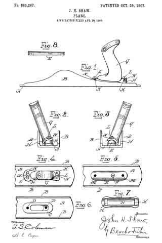
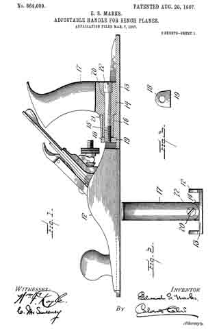
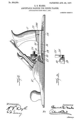
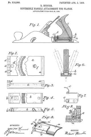
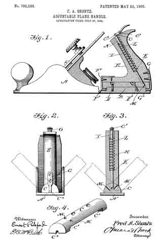
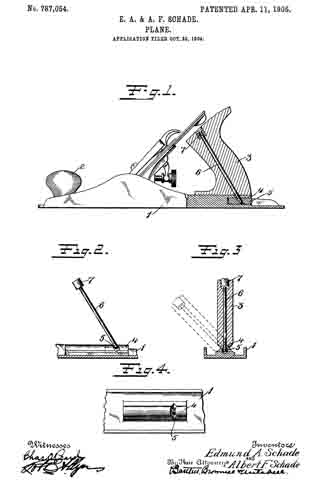
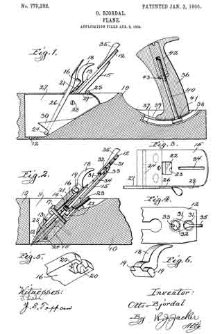
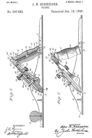
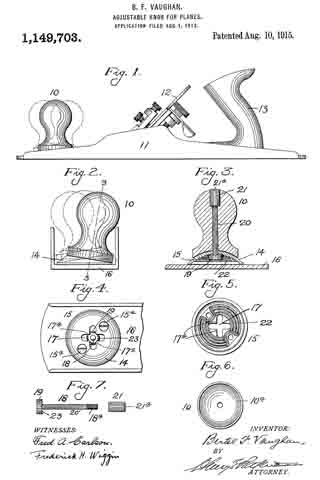
In the accompanying drawing, Figure 1 is a side elevation of a smoothing plane having a knob embodying my invention, Fig. 2 is an enlarged front elevation of Fig. 1 with certain parts omitted, Fig. 3 is a section on line 3–3 of Fig. 2, Fig. 4 is a top plan view of the forward end of the stock with the knob proper removed, Fig. 5 is a bottom view of the knob base, detached, Fig. 6 is a bottom plan view of the knob proper, and Fig. 7 is a detail view of the clamping bolt and nut.
Referring to the drawing, I have shown an adjustable knob 10 as applied to a smoothing plane having a stock 11, bit or cutter 12 and handle 13. The knob proper is of more or less usual outer configuration except at the bottom, which is made concave, as shown at 10a in Fig. 6, in order to fit the convex upper surface 14 of a knob base 15 on the bed or sole 16 of the stock. The base 15 is detachably applied to the upper surface of the bed or sole 16 of the stock by means such as fastening screws 15a. The base, which is formed as a portion of a sphere, has a diameter somewhat greater than that of the lower portion of the knob which rests on it, and at the center of the base the same is provided with a cruciform slot 17. A clamping bolt 18 has a head 19 located in the space beneath the base 15 and a shank 20 passing upward out of the slot 17 and through the knob. The head 19 of bolt 18 is too large to pass through the slot 17, and assemblage is effected by extending the shank of the screw upward through the base before the latter is secured to the stock by the screws 15a The upper portion of the knob is counterbored to receive a cylindrical nut 21 having interior screw threads engaging the threads 18a on the end of the shank 20.
The under surface of the base 15 is provided with a plurality of concentric ribs 22, and the upper surface of the screw head 19 is provided with a plurality of teeth 23 adapted to engage these ribs and also to engage the corners of the slot 17 whereby the knob may be tightly clamped in different adjustments when the nut 21 is screwed up sufficiently on the bolt 18.
It will be understood, that when the knob has its axis directed perpendicularly to the plane of the bed 16, the teeth 23 of the head 19 will interlock with the corners 17a of the slot 17 when the nut 21 is screwed up tightly on the bolt 20. To release the knob from this position, it is usually merely necessary to turn it in an anti-clockwise direction which will release the nut 21 by the frictional fit between said nut and its socket in the knob. Upon release of the clamping bolt the knob may then be shifted into any of a large number of inclined positions with the shank 20 of the bolt passing through the middle of the slot or through any one of the four corners thereof, and with the head 19 of the bolt engaged with the corners 17a of the slot or with the ribs 22. When the knob has been moved to the desired angular position, it may be tightened in that position by turning it in a clockwise direction; which movement will tighten up the nut 21 by virtue of the frictional fit of the latter in its socket in the knob. It will thus be understood that by the construction described, the knob is capable of universal adjustment. The dotted lines in Fig. 1 show two different adjustments of the knob in a direction lengthwise of the plane, and in Fig. 2, two different adjustments transversely of the plane are represented.
In case an especially tight clamping of the knob is desired, the nut 21 may be screwed up by a screw-driver fitting a nick 21a in said nut, and this screw-driver nick is also useful where difficulty is encountered in releasing the knob by hand in the manner described.
I do not limit myself in all aspects of the invention to a knob located in front of the cutter of the plane, and in some aspects of the invention it is not essential that a tilting knob located in front of the cutter be adjustable both transversely and longitudinally of the plane stock.
Without limiting myself to the construction shown, I claim:
1. The combination with a plane, of a universally adjustable grip member therefor; substantially as described.
2. The combination with a plane, of a tiltable knob therefor and means to clamp and release the knob by a turning movement thereof; substantially as described.
3. The combination with a plane stock, of a knob applied to said stock and tiltable transversely of the stock and longitudinally thereof; substantially as described.
4. The combination with a plane, of a detachable knob, and means for clamping the knob to the plane in any of a number of positions wherein the knob is tilted either transversely or longitudinally of the plane; substantially as described.
5. In a plane, a universally adjustable tilting knob, and means to clamp and release the knob; substantially as described.
6. In a plane, the combination of a stock, a cutter in the stock, a handle at the rear of the cutter, a tiltable knob in front of the cutter, and means to clamp and release the knob by a turning movement thereof; substantially as described.
7. The combination with a plane stock, of a concave-convex member detachably secured to the bed of said stock and having a slot therein, a knob resting on the upper convex surface of said member, a clamping device having a head confined between the bed of the stock and the under concave surface of said member, and provided with a shank passing upward through said slot into said knob, and a nut threaded on said shank to clampbthe knob in position; substantially as described.
In witness whereof, I have hereunto set my hand on the 30th day of July 1913.
BERTEL F. VAUGHAN.
Witnesses:
E. M. HORAN,
M. G. HIGGINS.
Copies of this patent may be obtained for five cents each, by addressing the “Commissioner of Patents, Washington, D. C.”
_________________