No. 161,516 – Improvement In Bench-Planes (William Johnstone) (1875)

[paiddownloads id=”240″]161516


UNITED STATES PATENT OFFICE.

_________________

WILLIAM JOHNSTONE, OF MONTREAL, CANADA, ASSIGNOR OF ONE-HALF HIS RIGHT TO WILLIAM WHITEHEAD ROBERTSON, OF SAME PLACE.

IMPROVEMENT IN BENCH-PLANES.

_________________

Specification forming part of Letters Patent No. 161,516, dated March 30, 1875; application filed March 1, 1875.

_________________

To all whom it may concern:

Be it known that I, WILLIAM JOHNSTONE, of the city and district of Montreal, in the Province of Quebec, in the Dominion of Canada, pattern-maker, have invented an Improvement on Bench-Planes, of which the following is a specification:

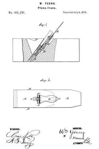
My invention relates to the adjustment of the plane-iron by means of a nut working on a screw, so that by simply turning the nut the plane-iron is drawn into or pushed out irom the body of the plane, and when at the desired place is held there firmly by a catch in the shape of an eccentric or cam, reference being had to the annexed drawings, where similar letters indicate like parts, and where —

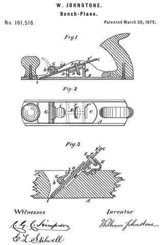
Figure 1 represents a sectional elevation of an iron plane embodying my invention. Fig. 2 represents a plan of Fig. 1. Fig. 3 represents a modification adapting it to wooden planes.

Letter A is the body of the plane, having two cross-bars or partitions, B B, formed in it, extending up to the under side of the plane-iron C, and of such height that the plane-iron is supported at the proper angle. In the bars B B, and extending from one to the other, is fixed, by any suitable means, a screw, D, on which is a flat nut, E, having its edge milled to adord a better hold and prevent the fingers or thumb of the person using it from slipping. This nut E passes through the slit F in the plane-iron C, and projects a short distance beyond it. The plane-iron C is held fast by the cam G. This cam is turned on the pin h by means of the handle i, and when in the position shown in the drawings by firm lines the projecting part k presses tight on the plane-iron C, and holds it firmly against the bars B B and the beveled edge of the hole l.

When it is desired to adjust the plane-iron the cam G is thrown up into the position shown by the dotted lines in Fig. 1. The plane-iron C is now free to be moved, which is done by placing the thumb or finger on the projecting part of the nut E and turning it round. This causes it to move up or down the screw D, and its side being in contact with the side of the slit F in the plane-iron C compels it to move in the same direction with it. When in the required position the cam G is turned down and holds it there.

The plane-iron C is provided with one or more additional slits, F’, to be used when it becomes shorter by the wearing away of its cutting-edge.

The modification shown in Fig. 3 consists of the piece H, of any suitable configuration, firmly secured to the wooden body of the plane in place of the bars B B to carry the screw D;
the remainder of the parts being the same as above described in connection with planes having bodies of iron, with the exception that a passage is cut through the projecting part k of the cam G, to allow the nut n. to pass when the plane-iron C is worn short.

By these arrangements I am enabled to adjust the plane-iron with greater nicety, and more easily and expeditiously than by the old method.

What I claim as my invention is —

The plane A, having bars B B, in combination with screw D, nut E, and plane-iron C, having slits F and F’, substantially as and for the purposes described.

WILLIAM JOHNSTONE.

Witnesses:
C. G. C. SIMPSON,
E. L. STILWELL.

No. 165,291 – Improvement In Plane-Irons (William Young) (1875)

[paiddownloads id=”246″]165291


UNITED STATES PATENT OFFICE.

_________________

WILLIAM YOUNG, OF MABON, NOVA SCOTIA.

IMPROVEMENT IN PLANE-IRONS.

_________________

Specification forming part of Letters Patent No. 165,291, dated July 6, 1875; application filed May 15, 1875.

_________________

To all whom it may concern:

Be it known that I, WILLIAM YOUNG, of Mabon, in Nova Scotia, have invented an Improvement in Plane-Iron, of which the following is a specification:

In the accompanying drawing, Figure 1 represents a vertical longitudinal section of plane-stock with my improved plane-iron, and Fig. 2 a bottom view of the iron.

Similar letters of reference indicate corresponding parts.

My invention relates to an improved mode of applying the cap-piece to the plane-iron so that it can be quickly adjusted and locked for giving the plane more iron, and thereby the annoying loss of time and the difticulty connected with the screw-locking be avoided.

The invention consists of a slotted plane-iron to which the cap-piece is locked by an eccentric lever pivcted to a post of the same.

In the drawing, A represents the plane-iron; and B, the cap piece, which is adjusted by a post, C, sliding in the longitudinal center slot D of the plane-iron to the required position for use. The post C is secured, by a counter-sunk base-plate, to the cap-piece. A locking-lever, E, with eccentric E’, pivoted to post C, swings to either side of the same, and locks, by the eccentricity of its sides, the cap to the iron when carried down on the latter, while admitting the ready setting when it is in a raised position. The plane-iron is fitted tightly in the stock by a wedge-key in the usual manner, the countersunk base-plate of the post of the cap-piece requiring no grooving of the key, and preventing thereby the settling of shavings and the choking of plane.

If desired, the cap may be provided with a series of grooves to lock with two teeth or ridges of the iron, by which the exact connection of cap and iron, without chance of changing their position on applying the lever, is retained.

Having thus described my invention, I claim as new and desire to secure by Letters Patent —

The combination of a plane-iron, having guide-slot, with the cap-piece, adjusted and secured by an eccentric lever pivoted to post of the same, substantially as and for the purpose set forth.

WILLIAM YOUNG.

Witnesses:
JAMES MURPHY,
EDW. D. TREMAIN.

No. 158,302 – Improvement In Bench-Planes (Carl Nordell) (1874)

[paiddownloads id=”236″]158302


UNITED STATES PATENT OFFICE.

_________________

CARL NORDELL, OF NEW YORK, N. Y.

IMPROVEMENT IN BENCH-PLANES.

_________________

Specification forming part of Letters Patent No. 158,302, dated December 29, 1874; application filed June 18, 1874.

_________________

To all whom it may concern:

Be it known that I, CARL NORDELL, of the city of New York, in the county and State of New York, have invented certain Improvements in Bench-Planes, of which the following is a specification:

The object of my invention is to furnish a hand-plane in which the tooth can be used shorter than in other planes, held in place and adjusted to the proper depth of cut and clearance for the shavings without the use of a double or covering tooth, or of the ordinary wedge, or the necessity of adjustment by hammering, and in which a durable metallic surface may be employed without liability of sticking to the surface of the work in consequence of the adhesion resulting from the well-known affinity between the metal and the rosin of the wood.

To accomplish this the invention consists, first, in a metallic cap, adjustable by means of a screw, or equivalent, to give the desired clearance for the shavings, and tightened against the tooth by means of a cam-lever pivoted to a screw adjusted in a threaded socket, which socket is pivoted on a spring-wire, or equivalent spring, which latter, held in permanent position at its two ends, allows ofa yielding at its middle to any extra or over pressure of the cam on the cap. This cap, with the cam-lever, thus does the purpose of the ordinary double or covering tooth and tightening-wedge. Second, in the combination of stationary springs with movable and adjustable screw-slides operating in the cap, and provided with cleats and stops, in such a manner that, when the cam-lever is thrown forward to loosen, but not remove, the cap, the tooth, which is provided with holes or slots suitable to encompass the said cleats, when the upper end of the tooth reaches the said stops, may be easily inserted between the said springs and the slides, and when pushed up against the said stops will be lodged on the said cleats by the pressure of the said springs, after which the depth of the tooth, or of the cut, is regulated. by operating the slides by means of its screws pivoted in the cap. When the cam is loosened the tooth may be instantly removed, when required, by simply pressing down the rear end of the cap against the ends of the springs placed under the tooth. This pressure raises the forward end of the cap sufficiently to release the tooth from the cleats, and allow it to slide out through the opening in the face of the plane. Third, in providing a combined metallic and wooden face of a plane by perforating or socketing the metallic face-plate, and inserting in the holes or sockets so formed one or more diffferent kinds of hard wood, placed with its grain or fibers at right angles to the face of the plane.

In the accompanying drawing, making a part of this specification, Figure 1 represents a longitudinal vertical section of a metallic hand-plane for planing wood, constructed according to my present invention. Fig. 2 is a face view of the same. Fig. 3 is a cross-section of the same, taken through the line x x of Fig. 1, and seen in direction of the arrow. Fig. 4 is a plan view of the under side of the tooth ofthe plane. Fig. 5 is a plan view of the inside of the cap, with its slides and screws for adjusting the tooth. Fig. 6 is a cross-section of the plane, taken through the line y y of Fig. 3.

Similar letters of reference indicate like parts in the different figures.

A are the wooden handles of the plane. B is the metallic face-plate, provided at each edge with upright flanges a1, between which are inserted and secured as well the handles A as the entire mechanism for operating the tooth. The face B is provided with numerous perforations or sockets, into which are tightly in serted the wooden pieces b’, made of any desired shapes and sizes, in such a manner as to form a perfectly smooth and even surface with the metal. C is a metallic frame for supporting the tooth, cap, springs, and sockets, severally above mentioned, and the screw for regulating the cap to give the desired clearance for the shavings. The frame C is provided on the outside with cleats c1 c2, and is of sufficient width outside of the cleats to snugly fill the space between the flanges a1, and is secured to the metal of the plane by entering the cleats c2 tightly between the two cleats a2 a3, formed on each side of the frame C upon the inner sides of the flanges a1, and is fastened at the bottom to the top of the metallic face-plate B by a pin, c3. The frame G may also be secured in any other suitable manner, the mode being immaterial so long as it be held firmly in its place. D are ribs or upright flanges of the frame C, upon which flanges the tooth rests when in position for work. A part of the lower portion of the frame C is formed into a socket, d1, placed across the face-plate of the plane, through which socket, and through holes in the lower part of the flanges D, is inserted a wire spring, d2, which spring also goes through and serves as pivot for the screw-socket E. This socket E is held in a central position in the frame C by being inserted through an oblong hole, e’, in the frame G, previous to the insertion, through the socket E, of the spring d2 The hole, being oblong, allows of an oscillating motion of the socket E, and thus also of a sliding motion of the cap. F are springs attached, with their lower ends, to the bottom of the frame C, and bearing, with their upper ends, against the under side of the tooth, to force the same, when being inserted, into its proper position against the cap, and retaining it there, even when the cap is partly released for adjustment of the cap or of the tooth. The upper cross-bar of the frame C is provided with a threaded hole for the reception of a thumb-screw, G, on which are formed a thumb-nut or milled wheel, g1, a shank, f1, and a button, g2. H is the cap, curved so as to touch with its forward end the lower or forward end of the tooth, whatever be the adjusted position of the cap. The rear end of the cap is formed into a downward-projecting flange, h1, in which is a slot, h2, fitting, when the cap is placed in position on the shank f1, between the thumb-nut g1 and button g2 of the screw G, the circumference of the thumb-nut g1 projecting far enough below the edge of the flange h1 to allow of turning the screw G, whereby the cap H is slid forward or withdrawn, according to the clearance desired for the shavings. In about the center of the cap H is a cup-shaped slotted socket for the reception of the spherical cam of the cam-lever I. This cam is slotted, and in its slot is pivoted the upper end of a screw, l’, the lower end of which enters the socket E. The cap H is also provided, at its upper or rear end, with slots h3, through which project, sufiiciently far to handle, the thumb-nuts j1 of the screws J. The forward ends of the screws J are pivoted in a rib, j2, forming a part of or attached to the cap H. The rear ends of the screws J are pivoted to the pieces i1, attached to the rear end of the cap H. On these pieces i1 are little projections i2, forming a cavity between them, for the reception of the rear ends of the springs F. K are slides, each threaded to form a nut, for the reception of one of the screws J, by turning which they are operated. Each slide K is provided with a cleat, k1, and a stop, k2. L is the tooth, the center of which is cut out so as to allow of its being slid back and forth without interfering with the screw I’ or socket E. In the rear ends of the tooth L are perforations l’, to receive, when the tooth is inserted, the cleats k1 of the slides K.

When the cam-lever is thrown in the position indicated by the dotted lines in Fig. 1, the springs F will raise the cap H sufliciently to allow (while slightly depressing the rear end of the cap H) of the introduction of the tooth L until it is checked by the stops k2 on the slides K. Allowing the springs F to expand, the tooth will be brought, with its slots l’, onto the cleats k1. By now turning either or both screws J, as the circumstances may require, by the hand-nuts j1, the tooth can be adjusted to the depth required, and its edge parallel to the face of the plane. The cap H is then adjusted by the screw G and hand-nut g1, to give the right clearance fbr the shavings. The cam-lever I is then tightened to depress the cap H, and the plane is ready for work.

Should the screw I’ have been turned down in its socket E too far for suiting a thicker tooth, the spring d2 will make up for the difference by yielding enough to allow of bringing the cam-lever down to the surface of the cap H in tightening the cam.

To remove the tooth it is only necessary to loosen the cam and depress slightly the rear end of the cap H.

Having thus described my invention, I claim as new and desire to secure by Letters Patent —

1. The cam and lever I, screw I’, and socket E, in combination with the spring d2, operating as described, and with the cap H, to hold the tooth firmly in place against the ribs D of
the frame C, substantially as specified.

2. The springs F, operating as described, in combination with the pieces i1 on the curved cap H, and the parts I I’ E, for the insertion and removal of the tooth L, and retaining the same while being adjusted, substantially as and for the purpose specified.

3. The screws J, working in the cap H, and provided with thumb-nuts j1, the slides K, with their cleats k1, and stops k2, in combination with the tooth L, provided with the slots l’, for the purpose of adjusting its position, substantially as and for the purpose specified.

4. The cap H, regulated by the screws G, the tooth L, regulated by the screws J and slides K, the cam and lever I, screw I’, socket E, and springs d2 F F, in combination with the frame C, face B, and handles A of a plane, to operate together in the manner and for the purposes substantially as specified.

5. The face of a plane, constructed by inserting pieces of wood b’ in a metallic face-plate, B, with the fibers at right angles to the face, substantially as and ibr the purpose specified.

The above specification of my invention signed by me this 15th day of June, 1874.

CARL NORDELL.

Witnesses:
D. PEARL,
H. W. E. PEARL.

No. 145,311 – Improvement In Plane-Irons (Ernest Quast) (1873)

[paiddownloads id=”222″]145311


UNITED STATES PATENT OFFICE.

_________________

ERNEST QUAST, OF JERSEYVILLE, ILLINOIS.

IMPROVEMENT IN PLANE-IRONS.

_________________

Specification forming part of Letters Patent No. 145,311, dated December 9, 1873; application filed February 18, 1873.

_________________

To all whom it may concern:

Be it known that I, ERNEST QUAST, of Jerseyville, in the county of Jersey and State of Illinois, have invented a new Improvement in Plane-Irons; and I do hereby declare that the following is a full and exact description of the same, reierence being had to the accompanying drawings, and to the letters of reference marked thereon.

This invention is a plane-bit having a shank of cast malleable iron, or common wrought-iron, and a removable cutting-edge of steel, the same constituting a new article of manufacture, as will be fully described hereafter.

In the drawing the plane-bit is shown in perspective.

A represents the upper section of the bit, of the usual form, and is made of iron, preferbly cast malleable iron. B is the cutting-part, made of suitable cast-steel. C is a screw or rivet, by which the parts are held together. a a’ are overlapping tongues, shaped to engage with each other, so as to form a scarf-joint of the two parts A and B. It will be seen that where the two parts A and B butt together at d and d’, the edge d is square, while d’ is beveled. Both may, however, be beveled, if so preferred.

When the steel part B is worn out, it can be quickly and easily removed by taking out the screw or rivet C. The part A, in consequence of being subject to but little wear, may thus be made to serve for almost an unlimited number of steel bits. It therefore follows that these plane-bits constructed as described, possess all the advantages of those made entirely of steel, and can be produced as cheaply as those made of steel and iron welded together, without that deterioration in the quality of the steel which is almost inseparable irom the process of welding.

Having fully described my invention, what I claim as new, and desire to secure by Letters Patent, is —

The plane-bit described, having the iron shank A and steel cutting-part B, as a new article of manufacture.

This specification signed and witnessed this 5th day of February, 1873.

ERNEST QUAST.

Witnesses:
JAMES A. LOCKE,
DENNIS BROWN.

No. 133,632 – Improvement In Carpenters’ Plane-Irons (Albert N. Cross) (1872)

[paiddownloads id=”205″]133632


UNITED STATES PATENT OFFICE.

_________________

ALBERT N. CROSS, OF NECEDAH, WISCONSIN.

IMPROVEMENT IN CARPENTERS’ PLANE-IRONS.

_________________

Specification forming part of Letters Patent No. 133,632, dated December 3, 1872.

_________________

To all whom it may concern:

Be it known that I, ALBERT N. CROSS, of Necedah, in the county of Juneau and State of Wisconsin, have invented certain new and useful Improvements in Carpenters’ Plane-Irons; and I do hereby declare that the following is a full, clear, and enact description thereof, that will enable others skilled in the art to which it appertains to make and use the same, reference being had to the accompanying drawing and to the letters of reference marked thereon which form a part of this specification.

The nature of my invention consists in a cap and case used with a plane-iron, and so constructed that the cap can be set or adjusted at any distance from the edge of the blade, and the two together raised or lowered in the case, as will be hereinafter more fully set forth.

In order to enable others skilled in the art to which my invention appertains to maize and use the same, I will now proceed to describe its construction and operation, referring to the annexed drawing, in which —

Figure 1 is a plan view, Fig. 2 a side view, and Fig. 3 a longitudinal section, of my invention.

A represents the plane iron or blade, B the cap, and C the case. The case C is in the center, on the front, provided with two slots, a and b, the slot a, extending from the upper edge downward for a suitable distance, and at the lower end of said slot is formed a projection, d, on the outside of the case. Below this projection d is the slot b, running on the same line with the former slot. The blade A is also slotted, as shown in Fig. 3, and is, with the cap B, placed in the case. A screw, e, is then passed through the slot b of the case and through the slot in the blade, and screwed into the cap B, thus securing the blade and cap firmly together. By means of the slot in the blade the cap may be set at any desired distance from the edge of the blade to do good work. On the front side of the blade A, at or near the upper end, is a short post or projection, f the outer end of which has a hole with female-screw threads. Through this is passed a thumb~screw, D, the lower end of which goes loosely through the projection d on the case, and has a nut on its end to prevent its being withdrawn. By means of this thumb-screw D the blade is raised or lowered at will for thin or thick shavings, and, the cap being fastened to the blade, the two are of course adjusted at the same time.

The case C is to be wedged in the stock so as to be firm in the same, the whole forming a very convenient and useful improvement in planes.

Having thus fully described my invention, what I claim as new, and desire to secure by Letters Patent, is —

The within-described plane-iron, consisting of the slotted blade A, cap B, and slotted case C, the blade and cap being adjusted together by the set-screw e placed within the case and operated by the thumb-screw D, in the manner and for the purposes herein set forth.

In testimony that I clairn the foregoing I have hereunto set my hand.

ALBERT N. CROSS.

Witnesses:
E. S. MINER,
B. F. BUCK, JR.

No. 64,341 – Improvement In Plane-Irons (S. Markee) (1867)

[paiddownloads id=”124″]64341


United States Patent Office.


S. MARKEE, OF AUBURN, NEW YORK, ASSIGNOR TO HIMSELF AND JOHN M. EASTERLEY, OF SAME PLACE.

Letters Patent No. 64,341, dated April 30, 1867.
_________________

IMPROVEMENT IN PLANE-IRONS.

_________________

The Schedule referred to in these Letters Patent and making part of the same.

_________________

TO ALL WHOM IT MAY CONCERN:

Be it known that I, S. MARKEE, of Auburn, in the county of Cayuga, and State of New York, have invented a new and useful Improvement in Plane-Irons; and I do hereby declare that the following is a full, clear, and exact description thereof, which will enable others skilled in the art to make and use the same, reference being had to the accompanying drawings, forming a part of this specification, in which —

Figure 1 is an under side view of the plane-iron, showing the sliding-nut.

Figure 2 is a longitudinal section of the same, taken through the line x x, fig. 1.

Figure 3 is a cross-section of the same, taken through the line y y, fig. 1.

Figure 4 is a detail sectional view, taken through the line z z, fig. 2, showing the under side of the sliding-nut.

Similar letters of reference indicate like parts.

My invention has for its object to furnish an inaproved double plane-iron, simple and cheap in construction, and convenient in operation; and it consists, first, in attaching the cap to the plane-iron by a screw and sliding-nut; and, second, in the sliding-nut in combination with the plane-iron cap and screw, as hereinafter more fully described.

A is the plane-iron, which has a longitudinal slot, as shown, for the passage of the screw B, which secures the cap C to the plane-iron. The upper end of this slot is enlarged so that the nut D can he passed through it.

The cap C is made of sheet steel, slightly curved in its lower part, as shown in fig. 2. Through this cap is made a hole for the passage of the screw B. The screw B passes through the cap C and through the slot in the plane-iron A, and screws into the sliding-nut D, as shown in fig. 2. This nut is made with a projecting part or flange, as shown in figs. 2, 3, and 4, which its into the slot formed in the plane-iron A, and slides along said slot in adjusting the cap C upon the plane-iron A. By this construction it is not necessary to make the cap C as heavy as it was formerly made, when it had to be made thick enough to receive and hold the screw that held the cap and plane-iron together. This construction enables me to place the head of the screw on the upper side of the plane-irons, making it much more convenient to adjust the cap in proper position with reference to the cutting edge of the plane-iron than when the head of the connecting-screw was on the under side of the plane-iron, as was the case when the cap and plane-iron were connected together in the ordinary manner.

What I claim as new, and desire to secure hy Letters Patent, is —

The plane-iron, consisting of the slotted iron A, curved cap C, flanged sliding-nut D, and screw B, arranged and operating substantially as described for the purpose specified.

The above specification of my invention signed by me this 7th day of March, 1866.

S. MARKEE.

Witnesses:
B. J. IVES,
R. P. STOW.

No. 114,085 – Improvement In Plane-Irons (Ira Almy And Sereno A. Drake) (1871)

[paiddownloads id=”184″]114085


United States Patent Office.


IRA ALMY AND SERENO A. DRAKE, OF COVERT, NEW YORK.

Letters Patent No. 114,085, dated April 25, 1871.
_________________

IMPROVEMENT IN PLANE-lRONS.

_________________

The Schedule referred to in these Letters Patent and making part of the same.

_________________

To all whom it may concern:

Be it known that we, IRA ALMY and SERENO A. DRAKE, both of Covert, Seneca county, State of New York, have invented certain new and useful Improvements in Plane-Iron, of which the following is a full, clear, and exact description, reference being had to the accompanying drawing making part of this specification, in which —

Figure 1 is a view of our improved plane-iron with the parts arranged in a proper working relation to each other, and Figure 2 is a detached view of the lower iron or bit with the cap removed.

Similar letters of reference denote corresponding parts in both figures.

The invention relates to the construction of double irons — that is, those composed of two parts — to wit: a lower or cutting~blade or bit, and an upper part or cap, this cap being attached to the bit by means of a screw.

These double irons are usually employed in jointing-planes and srnoothing-planes, when smooth and accurate work is required.

The invention consists in making the bit reversible, having both ends constructed with a cutting-edge, in combination with a cap having a longitudinal slot therein, as will be hereinafter fully explained.

In the drawing —

A represents the cap, made, preferably, of wrought or malleable iron, and substantially in the form of an ordinary single plane-iron, except that, when in proper position in the plane-stock, the bevel at the lower end is upon the upper side instead of on the lower side, as it is in a plane-iron.

This cap is provided with a long narrow slot, enlarged into a circular form at the upper end, to admit the passage of a screw, which will soon be described.

B is the bit or cutting-blade, made in the form shown plainly in fig. 2. Both ends of this bit are made in the same shape, so that they can be used for cutting-edges, and, in practice, we deem it advisable to make it entirely of steel.

C is a set-screw, the shank of which is adapted to engage with a thread cut in the central portion of the bit, as at b, fig. 2.

By preference we provide the bit with a rectangular rib, B’, of such a width as will allow it to slip into the slot c, and of a height a little less than the thickness of cap A.

The object of this rib B’ is to assist in maintaining the bit and cap in a proper relation to each other when they are connected by means of the screw, as in fig. 1, and more particularly for the purpose of adjusting the parallelism of the cutting-edge and the bottom or working face of the plane-stock; but, as this rib may not in all eases be found to he essential, we do not wish to be limited to its use.

The construction and operation of the device is so simple that a more detailed description is not deemed necessary.

Having now described the invention, What we claim as new, and desire to secure by Letters Patent, is —

The herein-described plane-iron, consisting of the cap A and the reversible bit B, substantially as shown and described.

IRA ALMY.
SERENO A. DRAKE.

Witnesses:
JAMES C. KNIGHT,
O. G. WHEELER.

No. 111,890 – Improvement In Joiners’ Planes (George Allen Warren) (1871)

[paiddownloads id=”178″]111890


UNITED STATES PATENT OFFICE.

_________________

GEORGE ALLEN WARREN, OF NORTH BRIDGEIVATER, MASSACHUSETTS.

IMPROVEMENT IN JOINERS’ PLANES.

_________________

Specification forming part of Letters Patent No. 111,890, dated February 14, 1871.

_________________

To all whom it may concern:

Be it known that I, GEORGE ALLEN WARREN, of North Bridgewater, of the county of Plymouth, of the State of Massachusetts, have invented a new and useful Improvement in Joiners’ Planes; and I do hereby declare the same to be fully described in the following specification and represented in the accompanying drawings, which show the invention applied to a plane, termed the “Bailey Plane,” it embracing one or more improvements patented by Leonard Bailey.

My invention, or lateral adjuster, as hereinafter described, is to enable a person to effect a lateral movement of a plane iron or bit in either direction, so as to adjust its cutting-edge in parallelism with the bearing-surface ofthe plane-stock.

Of the said drawings, Figure 1 denotes a longitudinal section of a plane with my invention applied to it. Fig. 2 is an under side view of the plane-iron or cutter, showing its longitudinal slot, which receives the eccentric of the lateral adjuster. Fig. 3 is a side elevation, and Fig. 4 a top view, of the eccentric and its operative milled head.

In such drawings, A denotes the plane-stock, and B the cutter or plane-iron, they being represented as provided with mechanism for adjusting the cutter longitudinally, and for clamping it down to its bed or bearing-sun face a.

The lateral adjuster is shown at b as consisting of a disk fixed eccentrically on a vertical journal, c, which goes through the bed at or near its upper part, and into the shank d of a milled head, e, the said journal and shank being held in connection by a clamp-screw, f. The eccentric enters the longitudinal slot g of the plane-iron, and has a diameter equal to the width of the slot. On revolving the eccentric more or less the plane-iron may be moved or tilted laterally either way, so as to bring its cutting-edge into proper adjustment with the bearing or lower surface of the plane-stock.

The devices for effecting the longitudinal adjustment of the plane-iron consist of a bent lever, C, and a screw, D, arranged and applied to the said iron and the stock in manner as represented, the devices for clamping the iron to the stock being the headed screw E, the slotted lever F, and the eccentric or cammed lever G, operating against a spring, H, all being as shown, and as commonly made and used in the Bailey plane.

I make no claim to anything, arrangement, or combination of devices as set forth and described in the United States Patent, No.67,398, to Bailey, or in the United States Patent, No. 64,790, to Palmer. My mechanism for effecting lateral adjustment of the bit or plane-iron and the application of such mechanism to the bit, or the arrangement of the adjusting mechanism with the slot of the bit and with the stock of the plane differs materially from anything represented or described in either of such patents, and is particularly advantageous or effective and simple in construction and application.

I claim —

1. The lateral adjuster, as described, as composed of the disk b, the journal c, the socketed shank d, with its clamp-screw and head, as set forth.

2. The arrangement of the said lateral adjuster, as described, with the bed of the stock, and with slot e of the plane-iron, all being substantially as and to operate as explained.

GEORGE ALLEN WARREN.

Witnesses:
R. H. EDDY,
J. R. SNOW.

No. 108,946 – Improvement In Caps For Plane-Irons (Charles N. Tuttle) (1870)

[paiddownloads id=”173″]108946


United States Patent Office.


CHARLES N. TUTTLE, OF AUBURN, NEW YORK.

Letters Patent No. 108,946, dated November 1. 1870.
_________________

IMPROVEMENT IN CAPS FOR PLANE-IRONS.

_________________

The Schedule referred to in these Letters Patent and making part of the same.

_________________

I, CHARLES N. TUTTLE, of Auburn, Cayuga county, New York, have invented certain new and useful Improvements in Caps for Plane-Irons, of which the following is a specification.

Heretofore, in the manufacture of steel caps for plane-irons, it has been usual to forrn the raised hub that enters the elongated-slot of the cutter-iron, and that receives the confining and adjusting-screw, from the body of the cap itself, by swaging up such hub; but this is quite an expensive process, and necessitates the heating to a greater degree, and for a longer time, of the cap.

My object is to cheapen the construction of the cap and manufacture it by a simpler process; and

My invention consists in a cap having a metallic hub secured thereto by brazing, and which is afterward provided with a screw-thread, and thus forms an improved cap.

In the accompanying drawing —

Figure 1 represents, in perspective, my improved cap;
Figure 2, a. top view;
Figure 3, longitudinal central section; and
Figure 4, a longitudinal central section of a modified form.

A represents the cap of a double plane-iron, which is to be formed of steel; but, instead of swaging up a hub on the surface of the cap, I am enabled to do entirely away with such action by simply cutting off from a strip of smooth iron of proper width and thickness a length suitable for a hub, B, and this I secure to the surtitce of the cap, which I am enabled to make irom the regular rolled steel or iron, by means of brazing.

It will be evident to those skilled in the manufacture of these articles that it is a great desideratum to be able to use the regular rolled steel or iron, and have simply to cut it off the proper length, turn the corners, and round up and sharpen the Iower edge, thus obviating the heating and working of but one end.

The cap and hub are provided with a hole either after or before brazing the hub to the cap, which is provided with a thread to receive a confining and adjusting-nut, C’, which I prefer to make of malleable iron on account of cheapness and durability.

Instead of brazing the hub directly to the surface of the cap, I may punch a hole of suitable size through the cap, and in this hole place a hub of at thickness necessary to fill up such opening, and also project the proper distance above the cap to form a hub, as in fig. 4, and this hub I brazed in or to the opening in the cap.

In all cases where a hub is formed or secured to the cap by swaging, the hub has afterward to be dressed square on the sides; but with a hub previously squared in its manufacture, and then brazed, this tedious and rather expensive portion of the manufacture is avoided.

Having described my invention, I claim —

The plane-iron cap, provided with a nut when each is formed in separate pieces, and brazed together, as and for the purpose herein specified.

C. N. TUTTLE.

Witnesses:
C. W. UPHAM,
C. N. TUTTLE, Jr.

No. 64,001 – Improvement In Plane Irons (William H. Eckert) (1867)

[paiddownloads id=”123″]64001


United States Patent Office.


WILLIAM H. ECKERT, OF SYRACUSE, NEW YORK.

Letters Patent No. 64,001, dated April 23, 1867.
_________________

IMPROVEMENT IN PLANE IRONS.

_________________

The Schedule referred to in these Letters Patent and making part of the same.

_________________

TO ALL WHOM IT MAY CONCERN:

Be it known that I, WILLIAM HENRY ECKERT, of the city of Syracuse, Onondaga county, New York, have invented a new and improved Plane; and I do hereby deciare that the following is a full, clear, and exact description of the same, reference being had to the annexed drawings, making a part of this specification.

The letters used represent corresponding parts wherever they occur.

To enable others skilled in the art to make and use my invention, I will proceed to describe the same, and its form when complete and ready for use.

Figure 1 represents a perspective view of the plane irons when put together.

Figure 2 represents the cap.

Figure 3 represents a cross sectional view of both the plane irons, with the nut and screw.

In the common form of plane irons the screw is made to pass directly into the cap, for the purpose of holding the two irons together. This form of construction involves the necessity of unscrewing the cap when-ever the irons are separated for sharpening, or any other purpose of separation. The object of my invention is to dispense with this necessity and enable the irons to separate by simple handling.

I make the cutting iron A in all respects in the common form, with an elongated slot, a, for the movement of the screw s, and with a circular aperture, o, for the screw-head to pass through. Instead of inserting the screw in the cap, I make the nut n, which may be in any convenient form, square, oblong, circular, or other-wise; but I consider the oblong form the best, because best calculated to bold the cap straight with the cutting iron. In the cap C I make the slot or opening h, into which the nut n is made to fit, and it should be so made as to receive the nut with a snug joint. By this means the cap C, which in other respects is made in the common form, is readily adjusted by means of the screw and the irons, separated by slipping the cap C off from the nut n.

What I claim as my invention, and desire to secure by Letters Patent, is —

The nut n, in combination with the planing iron A, the screw s, and the cap C, made and operated substantially as and for the purposes described.

I also claim the slot h in the cap C, when made to it upon the nut n, and applied to planing irons, substantially as described.

WM. H. ECKERT.

Witnesses:
N. B. SMITH,
G. W. SMITH.

No. 72,443 – Improvement In Carpenters’ Planes (Leonard Bailey) (1867)

[paiddownloads id=”134″]72443


United States Patent Office.


LEONARD BAILEY, OF BOSTON, MASSACHUSETTS.

Letters Patent No. 72,443, dated December 24, 1867.
_________________

IMPROVEMENT IN CARPENTERS’ PLANES.

_________________

The Schedule referred to in these Letters Patent and making part of the same.

_________________

TO ALL PERSONS TO WHOM THESE PRESENTS SHALL COME:

Be it known that I, LEONARD BAILEY, of Boston, in the county of Suffolk, and State of Massachusetts, have invented a new and useful Improvement in Bench-Planes; and I do hereby declare the same to be fully described in the following specihcation, and represented in the accompanying drawings, of which —

Figure 1 is a top view, and Figure 2, a longitudinal section of a plane-iron and its cap-iron, and their holding-devices, such cap-iron being constructed in accordance with my improvement.

Figure 3 is a longitudinal section of the plane-iron and cap-iron, as ordinarily constructed, that is to say, with one bend, a, only near the bearing-edge of the cap-iron.

My object is to use very thin steel plane-irons, and in so doing I find that they are liable to buckle under the pressure of the cap, which causes them to chatter, and makes them otherwise imperfect; and my invention consists in the providing of an auxiliary point of contact between the cap and plane-iron, and at the point where the plane-iron tends to buckle or rise from its bed or base, and thus have a pressure at that point in addition to that at the cutting-edge, which firmly holds this thin plane-iron to its bed.

The cap-iron, as commonly constructed, that is, as shown at D, in fig. 3, when applied to the plane-iron E, will rest thereon only at the extreme lower end of the cap-iron, and also at or very near its upper end. There will be along angular space, b, between the two irons, when they are clamped together by the holding-devices which are represented in figs. 2 and 3, at A, B, and C, and consist of a screw, A, a bearing, B, and a cam-lever, C, arranged in a manner well known.

The dfficulty experienced from the construction of the cap-iron with the single bend a, is, that it allows of vibration of the cap-iron and the plane-iron while in use, such vibration being productive of what joiners term “chattering,” and consequent defective operation of the plane.

In carrying out my improvement, I make the cap-iron with an additional bend, b, (see figs. 2 and 3,) at a short distance back of its lower end or toe, or at a distance therefrom equal to about double the distance at which such lower edge or toe is to be from the main bend a, or the toe of the bearer B, the same being as shown in figs. 2 and I, so as to cause the cap-iron D’ to bear on the plane-iron E’ in three places, or at the toe and auxiliary bend of the cap-iron, and along from such bend to the heel or upper end of the cap-iron. This construction or formation of the cap-iron D’ completely obviates the difficulty above mentioned, and is a very valuable and useful improvement.

In all bench~planes the plane-iron must project slightly beyond its bed or bearing, the edge of the bed beyond which it projects serving as a fulcrum to the force of the pressure ofthe cap upon the extreme edge of the plane-iron. When thick plane-irons are used, their stiffness may resist the pressure of the cap sufficiently to prevent buckling or rising of the plane-iron from its bed; but in thin steel plane-irons which I use, the pressure of the cap upon the projecting portion of the plane~iron causes this portion to yield slightly, and of course produces buckling at some point behind, and generally close to the fulcrum. To prevent this buckling or rising, and still use the thin steel plane-irons, I put an extra bend in the cap, so that it shall have a point of impact with the thin steel at the place where it tends, from the pressure on its projecting edge, and the fulcrum behind that edge, to risefrom its bed, and thus I effectually prevent “buckling” and “chattering,” whilst I can avail myself of the economy of thin steel for the plane-irons.

What I claim as my invention, and desire to secure by Letters Patent in the adaptation of thin steel to the plane-irons of bench-planes, is —

The auxiliary point of impact between the cap and the thin plane-iron, at the point or portion thereof where the thin steel tends to buckle under the pressure of the cap upon the projecting edge of the plane-iron, substantially in the manner described.

LEONARD BAILEY.

Witnesses:
R. H. EDDY,
F. P. HALE, Jr.

No. 65,604 – Improvement In Forming Projections On The Caps Of Plane-Irons (Napoleon B. Reynolds) (1867)

[paiddownloads id=”128″]65604


United States Patent Office.


NAPOLEON B. REYNOLDS, OF AUBURN, NEW YORK.

Letters Patent No. 65,604, dated December 18, 1867.
_________________

IMPROVEMENT IN FORMING PROJECTIONS ON THE CAPS OF PLANE-IRONS.

_________________

The Schedule referred to in these Letters Patent and making part of the same.

_________________

TO ALL WHOM IT MAY CONCERN:

Be it known that I, NAPOLEON B. REYNOLDS, of Auburn, in the county of Cayuga, and State of New York, have invented certain new and useful improvernents in the Manner of Making or Forming the Projection or Swell on the Cap of Plane-Irons, and which is used instead of a loose nut for holding the screw-bolt that secures the cap to the plane-iron; and that the following is a full, clear, and exact description of the manner of doing the same, reference being had to the accompanying drawings, making a part of this specification, in which —

Figure I represents at view from the back of the plane-iron, showing the slot therein and the bolt passing through it into the cap.

Figure 2 represents a cap with a hole punched through it for the reception of the button which afterwards forms the swell, projection, or nut for the screw-bolt to take into.

Figure 3 represents a section through the cap, and showing the countersinking of the hole that is to receive the button.

Figure 4 represents a section through the cap after the button or swell is fastened thereto.

Figures 5 and 6 show a top and edge view of one of the buttons before it is inserted in the hole in the cap.

Figure 6 shows the form of the swell, button, projection, or nut after it has been riveted in the hole in the cap.

Similar letters of reference, where they occur in the several separate figures, denote like parts in all the drawings.

I am aware that a swell or projection has been proposed on the cap of a plane-iron as a substitute for the ordinary loose nut heretofore used. I do not claim the swell or projection. My invention consists in the manner or means of producing this projection, which I do in a very cheap and very durable manner, without rolling down the metal or heat-welding it.

To enable others skilled in the art to make and use my invention, I will proceed to describe the same with reference to the drawings.

At manufacturing establishments where boilers are made are to be found and procured at very cheap rates, and of the very finest quality of iron, any quantity of burrs or buttons that are punched out of the plates of which the boilers are made for rnaking rivet holes. These burrs or buttons can be procured at a rate but little above that of old iron, and are therefore very cheap, whilst they have the form, body, and flange or fin that peculiarly fits them for my purpose.

The cap A I propose to make of steel, and a hole, a, having been punched through, it is then countersunk or reamed out at each side of the plate or cap, as shown more distinctly in fig. 3. I then take one of the burrs or buttons 6 and insert it in the hole a in the cap. The fin or flange c which is on the burr or button, and left there by the punch that drove it out of the boiler-plate, fits into the countersink on one side of the hole, and the burr or button projects through and beyond the other face of the cap. In this position the cap and burr are placed under a drop-die, one blow of which rivets the button or burr in the hole, and it is afterwards dressed up to the proper shape or form for entering the slot in the plane-iron, and for preventing the cap from turning on the plane-iron, whilst it can move longitudinally of it. When the riveting on of the button is accomplished, as explained, the burr or button will have assumed the form shown at fig. 7, and also in fig. 4, and be as immovably fixed thereto as though it were a part of the same metal with the cap itself.

As a matter of economy I should always use the burrs or buttons made by punching boiler-plates, yet I would regard it as my invention if these burrs were especially punched out for the purpose herein named.

Having thus fully described my invention, what I claim therein as new, and desire to secure by Letters Patent in forming a swell or projection on the cap of a plane-iron, is —

The method of construction substantially as described.

N. B. REYNOLDS.

Witnesses:
I. W. QUICK,
T. R. HUSSY.