No. 940,324 – Oil-Cup For Planes (David James) (1909)

[paiddownloads id=”666″]940324


UNITED STATES PATENT OFFICE.

_________________

DAVID JAMES, OF COFFEYVILLE, KANSAS.

OIL-CUP FOR PLANES.

_________________

940,324. Specification of Letters Patent. Patented Nov. 16, 1909.
Application filed June 22, 1907. Serial No. 580,239.

_________________

To all whom it may concern:

Be it known that I, DAVID JAMES, citizen of the United States, residing at Coffeyville, in the county of Montgomery and State of Kansas, have invented new and useful Improvements in Oil-Cups for Planes, of which the following is a specification.

My invention relates to improvements in oilers for planes.

The object of my invention is to provide a device of the character described, in which the lower face of the plane can be supplied with the proper amount of oil, and by which the oil supply opening can not be filled with dirt and prevent the proper operation of the oiler. Neither will the oil run from the oil cup when the plane is inverted.

Another object of my invention is to provide a more simple, cheap and effective oiler of this character to accomplish the result desired.

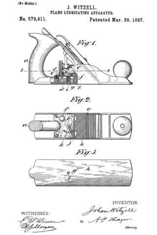
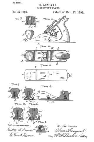
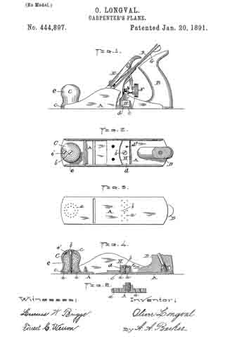
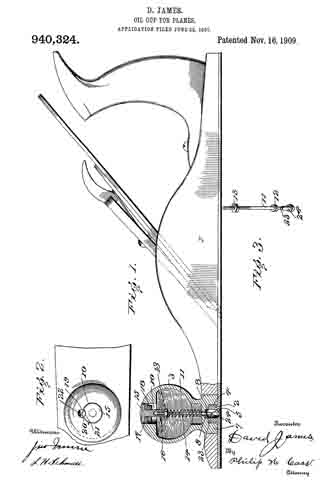
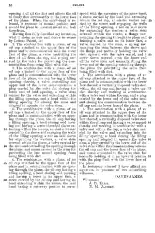
ln the accompanying drawings: Figure 1 is a longitudinal vertical sectional view of a plane, showing my improved oiler applied thereto; Fig. 2 is a top plan view of the plane partly broken away; and Fig. 3 is an enlarged detached view of the valve showing the several parts removed or separated from each other.

Referring now to the drawings, 1 represents a plane which is of the ordinary structure and having the usual boss 2 adjacent its forward end to which is attached an ordinary knob 3 for operating the same. In my improved oiler, this knob forms the oil cup, and, as shown, is of a spherical shape and hollow so as to receive and hold the oil. As shown, the boss 2 is externally screw-threaded and the oil cup provided with an internally screw-threaded opening 4, which is screwed upon the boss. The said boss is provided with a central opening 5 which extends through the lower face of the plane 6 and through which the oil passes to the lower face of the plane. The oil cap has an inwardly extending flange 7 which extends over the upper end of the boss and is provided with an opening 8 corresponding with the opening 5 in the boss. The said opening, at its upper end, is provided with an annular flange 9, the lower face of which forms the seat for the valve, as will be hereinafter more fully described.

The upper end of the oil cup is provided with an enlarged opening 10 through which the oil is placed in the cup and in which the operating button is placed. Within the oil cup is a vertically disposed valve stem 11 which extends downwardly through the opening within the flange 9 and below the same has rigidly secured thereto a valve 12, which, as shown, is of a circular form and fits firmly against the lower face of the flange 9 and forms a tight joint to prevent the escape of oil from the cup. The stem 11, adjacent its upper end, is screw-threaded and screwed thereon is a nut 13. Coiled upon the stem, below the nut, is a coil-spring 14 which has its lower end bearing upon the flange 9 and normally forces the valve stem upwardly and holds the valve firmly to its seat.

Screwed upon the extreme upper screw-threaded end of the valve stem is a head 15 which is of a size approximating that of the opening 10 and is provided with a reduced externally threaded sleeve 16 extending within the oil cup. Carried by this sleeve is a washer 17, preferably of leather, which engages the walls of the opening 10 and prevents the oil from leaking therefrom. Below the washer and carried by the sleeve is a nut 18 which is adapted to expand the washer and insure a perfect fit with the walls of the openings.

In order to prevent the screw-head from turning and accidental displacement from the valve stem, I provide the upper face of the oil cup, adjacent the opening 10, with an annular recess 19, having a screw-threaded opening into which is screwed a flat-headed screw 20, and the screw-head 15 is provided with a recess 21 into which the flat-headed screw 20 extends and prevents the head from turning. The head of the screw has a curved cut-away portion 22 which, when turned in its proper position, allows the head to be turned.

The valve stem 11 has its lower end screw-threaded at 23 and screwed thereon is a sleeve nut 24, the head portion of which fills the opening 5 in the boss and prevents the dirt, etc., from filling this opening 5. By turning this nut, it will be seen that the same can be adjusted so that it will hit a slight distance above the lower face 6 of the plane.

By pushing upon the screw-head, it will be seen that the valve stem is forced downwardly against the tension of the spring and the valve is unseated. The sleeve nut is likewise carried downwardly clearing the opening 5 of all the dirt and allows the oil to freely flow downwardly to the lower face of the plane. When the screw-head is released, it resumes its normal position and should the plane be inverted no oil will leak therefrom.

Having thus fully described my invention, what I claim as new and desire to secure by Letters Patent, is:

1. The combination with a plane, of an oil cup attached to the upper face of the plane and in communication with the lower face of the plane, a valve controlling the flow of oil from the cup, and a plug carried by the valve for preventing the communication from being filled with dirt.

2. The combination with a plane, of an oil cup attached to the upper face of the plane and in communication with the lower face of the plane, the cup having a filling opening therein, a valve controlling the upper end of the lower communication, a plug carried by the valve for closing the lower end of said opening, a valve stem carried by the valve and extending within the filling opening, and a head within the filling opening for closing the same and adapted to operate the valve stem.

3. The combination with a plane, of an oil cup attached to the upper face of the plane and in communication with an opening through the plane, the oil cup having a filling opening, a head closing said opening and having a screw-threaded sleeve extending within the oil-cup, an elastic washer carried by the sleeve and engaging the walls of the filling opening, a nut on said sleeve for expanding the washers, a valve stem screwed within the sleeve, a valve carried by the stem and controlling the opening through the plane, and means carried by the stem for preventing the last named opening from being filled with dirt.

4. The combination with a plane, of an oil cup attached to the upper face of the plane and in communication with an opening through the plane, the oil-cup having a filling opening, a head closing said opening and having a recess in its upper face, a screw carried by the oil-cup and having its head extending within the recess, the said head having a cut-away portion to correspond with the curvature of the screw-head, a sleeve carried by the head and extending within the oil cup, an elastic washer carried by the sleeve and engaging the walls of the filling opening, a nut on said sleeve for expanding the washer, a valve stem screwed within the sleeve, a flange surrounding the opening through the plane and forming a valve seat on its lower face, a valve carried by the stem, a spring surrounding the stem between the sleeve and the flange and normally holding the valve stem upward with the valve seated, and a screw sleeve screwed upon the lower end of the valve stem and normally filling the lower end of the opening extending through the plane for preventing the same from being filled with dirt.

5. The combination with a plane, of an oil cup attached to the upper face of the plane and in communication with the lower face thereof, a vertically disposed valve stem within the oil cup and having a valve carried thereby and working in combination with a valve seat within the cup, and a plug carried by the lower end of the valve stem and closing the communication between the oil cup and the lower face of the plane.

6. The combination with a plane, of an oil cup attached to the upper face of the plane and in communication with the lower face thereof, a vertically disposed valve stem within the oil cup and having a valve carried thereby and working in combination with a valve seat within the cup, a valve stem carried by the valve and extending into the filling opening, a head closing the filling opening and adapted to operate the valve stem, a plug carried by the lower end of the valve stem within the communication between t.he oil cup and the lower face of the plane, and means connected to the valve stem for normally holding it in an upward position with the plug flush with the lower face of the plane.

In testimony whereof I have affixed my signature, in presence of two subscribing witnesses.

DAVID JAMES.

Wittnesses:
J. B. ELLIS,
N. M. JANSSEN.

No. 579,911 – Plane-Lubricating Apparatus (Johan Witzell) (1897)

[paiddownloads id=”528″]579911


UNITED STATES PATENT OFFICE.

_________________

JOHAN WITZELL, OF NEW YORK, N. Y.

PLANE-LUBRICATING APPARATUS.

_________________

SPECIFICATION forming part of Letters Patent No. 579,911, dated March 30, 1897.
Application filed June 13, 1896. Serial No. 595,434. (No model.)

_________________

To all whom it may concern:

Be it known that I, JOHAN WITZELL, a citizen of the United States,and a resident of New York city, in the county and State of New York, have invented certain new and useful Improvements in Plane-Lubricating Apparatus, of which the following is a specification.

My invention consists of improved means of periodically supplying lubricating-oil to the working face of the plane, as hereinafter described, reference being made to the accompanying drawings, in which —

Figure 1 is a side elevation of a wood-plane with a part in section, showing the application of my improved lubricating apparatus. Fig. 2 is a horizontal section of the plane on line 2 2, Fig. 1. Fig. 3 is a plan of the plane inverted.

Between the handle a and the seat b of the plane-bit c I provide an oil-reservoir d in any approved way with a suitable cover e, said cover having a plugged filling-aperture, as indicated at f, and I provide a lubricating-passage g through the bottom of the reservoir to the working face h of the plane with a valve i to open and close the same, said valve being on the lower extremity of a vertical stem j, extending up through the cover and thereat provided with a horizontal lever-arm j, normally extending from the stein located midway between the sides of the plane or thereabout to the right-hand side and inclined forward relatively to the lengthwise direction of the plane, about as represented in Fig. 2, so that it is convenient to engage the arm with one of the fingers of the hand holding the plane by the handle and working the plane and pull the arm backward to open the valve, which being thus pulled back is made to raise and open the valve by the curved inclined way k, which I have provided on the cover e for such effect.

Within the reservoir and between the cover e and the valve-top I have provided a coiled spring l, which presses downward on the valve and closes it when the arm j is released by the operator, the declivity of the way k being such that pressure of the spring will cause the arm to slide on it freely.

It will be seen that with my improved apparatus the supply of oil can be controlled at will and without interrupting the work. It will also be seen that the location of the lubricator between the seat of the plane-bit and the handle is more favorable for uniform lubrication of the working face throughout its entire length than when located in the knob forward of the bit. Besides the knob so utilized is not as reliable and serviceable for withstanding the hammer-shocks for jarring the bit slack as when solid and the shocks of the hammer are liable to force out spurts of oil.

I claim —

In a plane-lubricator, the combination of the reservoir located between the seat of the plane-bit and the rear handle of the stock, and having a passage communicating with the working face of the plane, the valve seated in said passage and having a stem extending upward through the cover of the reservoir, spring arranged between the cover and the head of the valve for closing said valve, the inclined way on the cover of the reservoir, and the arm of the valve-stem ranging over said inclined way in the relation to the handle for opening the valve by a finger of the hand gripping said handle substantially as described.

Signed at New York city, in the county and State of New York, this 11th day of May, A. D. 1896.

JOHAN WITZELL.

Witnesses :
CHARLES BRETTELL,
GEORGE BRETTELL.

No. 556,608 – Oiling Attachment (Theodore Martin Anderson) (1896)

[paiddownloads id=”526″]556608


UNITED STATES PATENT OFFICE.

_________________

THEODORE MARTIN ANDERSON, OF NEW WHATCOM, WASHINGTON.

OILING ATTACHMENT.

_________________

SPECIFICATION forming part of Letters Patent No. 556,608, dated March 17, 1896.
Application filed March 8, 1895. Serial No. 541,035. (No model.)

_________________

To all whom it may concern:

Be it known that I, THEODORE MARTIN ANDERSON, of New Whatcom, in the county of Whatcom and State of Washington, have invented a new and Improved Oiling Attachment, of which the following is a full, clear, and exact description.

This invention relates to certain improvements in oiling or lubricating attachments, and has for its object to provide an attachment of this character especially designed for application to carpenters’ planes and the like to reduce the friction between the plane and the wood being dressed.

The invention will be hereinafter fully set forth and its novel features carefully defined in the claim.

Reference is to be had to the accompanying drawings, forming a part of this specification, in which similar figures of reference indicate corresponding parts in all the views.

Figure 1 is a vertical longitudinal section taken through a plane of ordinary construction provided with my improvements. Fig. 2 is a transverse section taken through the oil-chamber in the plane indicated by the line 2 2 in Fig. 1. Fig. 3 is a side elevation showing the device for regulating the attachment. Fig. 4 is a view similar to Fig. 1, showing another form of my invention. Fig. 5 is a transverse section in the plane indicated by the line 5 5 in Fig. 4. Fig. 6 is a view similar to Fig. 4, illustrating still another modified form of the device. Fig. 7 is a transverse section in the plane indicated by the line 7 7 in Fig. 6, and Fig. 3 is a transverse section showing another modification which will be hereinafter described.

Referring primarily to Figs. 1, 2 and 3, 1 represents a plane of any preferred construction having a bit 2 and provided with parallel upwardly-extending side pieces or flanges and having at its rear part, behind said bit, an oil-chamber 3, having an outlet 4. extending across the under side of the plane-stock. As clearly seen in Figs. 1 and 2, the receptacle or chamber 3 for the oil is provided with a cover 7 arranged to slide in grooves 6 6 formed in the opposite side pieces of the plane.

The chamber or receptacle 3 will be filled with any suitable lubricating material — as for example, cotton waste or wool saturated with oil — and a wick 5 of any suitable kind is arranged in the said chamber, adapted to extend with its lower end through the outlet 4 to the under side of the stock. In order to adjust this wick 5, I employ disks 3 having spurs, said disks being mounted on a shaft 9 extending through the chamber 3 and provided at one end with a thumb-piece 10 arranged in a recess 10a in the outer face of the plane, as clearly seen in Figs. 2 and 3. By this construction it will be seen that when it is desired to use the attachment the thumb-piece 10 may be turned to move the wick down into contact with the surface of the wood to be dressed, and the oil will flow through the said wick and become evenly distributed over the lower face of the plane so as to reduce the friction.

When it is not desired to use the attachment, the thumb-piece 10 may be turned in a reverse direction so as to raise the wick 5 above the under side of the plane, as shown in Fig. 1.

In the construction seen in Figs. 4 and 5 I employ in lieu of the disks 8 and shaft 9 an eccentric 15 mounted on a shaft 12 and arranged to work in a slot formed in a block 16, having a serrated edge adapted to engage and hold the wick 5. The shaft 12 is screw-threaded to receive a nut 14 to hold the block 16 in place, and is provided at its outer end with a thumb-piece 13. Thus it will be seen that as the thumb-piece 13 is turned the block 16 will be moved up and down in the oil-chamber 3, carrying with it the wick 5.

In the construction seen in Figs. 6 and 7 the chamber 3 is provided with a slot 11 in its rear wall, and in said chamber is pivoted at 13 a lever 17, the rear end of which projects through the slot 11. The forward end of the lever 17 is bifurcated, and in its bifurcations is journaled a roller 19 having a wearing-surface covered with cloth or the like, and the periphery of said roller 19 extends through an opening in the bottom of the oil-chamber 3 into contact with the surface of the wood to be dressed. Behind the chamber 3 is located a spring 20, the arms of which are bent up and adapted to hold the projecting rear end of the lever 17, whereby said lever, when depressed to stop the flow of oil, will be held in its depressed position. In this form of the attachment the receptacle 3 is provided with a hinged cover 7x.

It is not essential that the wick employed in the construction shown in Figs. 1 and 4 shall extend entirely across the under side of the plane-stock. In some cases the chamber 3 may be provided with a series of outlets 4x as indicated in Fig. 8, and each of these outlets may be provided with a separate wick 5x, as will be readily understood. If desired, the wick may be in front of the bit instead ef behind the same, as shown.

From the above description of my invention it will be seen that the same is capable of considerable modification, and for this reason I do not wish to limit myself to the precise construction herein shown.

Having thus described my invention, I claim as new and desire to secure by Letters Patent —

A plane having a base portion formed with parallel and perpendicular sides having a block arranged between them and arising from the base portion, and a bit mounted between said sides and supported by the block, the block having an oil-chamber therein, substantially as described.

THEODORE MARTIN ANDERSON.

Witnesses:
H. H. ELLS,
G. H. BACON.

No. 518,823 – Lubricator (Royal W. McIntyre And Gustavus A. H. Sprague) (1894)

[paiddownloads id=”507″]518823


UNITED STATES PATENT OFFICE.

_________________

ROYAL W. McINTYRE AND GUSTAVUS A. H. SPRAGUE, OF REDLANDS, CALIFORNIA.

LUBRICATOR.

_________________

SPECIFICATION forming part of Letters Patent No. 518,823, dated April 24, 1894.
Application filed January 23, 1893. Serial No. 459,385. (No model.)

_________________

To all whom it may concern:

Be it known that we, ROYAL WARNER McINTYRE and GUSTAVUS ADOLPHUS HANKINSON SPRAGUE., of Redlands, in the county of San Bernardino and State of California, have invented certain new and useful Improvements in Oil-Cups; and we do hereby declare the following to be a full, clear, and exact description of the invention, such as will enable others skilled in the art to which it appertains to make and use the same.

Our invention is an improvement in oil cups or cans designed for greater simplicity and durability of construction and efficiency and certainty of operation.

A further object of our invention is to supply simple and useful means for lubricating the under surface of iron planes thereby dispensing with the old method of greasing the under surface of the plane with a piece of fat.

Other objects and advantages of the invention will appear in the following description in which we have set forth fully the details of construction and the essential features thereof and illustrated them in the accompanying drawings in which similar letters of reference designate corresponding parts.

Figure 1 represents a part section and side view of an ordinary plane with our invention attached. Fig. 2 is a modification.

Reference being had to the above figures A represents the main body of the oil cup which is secured to the forward portion of the plane B by means of the hollow threaded lug C. The bottom of the cup A is provided with the conical hole D the smaller end of which is at the upper surface of the bottom. The upper portion of the cup A is furnished with a convex screw cap E which is made of light spring material and is screwed to the cup in the manner shown in Fig. 1. Extending upward through the conical hole D is the valve rod F one end of the stem of which is screwed to the projection G on the under surface of the cap E while its other end terminates in a conical enlargement H corresponding to the opening in the lower surface of the cup A. It will be readily seen that when the cap E is pressed downward the valve stem F and enlargement H are forced downward thus allowing the oil to flow through the hole in the bottom of the cup A thereby lubricating the under surface of the plane.

In Fig. 2 we have changed the construction slightly and instead of the conical hole D we have substituted a hole with parallel sides and constructed the enlargement H to correspond. In this latter construction the cup is adapted to be filled through the opening in the side of the cap near the top which is closed by a screw J. It will be readily seen that it is impossible for the oil to escape from the nozzle unless the base of the can is forced inward.

The construction and arrangement of the several parts of our invention being thus made known the operation and advantages of the same will it is thought be readily understood.

Having thus fully described our invention, what we claim, and desire to secure by Letters Patent, is —

The combination with a plane, having an opening through the bed of the front portion thereof, of an oil cup resting on said bed, and having a spring actuated valve therein which is operated from the upper end, and a screw plug, C, seated within the perforated base of the cup with an opening therethrough by means of which the said oil cup is secured to the bed plane, the upper portion of said plug being formed with an enlarged chamber, with which said valve communicates, and a lower reduced opening, and the lower end of said plug extending only partially through the side of the plane, substantially as described.

In testimony whereof we have signed this specification in the presence of two subscribing witnesses.

R. W. McINTYRE.
G. A. H. SPRAGUE.

Witnesses:
NAT A. BLAKE,
O. A. MOSTLING.

No. 471,391 – Carpenter’s Plane (Oliver Longval) (1892)

[paiddownloads id=”485″]471391


UNITED STATES PATENT OFFICE.

_________________

OLIVER LONGVAL, OF WORCESTER, MASSACHUSETTS, ASSIGNOR
OF ONE-FOURTH TO FREDERICK C. WALTON, OF SAME PLACE.

CARPENTER’S PLANE.

_________________

SPECIFICATION forming part of Letters Patent No. 471,391, dated March 22, 1892.
Application filed March 2, 1891. Serial No. 383,449. (No model.)

_________________

To all whom it may concern:

Be itknown that I, OLIVER LONGVAL, of the city and county of Worcester, and State of Massachusetts, have invented certain new and useful Improvements in Carpenters’ Planes and I do hereby declare that the following is a full, clear, and exact description thereof, reference being had to the accompanying drawings, forming a part of this specification, and in which —

Figure 1 represents a side view of a carpenter’s plane embodying my improvements. Fig. 2 is a horizontal section through the handle, showing a top or plan view of the plane with the knife and the usual holding parts thereof detached to more fully illustrate that part of my improvements coming under the same. Fig. 3 is a bottom view of the plane. Fig. 4. is a vertical longitudinal section through the parts shown in Fig. 2. Figs. 5, 6, and 7 represent different modifications in the construction of the front oiler of the plane, which will be hereinafter more fully described. Fig. 8 is a vertical section of the rear oiler and part of the bed of the plane, taken on line a, Fig. 2; and Fig. 9 is an enlarged horizontal section through part of the plane-bed and one end of said rear oiler, showing the inlet to the oil-chamber and its detachable stopper or plug, taken on line 19, Fig. 1.

With the exception of the oiling devices hereinafter described, the plane is of ordinary construction.

The purpose of my invention is to improve upon the means heretofore employed for oiling the bottom of the plane; and it consists in certain improvements in the construction of said oiling devices foreffecting the above result.

In order that others may better understand the nature and purpose of said improvements, I will now proceed to describe the same more in detail.

In the drawings, A represents the bed, B the front handle, C the rear handle, D the knife or blade, E the knife-holding cap, F the adjusting-screw, and G the lever, of an ordinary plane. The rear oiling device H is preferably located on the bed between the base of handle C and the knife and its supporting parts. It is constructed by forming a transverse rib or projection c on the top of and integral with the bed between the vertical side flanges d d thereof. Within said transverse projection is formed a chamber c’ for holding the oil, which chamber is provided with an opening at one end through which to pour in the oil and with a series of small vertical openings e, through which said oil is discharged to oil the bottom of that portion of the plane coming back of the throat I. The inlet to chamber c’ is provided with a suitable screw or plug f and washer f’ to prevent the oil from passing out at said point, while the small vertical discharge-openings are provided with wood plugs e’, preferably of pine or similar soft porous wood, to properly control the outflow of oil.
Said wood plugs I find in practice permit just sufficient oil to pass out to oil the bottom of the plane properly and without waste of oil, the plane when thus oiled running smooth and easy upon the most objectionable surfaces. The essential feature which I claim as new in this part of my invention is the formation of the oiler integral with the bottom or bed of the plane and providing the chamber with an end opening and plug, so that the chamber may be more conveniently opened from the outside of the plane, as shown, in filling the same.

The use of wood plugs in the discharge-openings I am aware is not new, the same being shown and claimed in the United States Patent to Edward F. Gordon, No. 213,104, dated March 11, 1879, and I therefore make no claim, broadly, thereto.

The front handle B constitutes a part of the oiling device for oiling the front end of the plane, and said device is constructed as follows: A metal base B’, made in the form of an inverted cup, so as to form a chamber B2 between the same and the bed when fitted in position, is provided with a vertical central stem g, projecting up, and over which is fitted the knob or handle B. A downwardly-projecting central screw h is also formed on the base, which is adapted to be screwed into a correspondingly-shaped vertical opening formed in the bed, whereby the base is fastened to said bed. The stem g may be made with a threaded surface, so that the knob B may be screwed on, as shown in Fig. 4, or smooth, so that said knob may be driven on, as shown in Figs. 5 and 6.

The oil is preferably supplied to chamber B2 through an opening formed vertically through the stem g and connecting with said chamber through suitable openings at each side of the screw h, as is shown in Figs. 4 and 5. I do not limit myself, however, to forming the oil-inlet in the stem g as aforesaid, as a like result may be effected by means of a plugged inlet, as g’, in the body of base B’, as is shown in Fig. 6.

In case a wood knob or handle B is used, it is preferable to employ an internally-threaded tube i in the opening which receives the stem g to produce a more durable construction, as is shown in Fig. 7.

In the constructions shown in Figs. 4 and 7 the handle or knob serves as the stopper for preventing the oil from passing out through the supply-opening, while in Fig. 5 a screw-plug or nut j is employed for that purpose, a screw being formed on the plug, which may be screwed into the oil-inlet, which is threaded at its upper end for the purpose. In Fig. 6 a reverse construction is adopted, a threaded opening being formed in the plug to receive a screw formed at the upper or outer end of the stem; but said stem does not in this instance serve as an oil-passage, the nut j being used for holding the knob B in place. In each case an elastic or other suitable washer k is preferably used at the oil-inlet under the knob or plug to make the same oil-tight, and a suitable washer l is also used for the same purpose between the base B’ and bed A. In like manner to the other oiler, a series of vertical discharge-openings are formed in said bed for the front oiler last described, formed within the circumference of the bearing-point of the base against the bed, which openings are also provided with wood plugs e’, as in the former instance.

My improvement in the front oiling device consists in the combination of the separate and detachable knob B and base B’ and the special construction adopted in connection therewith and the plane-bed for effecting the desired result.

I am aware of the United States Patents to W. Wood, No. 191,393, dated May 29, 1877, and 471,391 to L. A. Dearth, No. 363,213, dated May 17, 1887, both for planes, and I make no claim to the constructions therein set forth and shown.

What I claim as new, and desire to secure by Letters Patent, is —

1. In a carpenter’s plane, the bed having a transverse chamber c’ formed therein open at the end having a series of vertical openings or outlets through the bed to the bottom of the plane, in combination with a suitable plug or stopper having a washer under the same for closing the aforesaid end opening and wood plugs for closing the vertical openings, while at the same time permitting a certain quantity of oil to discharge through the latter, substantially as and for the purpose set forth.

2. In a carpenter’s plane, the bed having a series of vertical openings in its front end filled with wood plugs, as described, in combination with the base B’, made cup-shaped to form an oil-tight chamber between the same and the bed when fitted thereto, with a washer between it and said bed, also having a downwardly-projecting screw part for securing said base to the bed and an upwardly-projecting stem fitting in a knob or handle B, said knob or handle, and means for supplying oil to the chamber in the base, as well as for closing the supply-opening thereto oil-tight, substantially as and for the purpose set forth.

3. In a carpenter’s plane, the bed having a series of vertical openings in its front end filled with wood plugs, as described, in combination with the base B’, made cup~shaped to form an oil-tight chamber between the same and the bed when fitted thereto, with a washer between it and said bed, also having a downwardly-projecting screw part for securing said base to the bed and an upwardly-projecting stem having a threaded tube or sleeve over the same, as well as having a vertical opening therein connected with the chamber in base B’ and fitting in the knob or handle B, said knob or handle, and a washer interposed between the same and the end of the stem, substantially as and for the purpose set forth.

OLIVER LONGVAL.

Witnesses:
ALBERT A. BARKER,
W. B. NOURSE.

No. 444,897 – Carpenter’s Plane (Oliver Longval) (1891)

[paiddownloads id=”470″]444897


UNITED STATES PATENT OFFICE.

_________________

OLIVER LONGVAL, OF MILLBURY, MASSACHUSETTS.

CARPENTER’S PLANE.

_________________

SPECIFICATION forming part of Letters Patent No. 444,897, dated January 20, 1891.
Application filed April 5, 1889. Serial No. 306,093. (No model.)

_________________

To all whom it may concern:

Be it known that I, OLIVER LONGVAL, of Millbury, in the county of Worcester and State of Massachusetts, have invented certain new and useful Improvements in Carpenters’ Planes; and I do hereby declare that the following is a full, clear, and exact description thereof, reference being had to the accompanying drawings, forming a part of this specification, and in which —

Figure 1 represents a side view, partly in section, of a carpenters plane embodying my improvements. Fig. 2 is a horizontal section through the handle, showing a plan of the plane with all the old detachable parts removed to more fully illustrate my improvement. Fig. 3 is a plan of the bottom of the plane. Fig. 4 is a central vertical longitudinal section through the parts shown in Fig. 2, and Fig. 5 is an enlarged view showing a vertical section through a part of the plane-bed.

My invention relates more particularly to metal planes, but is also applicable to other styles of planes; and it consists in combining with the plane-bed oiling devices for supplying the bottom thereof with a proper amount of oil or other lubricating material to render the operation of planing more easy to perform, as hereinafter more fully set forth.

In order that others may better understand the nature and purpose of my said invention, I will now proceed to describe it more in detail.

In the drawings, the part A represents the bed of the plane, designed to be made of metal in the class of planes shown.

B is the main rear handle, and C the front-handle.

D is the blade or knife, E the holding-cap, and F and G the thumb-screw and lever, respectively, for adjusting said blade or knife.

As my invention relates only to the oiling devices, previously referred to, of the plane, it will be unnecessary to give a detailed description of said old parts.

I accomplish the desired result — viz., of oiling the bottom of the plane and the surface of the stock operated upon — by combining an oil-receptacle H with the bed of said plane back of the knife and other detachable parts connected therewith, and by converting the usual front handle into an oil-receptacle, the same being made hollow for the purpose, as is shown in Fig. 4. The oil is allowed to pass out of said receptacles for the above purpose through suitable openings a, made in the plane-bed A. The receptacles are filled with cotton waste or other suitable material saturated with oil, as is common in other oil-receptacles, and consist of the inverted detachable cups d e, which are provided with suitable plugged inlets d’ e’ for supplying the oil thereto, and having the screws b passed vertically through the same into the bed A for holding them in position.

The detachable cups d e of the oil-cups are made oil as well as air tight where they connect with the plane-bed, as well as where the holding-screws b thereof pass through, by means of suitable elastic washers or “packings” c. The motion of the plane over the surface being operated upon produces just sufficient suction to draw out the required amount of oil to produce the desired result, and the discharge thereof is facilitated by making the discharge-openings tunnel-shaped or flaring upward, as is best shown in Fig. 5. Said form of openings also obviates the liability to their becoming clogged or stopped by dust and other particles entering and becoming lodged therein. As above constructed, such particles, if they enter, are allowed to pass up and spread out into the oil, and therefore do not materially interrupt the outflow of said oil. Although it is preferable in practice to thus form the openings a, I do not limit myself thereto, but reserve the right to employ such shapes as are suitable for the purpose.

I am aware of the United States Patents to W. Wood, No. 191,393, dated May 29, 1877; E. F. Gordon, No. 213,104, dated March 11, 1879, and to L. A. Dearth, No. 363,213, dated May 17, 1887, and make no claim to any of the constructions therein set forth.

Having now fully described my invention, what I claim therein as new, and desire to secure by Letters Patent, is —

In a carpenter’s plane, the combination, with the plane-bed A, having a series of vertical openings a, therein, of detachable cups d and e, having suitable plugged inlets d’ e’ and fitted over said openings a, in the bed, the fastening-screws b, passed vertically through the oil-receptacles into the bed, the absorbent material contained within the oil-receptacles, and the packings c, interposed between the under side of the heads of the fastening-screws and the oil-receptacles and between said oil-receptacles and the top of the bed, substantially as and for the purpose set forth.

OLIVER LONGVAL.

Witnesses:
A. A. BARKER,
W. B NOURSE.

No. 363,213 – Hand Or Jack Plane (Lester A. Dearth) (1887)

[paiddownloads id=”422″]363213


UNITED STATES PATENT OFFICE.

_________________

LESTER A. DEARTH, OF LACONIA, NEW HAMPSHIRE.

HAND OR JACK PLANE.

_________________

SPECIFICATION forming part of Letters Patent No. 363,213, dated May 17, 1887.
Application filed March 25, 1887. Serial No. 232,399. (No model.)

_________________

To all whom it may concern:

Be it known that I, LESTER A. DEARTH, of Laconia, in the county of Belknap and State of New Hampshire, have invented certain new and useful Improvements in Hand or Jack Planes, of which the following is a specification.

My invention relates to jack or hand planes, and has for its object to provide improvements in devices of that kind whereby the sole of the plane may be oiled (as is necessary in some classes of work) during the operation of smoothing or planing lumber therewith, and without the necessity of stopping work and employing a device separate from the plane itself for that purpose.

As is well known to carpenters, joiners, and others skilled in arts requiring the use of planes, it is essential in many kinds of work to oil the sole of the plane, and in instances where this thing is necessarily frequent much time is consumed thereby, as well as annoyance occasioned to the workman.

In carrying out my invention I utilize the knob secured to the upper face of the stock just in front of the slot provided for the escape of shavings as an oil-reservoir, in addition to its present uses, and combine means with said knob whereby the workman can from time to time, and while using the plane in the ordinary manner, supply oil to the sole thereof as may be needed.

I will now proceed to describe my invention, so that others may be able to make and use the same, reference being had to the accompanying drawings, and to the letters of reference marked thereon, forming a part of this specification, the same letters indicating the same parts wherever they occur, and the invention being particularly pointed out in the claims hereunto appended.

Of the drawings, Figure 1 represents a perspective view of a plane having my improvements applied thereto. Fig. 2 is a longitudinal vertical section thereof.

A indicates the plane-stock, provided with the usual handle, B, and cutting iron or tool C, adjustably secured to operate in the slot D, provided for that purpose and for the escape of shavings.

E represents the knob applied to planes as new commonly constructed, which knob is attached to the stock just in front of slot D. I construct knob E of metal or other suitable material and make it hollow, as represented in Fig. 2, providing the interior with a short tube, e, extending up from a central point at the bottom thereof, and form a hole of desired size in the top over tube e, the hollow of which latter feature extends through the bottom of the cup.

f represents a stem adapted to fit closely in tube e and to slide thereon, a spiral spring, g, surrounding said stem above tube e, and bearing at its lower end on the upper end of said tube and pressing at its upper end against a pin, h, extending through the stem, whereby the stem f is pressed upward in the tube, pin i, extending from the stern through a slot, j, in the tube, serving to limit both the upward and downward movement of the stem.

k represents a plug constructed to closely fit and slide in the hole formed in the upper end of the knob, as aforesaid, and adapted to be screwed into the upperend of stem f, or otherwise connected therewith, which plug serves both as a stopple to the hollow knob and affords means for gaining access to the interior thereof and as a contrivance whereby stem f may be depressed against the tension of spring g, operating as hereinabove explained.

f’ represents a packing of any suitable character arranged in a groove formed in plug k, or between two disks comprising the same, whereby the plug may be made to fit the hole in which it works in an oil and air tight manner. A small hole or bore, l, is made in stem f which hole extends vertically upward for a short distance from the lower end thereof, and then horizontally outward through the side of the stem, and a hole, m, is formed through the side of tube e, at the lower end thereof, constituting a valve, all as clearly represented in Fig. 2, the construction and arrangeinent of these last mentioned features being such as that when stem f is depressed by bearing on plug k bore l will be brought into range with hole m, and oil with which it is designed to fill knob E (made into a cup, as explained) will flow through said bore and down through a hole, n, formed in the stock to the sole of the plane — in the present instance shown to be just ahead of the cutting-tool.

The manner of using the invention will now be readily understood. The knob being filled with oil and the parts being arranged in position, as shown, the operator from time to time, as it may be necessary to oil the plane, as aforesaid, and without stopping his work, depresses stem f for a moment by pressing a thumb or finger thereon, releasing a drop or so of oil, which runs down through hole n, in the stock to the proper point on the sole of the plane.

By the means explained a material amount of time is saved to the workman, and by utilizing the knob common to nearly all classes or kinds of planes my invention is made cheap of construction and ready of application, as well as convenient in use.

Although I have been particular to describe the precise form and arrangement of the parts as here comprising my improvements, it is obvious that these may be varied within the limits of mechanical skill without departing from the nature or spirit of my invention.

Having thus described my invention, what I claim is —

1. In a plane, the combination, with the stock, of the knob thereon, made hollow or formed as an oil-cup, a valve in said knob or cup, and a spring-pressed stem or plug extending to the exterior of the knob, whereby the valve may be operated to release oil from the cup to oil the sole of the plane, as set forth.

2. In a plane, the combination. with the stock, of the knob thereon, made hollow or formed as an oil-cup and provided with the tube e, having hole m, and spring-pressed stem, f fitted to slide in said tube and provided with bore or hole l, substantially as set forth.

In testimony whereof I have signed my name to this specification, in the presence of two subscribing witnesses, this 19th day of March, 1887.

LESTER A. DEARTH.

Witnesses:
STEPHEN S. JEWETT,
S. E. BLACKSTONE.

No. 213,104 – Improvement In Lubricators (Edward F. Gordon) (1879)

[paiddownloads id=”301″]213104


UNITED STATES PATENT OFFICE.

_________________

EDWARD F. GORDON, OF CONCORD, NEW HAMPSHIRE, ASSIGNOR TO HIMSELF AND JOHN A. WHITE, OF SAME PLACE.

IMPROVEMENT IN LUBRICATORS.

_________________

Specification forming part of Letters Patent No. 213,104, dated March 11, 1879; application filed January 17, 1878.

_________________

To all whom it may concern:

Be it known that I, EDWARD F. GORDON, of Concord, in the county of Merrimack and State of New Hampshire, have invented a new and Improved Lubricator, of which the following is a specification:

Figure 1 is a side elevation, partly in section, of a plane having my improved lubricating device attached. Fig. 2 is a face view of the same. Fig. 3 is a plan view of a portion of a planer-bed containing my improvement. Fig. 4 is a transverse section taken on line x x in Fig. 3.

My invention relates to lubricators for hand-planes and the beds of planers, molding and scraping machines, or for other metallic surfaces requiring lubrication.

The invention consists in holes or cavities formed in the surface to be lubricated, said cavities being filled with wood or other unyielding porous material saturated with oil. The cavities are either wholly filled with wood or partly filled, so as to leave a chamber for containing oil.

This improvement is especially designed for lubricating metallic surfaces that are moved over wood surfaces, or over which wood surfaces are moved, in the processes of wood-working.

Referring to the drawings, A is an ordinary iron hand smoothing-plane, in the face of which a recess or cavity, b, is formed, into which is driven a piece of wood or other suitable porous material, c, which partly fills it, leaving the chamber c’ for containing oil. The grain of the wood runs at right angles to the face of the plane, so that the capillary tubes of the wood may draw from the oil-chamber a suflicient quantity of oil to constantly lubricate the face of the plane or the surface upon which the plane is moved, thereby obviating the sticking and friction which are common to metallic planes. The upper wall of the oil-chamber is apertured and provided with a screw-plug, d, for the purpose of filling.

In Figs. 3 and 4, B represents a portion of the bed or presser-bar of a planing, sticking, or scraping machine, in which there is an oil-chamber, C. In the upper surface of the bed there are slots e, that communicate with the oil-chamber C. In these slots pieces of wood f are driven, so that the grain is at right angles to the face of the bed, and their upper ends are even with the face of the bed, while their lower ends extend downward and dip into the oil contained by the chamber C. The oil-chamber is provided with a filling-aperture, g, which is closed by a screw-plug, h.

In some cases the oil-saturated wooden plugs or pieces may entirely fill the cavities in the surface to which the lubricator is applied, as the wood will contain a sufficient quantity of oil to lubricate the surface for a considerable time.

I do not limit or confine my improvement to any particular form or proportions, nor to its application to any special tool or machine, as it may he made in various forms, and is applicable to tools and machines of every sort in which wood is moved in contact with a metallic surface, or the metallic surface is moved in contact with the wood, in the processes of wood-working. It may also be applied with advantage to metal-working machines and to metal surfaces working in contact.

I am aware that it is not new to fill recesses in the faces of planers with wood or soap-stone and without any lubricant; also, that it is not new to use a reservoir filled with oil that is fed by a wick or leather conductor; but the latter soon exhausts the oil and soils the stock that is being worked. Mine, on the contrary, always presents a hard, smooth surface, and feeds just a sufficient trace of oil to lubricate without soiling the stock; hence,

What I claim is —

The combination, in wood-working machinery, of the oil-reservoir b and the wooden plug c, the latter having its grain at right angles to the working-face of the planer, scraper, or molder, as shown and described.

EDWARD F. GORDON.

Witnesses:
GEORGE H. MILLS,
CHAS. H. BUXTON.

No. 191,393 – Improvement In Bench-Planes (Watson Wood) (1877)

[paiddownloads id=”278″]191393


UNITED STATES PATENT OFFICE.

_________________

WATSON WOOD, OF CHELSEA, MASSACHUSETTS.

IMPROVEMENT IN BENCH-PLANES.

_________________

Specification forming part of Letters Patent No. 191,393, dated May 29, 1877; application filed February 26, 1877.

_________________

To all whom it may concern:

Be it known that 1, WATSON WOOD, of Chelsea, in the county of Suffolk and State of Massachusetts, have invented an Improvement in Bench-Planes, of which the following is a specification:

In the accompanying drawing, Figure 1 represents a side view of a plane, partly in section, to show my improved oiling attachment; and Fig. 2 is a top view of the same.

Similar letters of reference indicate corresponding parts.

The invention has reference to an oiling attachment to iron or iron-faced planes, by which the objectionable sticking or friction of the same on wood is obviated; and the invention consists of an iron or iron-faced plane, having an oil-receptacle and feed device in front of the cutting-iron.

In the drawing, A represents a plane of any approved construction, being either entirely of iron or of wood with an iron face. A small hole, a, is drilled through the face of the plane in front of the cutting-iron and in the center of the face. This hole is connected, either by a small tube or directly, with an oil-receptacle, B, that may be either cast on the plane inside of the knob which is generally used as a handle, or otherwise attached to the same. The oil-receptacle B is closed by a knob, G, that is secured or otherwise applied in air-tight manner thereto. A wick or piece of soft leather is arranged at the inside of the receptacle and in the feed-hole et, so as to prevent the oil from being fed too fast on the face of the plane. The wick or other device admits only the escape of a quantity of oil sufficient to allow the iron-faced plane to run smoothly and easily over the wood, giving the iron face sufficient lubrication to destroy the friction or sticking of the same on the wood without greasing the work or the hands of the person using the plane.

When the plane is not in use no oil will escape, and, as no air can get in, it will last for a long time, and not gum at all. The face of the plane, being always oily, will not rust, nor will the iron rust, as the shavings that are cut by it supply a small quantity of grease to it, which leaves the iron in a good condition for any length of time, the oil-trap forming thus a useful attachment to the plane that facilitates the working with iron-faced planes.

I am aware that it is not new to set a soap-stone in front of a plane-iron; but

What I claim is —

The combination of plane A, having hole a, and the oil-reservoir B, the two connected directly or by tube with each other, substantially as and for the purpose specified.

WATSON WOOD.

Witnesses:
FRANK T. WARE,
EBEN HUTCHINSON.

No. 148,090 – Improvement In Bench-Planes (Quartus Rice) (1874)

[paiddownloads id=”226″]148090


UNITED STATES PATENT OFFICE.

_________________

QUARTUS RICE, OF WASHINGTON, DISTRICT OF COLUMBIA.

IMPROVEMENT IN BENCH-PLANES.

_________________

Specification forming part of Letters Patent No. 148,090, dated March 3, 1874; application filed August 20, 1873.

_________________

To all whom it may concern:

Be it known that I, QUARTUS RICE, of Washington, District of Columbia, have invented an Improvement in Bench-Planes, of which the following is a specification:

Figure 1 is a vertical longitudinal section of a carpenter’s or wood-worker’s bench-plane. Fig. 2 is a plan view of the same.

The nature of this invention consists, first, in the combination of an oil-vessel with the plane, to be operated automatically by the working of the plane; and, secondly, in a presser and cap in one device, constructed and operated as hereinafter more particularly described.

A is a vessel to hold oil. The oil-vessel A has two covers, represented, respectively, by the letters d and e. d is of rigid material. e is elastic, and capable of vibration. f is an iron strap, to which the handle of the plane is fastened, and which is also made fast to the plane at g, and is so constructed that the end y has a slight vibration by pressure on the handle m. b is a tube, through which oil is poured into the vessel A. It is also connected at c with the cover e, and made to slip freely through the cover d, and connect with the strap f at y, so that the vibration of the strap f is communicated to the cover e, and thus the vessel A is alternately contracted and enlarged, and, as the vessel keeps filled with air, the contraction forces the oil out through the aperture at h to the face of the plane, as desired. a is a stopple for the tube b. O is a presser, to hold the cutting-bit firmly in place, and also serves as a cap for the cutting-bit. P is a thumb-screw, for regulating the distance of the cap from the edge of the cutter, by which the frame F, carrying the presser-cap O, is turned upon its pivots o’ o’ in the sides of the plane, while the cap also moves upon the pivots o” o”, by which it is hung to the frame F, and is adjusted to the cutting-bit, so as to press firmly thereon, while the distance from the cutting-edge is also adjusted.

I am aware that there are pressers similar to this, but am not aware of any which act as cap and presser, and regulated in the manner herein described.

I claim as my invention —

1. An oil-vessel, in combination with carpenter’s or wood-worker’s bench~planes, so constructed, in connection with other parts of the plane, that by working the plane the oil will be forced to the face of the plane, substantially as and by the means described.

2. The presser-cap O, constructed as and for the purposes described.

QUARTUS RICE.

Witnesses:
THOMAS C. CONNOLLY,
CAROLINE A. DOLBEAR.