No. 385,231 – Plane (Julius Armin Bissegger) (1888)

[paiddownloads id=”439″]385231


UNITED STATES PATENT OFFICE.

_________________

JULIUS ARMIN BISSEGGER, OF NEW YORK, N. Y.

PLANE.

_________________

SPECIFICATION forming part of Letters Patent No. 385,231, dated June 26, 1888.
Application filed November 8, 1887. Serial No. 254,632. (No model.)

_________________

To all whom it may concern:

Be it known that I, JULIUS ARMIN BISSEGGER, a citizen of the United States of America, and a resident of the city, county, and State of New York, have invented certain new and useful Improvements in Planes, of which the following is a specification.

The present invention relates to planes, and particularly to rabbet-planes, the object whereof being to insure accuracy in the operation thereof, and otherwise increased efficiency therein; and it consists in the construction and combination of parts, all substantially as will be hereinafter fully described, and pointed out in the claims.

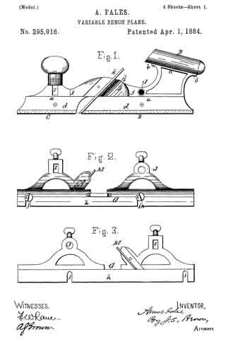
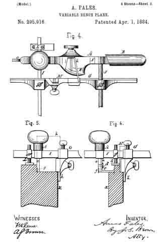
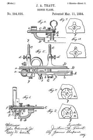
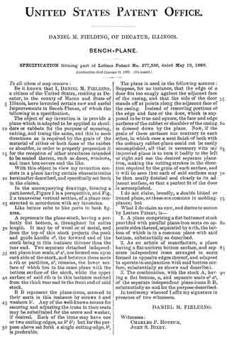
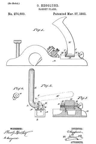
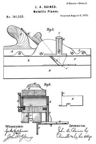
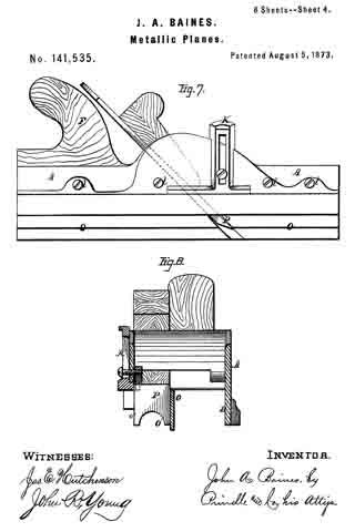
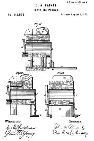
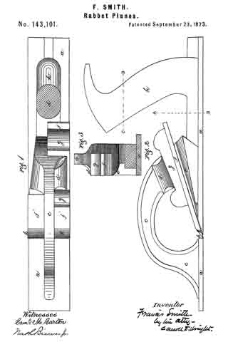
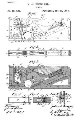
In the accompanying sheet of drawings, Figure 1 is a side view of a plane comprising the present invention. Fig. 2 is a plan view of same. Fig. 3 is a central vertical section of the plane on line 3 3 of Fig. 2. Fig. 4 is a horizontal sectional view in detail on line 4 4, Fig. 3. Fig. 5 is a plan view of a portion of the face of the plane. Fig. 6 is a section on line 6 6, Fig. 3.

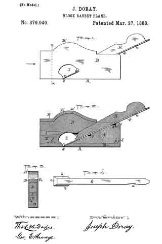
In the drawings, A represents the plane body or stock, having plates B at each side thereof, covering the whole area thereof, except at the portion a, at and over the plane-throat C.

D is a throat-plate adapted to be movable, as hereinafter explained, and E is the plane-iron, having cutting-edge b, as usual in planes.

F is the plane-iron holder, which has a transverse rib, d, corresponding and closely fitting a transverse groove, f, in the plane-iron. The upper end of the plane-iron holder is provided with a right-angled lug or ear, g, through the inner screw-thread of which a screw-threaded bolt, F2, engages. This bolt F2 has a head, h, which lies in a recess, K, at the rear of a lug, Z, in the casting, and the shank of the screw-bolt F2 plays loosely through a hole, m, therefor in said lug l. The head of the bolt F2 is milled, and at each side projects through apertures K in the side plates, B, of the plane-stock,and may be conveniently turned by the hand to project or withdraw the edge of the plane-iron at the throat, as is plain.

G is a block which bears on the upper side of the plane-iron, and it has a tongue, p, projecting upwardly in the inner recess of the plane-stock, through which is a slot, q, having a direction perpendicular to the plane-iron E, through which slot is passed a stationary pin, r, extending from side to side of the plane-stock. Above the stationary pin r, and bearing on and between it and the upper wall of the slot q, is a spiral spring, s, which tends to force the block G upwardly away from the plane-iron. Resting over and upon the edge of block G is a cam-disk, J, pivotally hung in the plane-stock, as at j, having a handle-arm, J2, and all so arranged that when said arm is swung downwardly, as shown, it will of itself so remain until swung upwardly from the plane-iron E, allowing same, through the turning of the screw-bolt, to be altered in its projection, or to be removed, as desired.

The throat-plate D has its outer face of the same width as the face of the plane-stock, and it has a tongue or upward projection, K2, extending into the open space w, formed in the stock A. Extending through the part v of the stock is a screw-threaded bolt, L, which engages the female screw-threads of the upward extension K2 of the throat-plate D, and the end of the screw-bolt L is supported in a socket, w2, in the part x of the stock, as seen in Fig. 3, said bolt being prevented from longitudinal movement in one direction by the end of socket w2, and in the other direction by its abutment against the plate M, secured on the end of the plane-stock. The plate M, however, has a hole, w3, of diameter smaller than that of the bolt L, opposite such head, through which a screwdriver or wrench may be inserted to engage with the screw-slot. By turning the screw-bolt in one direction the throat-plate is moved toward the plane-iron to contract the opening or throat C, and when turned in the other direction the throat-opening is thus widened.

M2 M2 are pointed blades or groovers which are located at opposite sides of the plane in longitudinal lines coincident with the outer edges or corners of the plane-iron, as shown in plan view, Fig. 5, in advance of the plane iron. These blades are adapted and intended to be projected a distance beyond the face of the plane as great at least as the projection beyond the face of the plane of the plane-iron, and in the operation ofthe plane, in the usual manner, the blades M2 M2 form parallel grooves or demarkations, exactly within and between which the cutting plane-iron E follows and cuts the shaving.

The grooving-blades M’ M” extend through dovetailed grooves a2 in the throat-plate, and are beveled or dovetailed on their edges, fitting the dovetailed grooves in the throat-plate. There is also a clamp, N, for receiving each grooving-blade, having inner dovetailed grooves, d2, corresponding to the dovetail shape of the blades M2. The clamps N2 are adapted to be drawn inwardly, carrying the blades M2 therewith in a transverse line of the plane and firmly against the stock at its portion a3 above and below the clamp N, and inwardly against the inner wall, a4, of the grooves in the throat~plate, and this inward bind of the grooving-blades is secured by the screw-pin O, differentially threaded at its opposite end portions z, having intermediate of its length a squared portion, z2, by which a permanent or other wrench-arm, P, engages, the turning of which screw-pin in one direction causes the clamps N to move inwardly, and the turning of the screw-pin in the opposite direction causing the clamps to move outwardly for maintaining the bind of the blades M2 against the side of the stock and throat-plate, or for releasing such bind to permit the adjustment or release of the grooving-blades.

The opposed sides of the stock A. are provided with horizontal ways or grooves d3, in which play projections d4 of the clamp N, permitting the clamps to move longitudinally of the plane-stock, as the blades are so carried when the throaaplate D is moved longitudinally either to widen or contract the throat.

Having thus described my invention, what I claim, and desire to secure by Letters Patent, is —

1. The combination, with the plane-stock having the pin r, the cam J, and the plane-iron, of the block G between said cam and plane-iron, having slot q, substantially as described.

2. The combination, with the plane-stock having the pin r, the cam J, and the plane-iron, of the block G between said cam and plane-iron, having slot q, and spring s, substantially as and for the purpose described.

3. The combination, with the recessed plane-stock having lug m, screw F2, ribbed plane-holder F, having lug g, notched plane-iron E, and pivoted cam J, having handle J2, of block G between said cam and plane-iron, having slot q, and spring s, substantially as and for the purpose described.

4. The combination, with a plane-stock having vertically-arranged recesses a3 a3, and the horizontal grooves d3 d3, of the clamping-blocks N N, having dovetailed sockets, inwardly-extending projections d4, and threaded screw-receiving holes, the right and left threaded screw having the intermediate projecting lever, P, and grooving-knives having dovetailed edges bearing in said socketed block, substantially as described, for the purposes set forth.

In testimony that I claim the foregoing as my invention I have signed my name in presence of two witnesses.

JULIUS ARMIN BISSEGGER.

Witnesses:
WM. SEARS BELLOWS,
CHAS. S. SENTELL.

No. 379,940 – Block-Rabbet Plane (Joseph Doray) (1888)

[paiddownloads id=”432″]379940


UNITED STATES PATENT OFFICE.

_________________

JOSEPH DORAY, OF WORCESTER, MASSACHUSETTS.

BLOCK-RABBET PLANE.

_________________

SPECIFICATION forming part of Letters Patent No. 379,940, dated March 27, 1888.
Application filed August 15, 1887. Serial No. 247,032. (No model.)

_________________

To all whom it may concern:

Be it known that I, JOSEPH DORAY, of the city and county of Worcester, and Commonwealth of Massachusetts, have invented a new and useful Block-Rabbet; and I do hereby-declare that the following is a full description of the same, reference being had to the accompanying drawings, and the letters of reference marked thereon, forming a part of this specification, and in which —

Figure 1 represents a side view of my said block-rabbet ready for use. Fig. 2 represents a longitudinal vertical central section of the device and the parts of which it is composed, except the knife or cutter, which is not shown in section. Fig. 3 represents a cross-section on line x x, Fig. 1, looking in the direction indicated by the arrow, Fig. 1; and Fig. 4 represents a top or plan view of the knife or cutter detached, as will be hereinafter more fully described and explained.

To enable those skilled in the art to which my invention belongs to make and use the same, l will now describe the invention more in detail.

In the drawings, A represents the complete device ready for use. The part marked B represents the metal shell or case, and is made in a peculiar manner. The right-hand end of the device is made with an opening to permit the right-hand end of the part C to project out flush with the outer surface of the end of the shell B, while the shoulders j and k of the part C rest or abut against the shoulders h and i of the shell B, all as fully shown in Fig. 2. The upper left-hand end of the filling-piece C is made with an inclined or wedge-shaped surface to receive and support the rear part of the cutting end of the knife and its shank end, as fully indicated in the drawings.

The wooden filling-piece D is made inclined up or wedge-shaped on its under side (right-hand end) to iit against and hold the wedge or holding-piece H, while its upper edge (right-hand end) is made in curved form, as shown at D’, to fit the inner upper curved part, B’, of the shell B. The under surface of the left-hand end is inclined up or in wedge shape as it extends back from the middle of said piece. The wooden filling-piece E is made, in this instance, with a notch, f to fit over the projection e on the inner surface of the bottom of the left-hand end of the shell B, while the upper surface of the filling-piece E is inclined down or in wedge shape from its inner to its outer end.

Between the left-hand ends of the wooden filling-pieces C and D is inserted wedge-piece F.

For the convenience of the constructor or user in putting the part C in place, a notch, g, is made in the upper inclined edge of the part C to receive the end of a forcing stick. In the proper and best use of the tool the slot or slit d should extend from side to side, so that the cutting end c will be as wide as the shell or case is thick, and to enable the operator to insert the cutter or knife G, the space between the parts C and D is great enough to let the knife run down when turned up edgewise at an angle of about thirty degrees until it reaches the opening I, in which it can be turned down into place and fastened by the holding-wedge H. By this mode of construction the opening or slit d can be made quite narrow, just wide enough to let the edge of the knife through and allow the passage of a very thin shaving.

By making the knife or cutter G thin and flat, as shown, excepting the parts provided with the bevels b b and c, the device is rendered light, while at the same time, where it is clamped by the holding-wedge H, being flat and thin, it readily yields to the pressure of said wedge and conforms to the surfaces between which it is clamped, and is thus clamped and securely held in position. Then, again, by making the lower end thick and providing it with bevels b b on its sides a cutting-edge, c, can be obtained, which, when the cutter is in position, as shown in Figs. 1 and 2, will cut the full width of the metal shell or case, and which cutting end is held firmly to its work by the end of the holding-wedge H bearing and wedging thereon, as also shown in Figs. 1 and 2 of the drawings, while by the notch a the cutter can be drawn back and adjusted after the holding-wedge H has been loosened. It will thus be seen that the outer thin flat end of the cutter will readily bend or yield, and will be caught, clamped, and firmly held at some point back of the point where the lower end of the holding-wedge rests upon the lower thin flat end of the cutter, and that, too, without any undue straining of the parts.
The piece of wood filling C is first run into place, then the wood filling-piece D is inserted, then the piece E, and then the wedge-piece F is driven in, thereby fastening the parts C, D, E, and F securely in position in the shell or case B, which, as before stated, is made of metal. In practice I prefer to apply glue to the sides and edges of the wedge-holding piece F before it is driven in, thereby rendering the parts D, E, and F as firm as if made of a single piece. A single piece, it will be noticed, could not be inserted.

If preferred in any case, the wedge F may be dispensed with, also the notch f and projection e, and the piece E made to wedge with the piece D, and if glued before being driven in will be fastened to the part D, the curved projection D’ preventing the parts from moving either forward or back. I prefer, however, to make the parts as shown inthe drawings.

The shell or case B, it will be noticed, is made and adapted for this tool, and the same is true of the knife or cutter, neither of which is suitable for usein any other tool. By my mode of construction the tool can be made very cheap, and so strong are all the parts united that one will last a man’s life-time.

Those skilled in the art will readily understand and appreciate the great practical value and utility of my said invention. The tool can be made small, even small enough to be carried in the pocket, and thus be ever at hand for use. This tool takes the place of a chisel in finishing the corners of rabbets, repairing beadings, and like work, while the work can be done much quicker and more perfectly than in the ordinary manner, and when the great amount of this work required in finishing good articles and buildings is considered the saving in time and expense by the use of my said invention, even in the hands of a single work man, is large.

Having described my newly-invented block-rabbet, what I claim as my invention, and desire to secure by Letters Patent, is —

1. The combination, with the metal shell or case B, of the wood filling or parts C, D, and E, knife G, and holding-wedge H, as shown and described, and for the purposes set forth.

2. The combination, with shell or case B, provided with the projection e, of the wooden filling-piece E, having the notch j, to receive the projection e, as and for the purposes set forth.

3. The combination, with the metal shell or case B, made as described, of the wooden filling pieces C, D, and E and wooden wedge-piece F, substantially as shown and described, and for the purposes set forth.

4. The knife or cutter G for a block-rabbet, having a thin flat end with a notch, a, and a thick cutting end with top beveled edges b b and c, as described and shown, and for the purposes stated.

5. A metal shell or case, B, for a block-rabbet, provided with lips or shoulders h and i, projection e, opening I, and narrow slit d, all as shown and described, and for the purposes stated.

JOSEPH DORAY.

Witnesses:
THOS. H. DODGE,
GEO. E. SAVAGE.

No. 351,689 – Rabbet-Plane (William Henry Buswell) (1886)

[paiddownloads id=”416″]351689


UNITED STATES PATENT OFFICE.

_________________

WILLIAM HENRY BUSWELL, OF MANSON, IOWA.

RABBET-PLANE.

_________________

SPECIFICATION forming part of Letters Patent No. 351,689, dated October 26, 1886.
Application filed May 6, 1886. Serial No. 201,351. (No model.)

_________________

To all whom it may concern:

Be it known that I, WILLIAM HENRY BUSWELL, a citizen of the United States, residing at Manson, in the county of Calhoun and State of Iowa, have invented certain new and useful Improvements in Rabbet-Planes; and I do declare the following to be a full, clear, and exact description of the invention, such as will enable others skilled in the art to which it appertains to make and use the same, reference being had to the accompanying drawings, and to letters or figures of reference marked thereon, which form a part of this specification.

Figure 1 of the drawings is a representation of this invention, and is a top view. Fig. 2 is an end view. Fig. 3 is a detail, and is a vertical section through one of the cast-metal plates.

My invention relates to rabbet-planes designed for use in making rabbets of any desired depth and width in the material to be worked, without previously having to gage the rabbet or use a bevel-square; and the invention consists in the construction and novel combination of parts, as hereinafter described, and pointed out in the claim.

Referring by letter to the accompanying drawings, A designates the stock of the plane, which is provided with the bit-iron B, held in the stock by the wedge C, and the stock may be with or without a handle, according to the kind of plane-stock used. At its ends the stock A of the plane is provided with the cast-metal plates D and E, which plates are provided with longitudinal parallel slots F G, near their upper and lower edges, said slots extending nearly from end to end of said plates, the plates being beveled on their rear faces along the edges of the slots to form elongated countersinks, in which fit the heads H on the screw-stems I.

J J’ are rectangular plates secured to the enter faces of the slotted plates D E, said plates J J ‘ being held to their adjustments on the outer faces of the slotted plates D E by the screws I and thumb-nuts K K’.

L L’ are pivoted plates, secured to the rectangular sliding plates J J ’ by pivots M, passed through their lower inner corners. The pivoted plates L L’ are provided with arc slots N, in their cam-shape portions O, and from these cam-shape portions O project integral arms P, between which the gage-bar Q is secured by screws R R’, passed through holes in the arms P into the ends of the gage-bar Q.

By loosening the thumb-nuts K K’ the gage-bar can be moved in or out as far as the parallel slots will permit the slotted rectangular plates to slide.

By loosening the thumb nuts V V’ on the screws Y Y’, passed through the arc slots N, the gage-bar Q may be turned on its pivots, and be thereby caused to assume the required angle, after which the thumb-nuts V V’ may be tightened to hold the gage-bar at the angles to which it has been adjusted while the plane is being used. The upper edge of the gage-bar is beveled to fit the bottom of the plane and hold the gage-bar at the proper angle when said edge is moved under the stock of the plane.

Having described this invention, what I claim, and desire to secure by Letters Patent, is–

The improved rabbet-plane described, consisting of the stock A, the plates D E, having ing the parallel longitudinal slots and secured to the opposite ends of the stock in a plane relatively at right angles to the face thereof, the sliding rectangular plates J, held in sliding engagement with the said end plates by the transverse screws and nuts I K, the gage-bar, the plates R, having a semicircular slot, the thumb-nut working therein, an arm, P, for attachment to the ends of the said gage-bar, and their lower inner portions pivoted to a like point of the sliding end plates, substantially as specified.

In testimony whereof I affix my signature in presence of two witnesses.

WILLIAM HENRY BUSWELL.

Witnesses:
A. L. FUNK,
SOLOMON M. HEATH.

No. 309,400 – Joiner’s Plane (George D. Mosher) (1884)

[paiddownloads id=”379″]309400


UNITED STATES PATENT OFFICE.

_________________

GEORGE D. MOSHER, OF BIRMINGHAM, CONNECTICUT.

JOINER’S PLANE.

_________________

SPECIFICATION forming part of Letters Patent No. 309,400, dated December 16, 1884.
Application filed November 3, 1884. (No model.)

_________________

To all whom it may concern:

Be it known that l, GEORGE D. MOSHER, of Birmingham, in the county ot’ New Haven and State of Connecticut, have invented a new lmprovement in Joiners’ Planes; and l do hereby declare the following, when taken in connection with accompanying drawings and the letters of reference marked thereon, to be a full, clear, and exact description of the same, and which said drawings constitute part of this specification, and represent, in —

Figure 1, a left-hand side view; Fig. 2, a right-hand side view; Fig. 3, a longitudinal central section; Fig. 4, a transverse section on line x x of Fig. 1; Fig. 5, a transverse section on line z z of Fig. 1.

This invention relates to an improvement in that class of joiners’ planes which consist of a cast-metal stock fitted with a clamping device to hold the cutter, and mechanism for adjusting the cutter with relation to the mouth, the object of the invention being to simplify the construction, so that the plane may be produced with very little mechanical labor, and thereby greatly reduce the cost; and the invention consists in the construction, as hereinafter described, and more particularly recited in the claims.

A represents the base or plate of the stock, fitted at one end with a handle, B, and may be at the other with a handle, C, and with the usual transverse mouth, a, opening into the throat D. Imrnediately in rear of the throat is a bearing, E, inclined to the position required for the cutter, and upon which the lower end of the cutter F may lie. Centrally from this bearing E a lug, b, extends upward, inclined corresponding to the incline of the bearing-surface E.

G is the bed for the cutter. At its lower end it is constructed with a recess, d, upon its face side, corresponding, substantially, to the lug b, as seen in Figs. 3 and 5. The face of the cutter-bed G forms, substantially, a continuation of the inclined bearing E, as seen in Fig. 3. The upper end of the bed G is constructed with a groove upon its under side, to ride upon a guide, c, formed on the handle portion above the bearing-surface E. The groove is best formed by a rib or flange near each edge of the upper part of the bed, to embrace the bearing e, as seen in Fig. 4. The bed is constructed with a hook, f, upon each side near its lower end, these hooks formed by extending or turning the edge upward and inward, as seen in Fig. 5.

H is the cap for the cutter, provided at its upper end with a set-screw, I. The hooks are of such extent that the cutter F may be set down between them and the bed, and then the cap H introduced between the cutter and the hooks, as seen in Figs. 3 and 5, the cap extending down toward the edge of the cutter, the screw taking its bearing upon the cutter above the hooks. Thus introduced, the screw is turned to a bearing upon the cutter, forcing the cutter firmly against the bed G, and causing the lower end of the cap to turn inward against the cutter and clamp the cutter upon the bearing E, as seen in Fig. 3, so as to firmly secure the cutter in its place. The cap may be adjusted to any desired relation to the edge of the cutter, so that it may serve as the cap for the cutter to govern the depth of the cut, if desired.

To adjust the cutter the bed G is constructed with a flange, h, upon one side of the handie portion, as seen in Figs.1 and 4. This flange is constructed with a notch or opening, i. Through the handle portion a coarse-threaded screw, L, is introduced, the handle portion being correspondingly screw-threaded, as seen in Fig. 4. This screw is provided with an eccentric stud, Z, which stands in the slot ffl of the bed, and so that if the screw be turned to iinpart a cranlrdilre nrovenient to the stud l, it will correspondingly move the bed G up or down, according to the rotation of the screw E. Upon the reverse side the screw is provided with a handle, M, by which it may be conveniently turned. The screw-thread on this adjusting device imparts a longitudinal movement to the stud l as the screw is turned, hence produces a transverse friction between it and the surface of the notch i in which it works, in addition to the friction which naturally arises from the rotative bearing of the stud. Such transverse friction adds materially to the hold which the stud takes upon the bed, so that accidental displacement is not liable to occur, as would be the case were the screw E constructed with simply a cylindrical surface in the stock, and so that rotative movement only would be imparted to the adjusting-stud l. By this construction the stock is readily molded and cast complete, the cleaning and preparation of the casting to receive the cutter and bed being an inconsiderable operation. The bed G is also cast complete, ready for application to the stock without any material mechanical labor, and thus I produce a plane at a minimum cost, yet complete and perfect in its working and adjustment.

To prevent the possibility of the cutter being thrown out of adjustment by contact with knots, or other extraordinary hard attacks in operation, I construct the face of the bed with a series of notches on its face, and provide the cutter with a corresponding stud, in, (see Fig. 3,) and so that when the cutter is set in place the stud may enter one of the notches in the bed and there hold firmly, so that any adjustment of the bed must be necessarily irnparted to the cutter, and the notch and stud serve to resist any tendency of the work to throw the cutter out of adjustment.

I claim —

1. The metal stock, constructed with the inclined bearing E in rear of its mouth, and with the lug b extending upward and backward therefrom, the bed G, constructed with a recess, d, upon its face, corresponding to the said lug D, said bed also constructed with hooks f f, and arranged to take a bearing on the stock above the said lug, combined with the cutter F, cap H, and the set-screw I in said cap, substantially as described.

2. The metal stock, constructed with an inclined bearing, E, in rear of its mouth, and with a lug, b, extending upward and backward therefrom, the bed G, constructed with a recess, d, corresponding to said lug, and arranged to take a bearing on the stock above, and also constructed with hooks f f, and with a downwardly-projecting flange having a notch, i, therein, the cutter F, cap H, and set-screw I, with the screw E transversely through the stock, said screw provided with an eccentric stud, l, at one end to work in said notch i, the opposite end provided with a handle, M, substantially as and for the purpose described.

3. The stock constructed with the inclined bearing E in rear of its mouth, and with the lug b extending upward and backward therefrom, the bed G, constructed with a recess, d, corresponding to said lug, and also with hooks f f, the said bed arranged to take a bearing upon the stock above the said lug b, the face of the said bed constructed with a series of notches, the cutter constructed with a stud, m, upon its under side to engage either of said notches, the cap H, and set-screw I, substantially as described.

GEORGE D. MOSHER.

Witnesses:
THOS. L. I. BULLUSS,
WM. H. WILLIAMS.

No. 308,332 – Rabbet-Plane (Justus A. Traut) (1884)

[paiddownloads id=”378″]308332


UNITED STATES PATENT OFFICE.

_________________

JUSTUS A. TRAUT, OF NEW BRITAIN, CONNECTICUT, ASSIGNOR TO
THE STANLEY RULE AND LEVEL COMPANY, OF SAME PLACE.

RABBET-PLANE.

_________________

SPECIFICATION forming part of Letters Patent No. 308,332, dated November 18, 1884.
Application filed May 17, 1884. (No model.)

_________________

To all whom it may concern:

Be it known that I, JUSTUS A. TRAUT, a citizen of the United States, residing at New Britain, in the county of Hartford and State of Connecticut, have invented certain new and useful Improvements in Rabbet-Planes, of which the following is a specification.

My invention relates to improvements in rabbet-planes, and has for its object a better arrangement for the gages.

In the accompanying drawings, Figure 1 is a side elevation of my rabbet-plane. Fig. 2 is a like view of the reverse side of the same. Fig. 3 is an end view of the same. Fig. 4 is a sectional view of a portion of the stock on line x x of Fig. 2, said view also showing the gage-rod in side elevation 5 and Fig. 5 is a horizontal section of the depth-gage and a portion of the stock with a side elevation of the clamping-screw.

The stock A may be of any ordinary form; but as shown it is provided with two bit-seats, into either of which the cutting bit a may be secured. This feature of the stock, however, was known prior to my present invention. The bit a at the cutting end is the full width of the stock.

b is the gage-rod, upon which the socket of the gage B is fitted, so that the gage may be adjusted longitudinally upon said rod and fastened in place by means of the set-screw c, thereby securing the working-face of the gage B at any desired point with reference to the under surface of the stock. As shown in the drawings, this gage is adjusted for use in working from the left-hand edge of a board. The gage-rod b is secured to the stock by means of its threaded end and a correspondingly-threaded hole in the side of the stock. In order to facilitate the screwing out and in of this rod, I provide its end with an orifice into which a suitable pin or wrench may be applied. Upon the opposite side of the stock, and in alignment with the hole into which the gage-rod is secured, I form a like threaded hole, f, Figs. 1 and 4.

When it is desired to convert the tool to one for gaging from the right-hand edge of a board, the gage-rod b is unscrewed from one side of the stock, and then inserted in hole f, and the gage B then secured thereon, as indicated by broken lines in Fig. 3. By making the gage-rod attachable and detachable to and from either side of the stock the rods never project upon that side which is opposite the gage B, thereby enabling the gage and plane to be used in corners and cramped places where it is impossible to use a rabbet plane and gage whose gage-rods project upon said side.

C designates the depth-gage, the shank of which is slotted for insertion of the clamping-screw g, which passes through the shank of the depth-gage and into a threaded hole in the stock. The side of the stock to which this gage is secured is provided with a vertical V-shaped groove, h, Figs. 1 and 5, which groove is a little to one side of the clamping-screw g. The inner face of the gage C is provided upon one side of the clamping-screw with a V-shaped rib, k, and upon the opposite side of the screw is a plain-faced rib, l, Fig. 5. The V-shaped rib governs the position of the gage in its movement up and down, while the plane-faced rib, in connection with the V-shaped rib, forms a seat or bearing-surface to hold the gage at a proper distance from the side of the stock. This construction enables the gage to be governed in its vertical position, and to form a proper bearing-surface, only a small portion of which requires to be fitted, and consequently it can be fitted with but little labor and expense.

Any suitable spur or spurs may be attached to the side or sides of the stock just forward of the cutting-bit, as in prior rabbet-planes.

I am aware that depth-gages of various kinds have been heretofore employed upon rabbet-planes having side gages; also, that prior patents show rabbet-planes having side gages with two rods permanently secured thereto, and having transverse holes through the stock into which said gage-rods were inserted and held therein by means of set-screws, whereby the gage could be changed end for end, and placed upon either side of the stock to convert the tool into a right or left hand plane, as required. All of said prior art is hereby disclaimed.

I claim as my invention —

1. The herein-described rabbet-plane, consisting of the stock A, having screw-holes f upon opposite sides and in alignment with each other, the gage-rod b, screw-threaded upon its end to fit both of said holes in the stock, and the reversible gage B, having the set-screw c, and a socket for securing the rod b, all substantially as described, and for the purpose specified.

2. In a rabbet-plane, the combination of the stock A, having the groove h, the depth-gage C, having a central slot with the rib k fitted to rest upon the bottom of the groove h at one side of said slot, and the plane-faced rib l, which abuts against a plane surface on the stock at the opposite ends of said slot, the clamping-screw g, the gage-rod b, and the side gage, B, all substantially as described, and for the purpose specified.

JUSTUS A. TRAUT.

Witnesses:
H. S. WALTER,
HENRY C. HINE.

No. 305,602 – Bench-Plane (John A. Keiser) (1884)

[paiddownloads id=”371″]305602


UNITED STATES PATENT OFFICE.

_________________

JOHN A. KEISER, OF CINCINNATI, OHIO.

BENCH-PLANE.

_________________

SPECIFICATION forming part of Letters Patent No. 305,602, dated September 23, 1884.
Application filed June 30, 1884. (No model.)

_________________

To all whom it may concern:

Be it known that I, JOHN A. KEISER, a citizen of the United States, and a resident of Cincinnati, in the county of Hamilton and State of Ohio, have invented certain new and useful Improvements in Bench-Planes, of which the following is a specification.

This invention relates to improvements in benoh-planes; and it has for its object to provide novel and efficient means for adjustably connecting the cutter with the plane-stock. This I accomplish in the manner and by the construction and combination of devices hereinafter described and claimed, reference being had to the accompanying drawings, illustrating my invention, in which —

Figure 1 is a side elevation of my improvement. Fig. 2 is a cross-section on line x x, Fig. 1. Fig. 3 is a perspective view of the side gage. Fig. 4 is an enlarged detail view of the side gage and fastening-clamp. Fig. 5 is a detail view of the clamping device.

A represents the base of my plane-stock; B, the side of the stock, G, the handle; c, the ledge on which cutter a rests and is secured.

D represents the cutter-clamp, which is operated as follows:

E represents a bell-crank lever, which is pivoted at e and the side of the stock B.

b represents the arm of bell-crank lever, to which the clamp D is pivotally attached.

b’ represents a shoulder or stop for limiting the pivotal movement of clamp D on arm b, to force the points d down upon the cutter a.

The crank E is made to have two bearing-points, d d. The clamp D is raised and lowered by the movement of the bell-crank lever E. When occupying the position shown in Fig. 1, the clamp D is forced down upon the cutter a, and holds it securely in position. When it is desired to readjust the cutter a, or to take it out, the bell-crank E is lifted up, which moves the points of the clamp away from contact with the cutter a, and allows it to be removed or adjusted.

F represents a mortise or opening pierced through the side of the stock B.

G represents the adjustable side gage, which is provided with a mortise, g, through which is inserted a clamp, and a slot, h, which slides over the shank of the clamp, for allowing the gage G to be adjusted.

H represents a headed clamp-bolt.

I represents the shank of the same, over which the slot h of the gage G moves up or down for its adjustment.

K represents a cam or eccentric lever pivoted to the shank I, which, when turned up, bears against the face of the gage G, securely clamping it in position by drawing the head of clamp-bolt H against the side of the plane-stock, and the cam clamping or pressing against the outside of the gage G. When the lever K is turned down, gage G is released, so that it may be adjusted to the desired height. The mortise g is sufficiently large to allow the eccentric-lever K to pass through the opening g, for the engagement of the slot h, upon the shank I of the clamp-bolt. This device may be readily adjusted and attached to, or removed from the plane. By this method of constructing the side gage the metal of the plane-stock is but slightly weakened, and a very convenient detachable gage is obtained.

I Claim —

In combination with the plane A B, having the ledge c, and the bell-crank E, pivoted to the side of the plane and pivotally connected to the cutter-clamp D, said bell-crank being provided with stop b’, substantially as described.

In testimony whereof I have hereunto set my hand.

JOHN A. KEISER.

Witnesses:
A. GLUCHOWSKY,
A. E. SCOTT.

No. 299,927 – Plane (Samuel E. Hilles) (1884)

[paiddownloads id=”366″]299927


UNITED STATES PATENT OFFICE.

_________________

SAMUEL E. HILLES, OF CINCINNATI, OHIO.

PLANE.

_________________

SPECIFICATION forming part of Letters Patent No. 299,927, dated June 3, 1884.
Application filed March 19, 1884. (No model.)

_________________

To all whom it may concern:

Be it known that I, SAMUEL E. HILLES, a citizen of the United States, and a resident of Cincinnati, in the county of Hamilton and State of Ohio, have invented certain new and useful Improvements in Planes, of which the following is a specification.

My invention relates to an improvement in planes.

The object of my invention is, first, to provide suitable attachments for holding the cutter or bit in position; second, to provide improved means for attaching both vertical and side guides to regulate the cutting of grooves, gains, or rabbets.

The invention consists in the novel construction and combination of devices hereinafter described and claimed, reference being had to the accompanying drawings, in which —

Figure 1 is a perspective view of my invention, with the attachments in position for use. Fig. 2 is a central vertical section on line x x, Fig. 1. Fig. 3 is a detail view of the vertical guide; Fig. 4, a perspective view of the side guide; Fig. 5, a detail view of one of the attachments of the side guide.

A B represent an L-shaped plane-stock; C, a handle, the parts being preferably cast in one piece.

a represents a flange upon which the cutter b rests. It is desirable in a plane to provide means for quickly and easily securing the cutter in position, and which can be readily inserted or removed, dispensing with the set-screw, and using instead thereof a cam or eccentric, which bears upon the wide face of the bit or cutter, and holds it more firmly in position than a set-screw, and which can be also more readily set or detached, being more durable than when the cap is secured by screw-threads, which must be formed in the plane-stock, or in the cap, so that common grey iron cannot be practically employed for that purpose.

E represents my improved cap, provided with a lug, e, extending transversely across its upper face, and which engages with the groove formed in the under face of boss D, said groove and lug being arranged across or substantially at right angles to the line of travel of the tool, so that the cap is thereby prevented from longitudinal movement. This lug e and the groove in the face of boss D are rounded or V-shaped, so as to prevent the cap E from being driven downward as the cam-lever F is turned down. A rectangular gain and lug would cause the parts to bind, and not allow the cap E to be raised vertically if the parts are fitted so as to prevent longitudinal motion. The cap E is inserted and removed laterally.

F represents a cam-lever fulcrumed upon the cap E, the face of the cam being as wide as the cutter b, and which when turned down upon the cutter, as shown in Fig. 1, securely holds it in its position on the bed or flange a. The cutter can be loosened, and it, with the cap, quickly removed by turning up the cam F.

G represents a gage or fence, which is secured to the side plate, B, in the following manner:

c represents a vertical groove cut in the face of the side B.

d represents a lug cast on the inner face of the guide G, which engages with the groove c and prevents lateral movement of the guide.

h, represents a slot, pierced through the shank of guide G, through which passes the shank of set-screw H, which taps into the side stock B of the plane, and holds the gage in position. This construction allows the gage G to be adjusted up and down, and secures its adjustment upon the side of stock B without weakening the stock, and in this respect it is an improvement upon the device shown and described in Letters Patent No. 284,941, granted J. M. Bennett, September 11, 1883. The guide G maybe readily removed when it is desired to use the plane with the side B resting against the wood, as in planing into a corner. It is also desirable to provide a side gage, which may be readily attached to or removed from its position on the stock of the plane, and which can be secured thereto in such a manner as not to weaken the stock, which is preferably made of common grey iron. For this purpose I provide a boss, I, on the top face of stock A.

J represents a gage-stock, which is provided with a gain, K, on one of its edges, which gain is of the same width as the side gage, M, so as to allow it to be retracted outward a sufficient distance to employ the full width of the cutter b.

l represents lugs formed upon one side of the gage-stock J, which rests upon the top surface of the stock A, and prevents it from rocking.

L represents a thumb-screw, which is inserted through the gage-stock J, and taps into the boss I, rigidly securing stock J in position to firmly hold the gage M.

n represents a transverse gain cut upon the under surface of the gage-stock J. It is made of the proper shape to receive the slotted shank N, which slides laterally in the gain n, for adjusting the gage M to any desired width of cut.

O represents a set-screw for attaching the gage M to the gage-stock J in such a manner as to adjust the gage, as before described. It will be seen that the gage-stock J and the gage M can be readily attached to or removed from the plane-stock by means of the attaching screw L.

I claim —

1. The combination, in a plane, of the right-angled stock A B, having the flange a, and attached lateral boss D, constructed with a longitudinal groove on its under side, the cap E, having a lug, e, extending transversely across its upper face, and adapted to be slipped sidewise into engagement with the groove of the boss to prevent movement of the cap in the direction of its length, and the swinging cam F, pivoted to the upper end of the cap, for clamping the cutter b upon the flange a substantiallty as described.

2. The combination, with the plane-stock A B, formed with a groove, c, in one side of the part B, but not extending through it, of the adjustable gage G, slotted vertically and provided with the lug d and the set-screw H passed through the slot of the gage and tapped into the part B of the stock, substantially as described.

3. The combination, With the right-angled stock A B, having the boss I on the top face of the part A, of the gage-stock J, provided with lugs l, resting on the face of stock A, and the thumb-nut L inserted through the stock J, and tapped into the boss I to secure stock J in position, substantially as described.

4. The combination of the right-angled stock A B, provided with the boss I on the face of the part A, the gage-stock J, provided with lugs l resting on the face of stock A and , formed with the transverse gain n, and secured to the stock by screw L, the gage M, formed with slotted shank N, entering gain n, and screw O for attaching gage M to stock J substantially as described.

In testimony whereof I have hereunto set my hand.

SAML. E. HILLES.

Witnesses:
ANDREW E. SCOTT,
A. GLUCHOWSKY.

No. 296,207 – Joiner’s Plane (George D. Mosher And William H. Ford) (1884)

[paiddownloads id=”362″]296207


UNITED STATES PATENT OFFICE.

_________________

GEORGE D. MOSHER AND WILLIAM H. FORD, OF BIRMINGHAM, CONN.

JOINER’S PLANE.

_________________

SPECIFICATION forming part of Letters Patent No. 296,207, dated April 1, 1884.
Application filed January 21, 1884. (No model.)

_________________

To all whom it may concern:

Be it known that we, GEORGE D. MOSHER and WILLIAM H. FORD, of Birmingham, in the county of New Haven and State of Connecticut, have invented a new Improvement in Joiners’ Planes; and ive do hereby declare the followiing, when taken in connection with accompanying drawings and the letters of reference marked thereon, to be a full, clear, and exact description of the same, and which said drawings constitute part of this specification, and represent, in —

Figure 1, a left-hand side view; Fig. 2, a right-hand side view, Fig. 3, a face view; Fig. 4, a sectional side view, to illustrate the adjustment of the cutter, Fig. 5, a section on line x x, looking downward, to show the connection between the cutter and the hub of the adjusting-lever.

This invention relates to an improvement in planes for joiners’ use, particularly to that class in which the stock is constructed from cast metal.

The principal object of the invention is to construct the stock with the mouth and throat extending entirely across it, and whereby the possibility of “choking” is avoided; but it also has for its object a simple and easy adjustment of the cutter; and the invention consists in the construction, as hereinafter fully described, and more particularly recited in the claims.

A represents the rear portion, and B the front-portion, between which the mouth a is formed. This mouth extends entirely across the face of the plane, as seen in Fig. 3, instead of leaving a connection between the front and rear portions at each end of the mouth, as in the usual construction. As the front and rear parts of the stock are separated by this mouth, We connect them above and over the throat C by a connection, D, extending from the handle E at the rear to a handle, F, at the front. This connection is made in the form of a thin web centrally on the stock, so as to make the plane as light as it conveniently can be. The back of the throat is inclined to form a seat, b, for the cutter d in the usual relation to the mouth. From the seat b a standing screw-threaded stud, e, extends forward at right angles to the seat, over which the cutter will set, the cutter being constructed with a slot for such purpose, and so as to permit the cutter to be moved up or down, as occasion may require. The cutter placed thereon, a cap or clamping piece, f, is applied over the bolt, and then a nut, h, turned thereon, clamps the cutter to its seat. This stud e is best fixed in place by being introduced into the mold and the metal cast around it.

As a simple and convenient means for adjusting the cutter, we arrange a lever, i, upon a hub, l, which extends through the web, and so as to take a seat therein and permit the hub to be turned by applying the fingers to the lever. The handle stands upon one side of the web, as seen in Fig. 5.

On the cutter, above the stud e, is a stud, m. From this stud a link, o, extends up to the hub l on the opposite side to the lever i, and is there connected to the hub by an eccentric pin or screw, p, as seen in Fig. 5. Therefore by turning the lever i the eccentric pin p imparts a corresponding movement to the link, and thence to the cutter, so that turning in one direction the cutter may be drawn upward, or in the opposite direction forced downward, according to the adjustment required.

By this construction of plane the throat and mouth are open from side to side, so that the cuttings or shavings must readily pass out of the throat, and cannot by any possibility be stopped therein, so as to choke the mouth. The adjustment of the cutter is simple and cheap.

We are aware that metal planes have been constructed with the mouth extending from side to side in like manner as in what are known as “rabbet-planes,” and therefore do not claim, broadly, such a plane.

We claim —

1. A cast-metal plane having the front and rear portions separated by the mouth and throat, whereby said mouth and throat are open from side to side, the front and rear portions connected over the throat, the rear portion constructed vvith a seat, b, for the cutter, said seat provided with a fixed screw-threaded stud, e, the cutter d, the clamp f, and nut h, substantially as described.

2. A cast-metal plane having the throat and mouth open from side to side, the rear and front portions of the stock connected centrally centric connection with the hub of said lever, over the throat above the cutter, the rear portion constructed with a, seat to receive and support the cutter, the adjusting-lever i, arranged above the cutter in the connection which unites the rear and front portions, and a link in connection with the cutter and in eccentric connection with the hub of said lever, substantially as described.

GEORGE D. MOSHER.
WILLIAM H. FORD.

Witnesses:
EDWIN B. GAGER,
ANDREW J. EWEN.

No. 295,916 – Variable Bench-Plane (Amos Fales) (1884)

[paiddownloads id=”361″]295916


UNITED STATES PATENT OFFICE.

_________________

AMOS FALES, OF DENVER, COLORADO.

VARIABLE BENCH-PLANE.

_________________

SPECIFICATION forming part of Letters Patent No. 295,916, dated April 1, 1884.
Application filed March 31, 1883. (Model.)

_________________

To all whom it may concern:

Be it known that I, AMOS FALES, of Denver, in the county of Arapahoe and State of Colorado, have invented certain Improvements in Variable Bench-Planes; and I do hereby declare that the following is a full and exact description thereof, reference being had to the accompanying drawings, making part of this specification.

These improvements are upon variable bench-planes constructed upon the general plan set forth in Letters Patent granted to me March 7, 1882, No. 254,542, and are mainly additional thereto, although I have in one or two respects changed and improved the construction therein shown and described. Except as to these changes, as hereinafter specified, I use the invention substantially as described in the said Letters Patent; but it is to be understood that the improvements herein described and claimed may be applicable to other constructions of bench-planes besides those therein set forth; and my invention is intended to embrace all applications to which the several features, any or all, may be adapted.

In the accompanying drawings, Figure 1 represents a front side view of the main stock of the bench-plane and parts belonging thereto, constructed with my present improvements, Fig. 2, a front side view of the auxiliary stock and attached parts constructed with my present improvements 5 Fig. 3, a back side view of the said auxiliary stock; Fig. 4, a top view of the two stocks connected together for use; Fig. 5, a front view of the stocks arranged as in Fig. 4; Fig. 6, a front view of the two stocks arranged for tonguing; Fig. 7, a front view of the stocks arranged for grooving; Fig. 8, a similar view of the stocks arranged to constitute a front fillister; Fig. 9, a similar view of the stocks arranged for a back fillister; Figs. 10, 11, and 12, views showing the construction of the auxiliary stock adapted to other kinds of work.

Like letters designate corresponding parts in all the figures.

First, in the construction of the main stock A, I employ an improved handle, as represented in Figs. 1 and 4. The handle proper, B, is turned in simple cylindrical form, with one side slightly flattened to rest upon a straight plane-surfaced flange, a, cast upon the stock. Screws b b attach the handle to the flange, which is suitably inclined to give the handle the proper position for grasping. Not only is this construction of the handle very simple and cheap, but it is very easy for the hand and convenient for use in connection with other parts of the instrument, not interfering with the adjustment of the cutters; also, the molds or form-plates C D, instead of having shoulders to fit under the lower edge of the stock-flange c, for holding them in proper position, I now form their vertical attaching-flanges d d each with upward extensions e e, to bear against the shoulder formed by the projecting lower edge of the body f of the stock. This construction of the form-plates leaves the lower edge of the stock-flange c free and unobstructed and enables me to permanently attach thereto one dado-spur, g, as shown in Figs. 4 to 9 of the drawings, and saves the expense of two spurs on each dado. and it is always in position for use.

Another change in the construction of the main stock consists in terminating the lower part of the cutter-bracket E at the line of the shoulder or lower edge of the body f of the stock, thereby leaving the stock without side projections beyond the stock-flange below the said line, so that very narrow grooves may be out to the full depth of the said flange.

Second, in the construction of the auxiliary stock G, I form the stock and cutter-holder in one instead of two parts or sections, thus simplifying and cheapening the construction and rendering the use ofthe stock more convenient, and enabling me to apply any other attachment which may be desired. The stock thus approximates in construction and use to the main stock.

Further, for many purposes the fiange h of the auxiliary stock extends lower than or entirely below the corresponding flange, c, of the main stock, as shown in Fig. 5 and following figures of the drawings. This enables me to use, if desired, a cutter in the main stock, which may extend laterally over the auxiliary stock, as shown, for instance, in Fig. 5. Besides, it enables me to employ, in connection with the auxiliary stock, a “fence” or gage and guide-strip, H, for uses such as illustrated in Figs. 7, 8, and 9, and hereinafter set forth. This fence is preferably made of wood, and is consequently cheap and light. It is made of the form shown or any other most convenient. It is attached to the flange h of the auxiliary stock below the body thereof, which forms a guide-shoulder, by two screws, i i passing through notches j j of the stock-flange, so that it is easily attached and detached. Its surface, which faces the main stock, is plane and parallel therewith. By adjusting the auxiliary stock to the required distance from the main stock on the connecting-bars I J this fence may be brought to bear against and run along one side of the stuff to be worked, and serve as a guide for the instrument and gage for the work.

In Figs. 4 and 5 and the following figures of the drawings I illustrate the operation of the instrument provided with the above-de-
scribed improvements.

In Figs. 4 and 5 is shown an arrangement for a front fillister, with a wide cutter, k, in the main stock overlapping the auxiliary stock, which in this case needs no cutter, but is low enough in the middle to allow the lapping over of the main-stock cutter. The flange h furnishes the side gage, and the vertical gage-stop L is mounted on the connecting-bar I, back of the main stock, to gage the depth of the cut in the board or stuff x, indicated by dotted lines in Fig. 5.

In Fig. 6 is shown an arrangement for tonguing. Here also the flange h of the auxiliary stock serves as the side gage, and the vertical gage-stop is mounted between the two stocks. The cutter k of the main stock cuts behind the tongue of the board x, and a cutter, M, in the auxiliary stock cuts in front of the tongue.

In Fig. 7 I show an arrangement for grooving. In this arrangement a fence, H, is used on the auxiliary stock for the side gage, and the vertical gage-stop I is arranged back of the main stock, the cutter k of the main stock cutting the grooves in the board or plank x, in connection with the fixed dado-spur g on the main-stock flange.

In Fig. 8 is shown an arrangement for a front fillister, with the use of a fence, H, on the auxiliary stock. By this arrangement as narrow a rabbet or shoulder may be cut in the stuff as ever will be required.

In Fig. 9 is shown an arrangernent for a back fillister, a fence, H, on the auxiliary stock furnishing the side gage, and the vertical gage-stop L being mounted between the two stocks.

Figs. 10, 11, and 12 show a construction of the auxiliary stock adapted to kinds of work in which it is not convenient for the flange h to project lower than the main stock — as, for instance, in making window-sashes. Here the stock-flange h projects horizontally, and the fence H is attached below it, the attaching-screws i i going down through notches j j, which allow a lateral adjustment of the fence.

As seen in Fig. 12, the screws i i enter the fence nearer one edge than the other. When the fence is attached, as shown, the fence is back of the front side of the stock, allowing the cutter M of the stock to cut over the sash x or other article. By reversing the position of the fence, however, the edge of the same projects in front of the stock, as required for some kinds of work. There is a notch or depression, l, Figs. 10 and 11, in the middle of the auxiliary stock, to allow the center of the main stock to reach over the auxiliary stock, when desired. The auxiliary stock is depressed under this notch, the fence being cut away to allow the two to come together.

I claim as my invention —

1. In a bench-plane, a handle, B, made of cylindrical form, flattened on one side, in combination with an inclined plane-faced flange, a, on the plane-stock. substantially as and for the purpose herein specified.

2. The combination of the main stock A, having the lower edge of its body f and cutter-bracket E in one straight line, and its flange c provided with a dado-spur, g, and the form-plates C D, having vertical attaching-flanges d d bearing against the straight lower edge of the said stock-body and bracket, and adapted to have their lower surfaces flush with the lower edge of the said stock-flange, substantially as and for the purpose herein specified.

3. The reversible fence H, in combination with the stock G, the points of attachment being to one side of the middle longitudinal line of the fence, whereby two positions are given thereto fulfilling two purposes, substantially as herein specified.

4. The combination of the main stock A, having a downwardly-extended flange, c, on its lower edge, and a cutter extending laterally beyond the stock, and the auxiliary stock G, cut away at the top to allow the main-stock cutter to project over it, and having a flange, h, bent laterally, substantially as and for the purpose herein specified.

In testimony whereof I have signed my name in presence of two witnesses.

AMOS FALES.

Witnesses:
J. DEWEESE,
H. T. CASTLE.

No. 295,316 – Rabbet-Plane Attachment (Charles A. Warfield) (1884)

[paiddownloads id=”359″]295316


UNITED STATES PATENT OFFICE.

_________________

CHARLES A. WARFIELD, OF PHILADELPHIA, PENNSYLVANIA.

RABBET-PLANE ATTACHMENT.

_________________

SPECIFICATION forming part of Letters Patent No. 295,316, dated March 18, 1884.
Application filed September 18, 1883. (No model.)

_________________

To all whom it may concern:

Be it known that I, CHARLES A. WARFIELD, a citizen of the United States, residing at the city of Philadelphia, in the county of Philadelphia and State of Pennsylvania, have invented certain new and useful Improvements in Rabbet-Plane Attachments; and I do hereby declare the folioiving to be a full, clear, and exact description of the invention, reference being had to the accompanying drawings, which form part of this specification, in which —

Fignre 1 is a perspective of a plane with my attachment applied thereto. Fig. 2 is an end view, same parts as Fig. 1. Fig. 3 is a perspective of attachment.

My invention has for its object to provide a gage or regulating attachment for a rabbet-plane, whereby the width or depth of at rabbet cut may be controlled without employing a marker or equivalent device. My attachrnent consists of a bar provided with means for attaching it adjustably to the face of a common plane or rabbet-plane, forming a guide or gage therefor, substantially as hereinafter fully set forth.

Referring to the accompanying drawings, A represents a common rabbet-plane, to which my attachment is applied. B represents the attachment, consisting of a bar, preferably of metal, with lugs or flanges b b’ at either end. One of these lugs is serrated, as shown at b2, on its inner side, while the other lug has a screw or equivalent lever, or other securing appliance, by which it is made fast to the plane. When the screw C is turned in, it draws the log b’ against the opposite end of the plane, and so holds the attachment firmly on the latter. One side of the attachment constitutes a straight-edge, b3. The other side may be curved or of any desired configuration.

The attachment is adjusted on the face of the plane, with the straight-edge b3 at the same distance from the edge a of the plane as will equal the depth or width of the rabbet required to be cut. The plane is then ready for use. To cut rabbets of different widths or depths, the attachment must be correspondingly adjusted, such adjustment being very readily effected.

As will be seen, the attachment requires no change to be made in the stock of an ordinary plane, and when removed permits the use of the latter in its ordinary manner.

To prevent the bit d of the plane from coming in contact with the attachment, the latter should have a transverse groove, as shown at b5.

I am aware that it is not new, broadly, to provide a plane with an adjustable guide or gage for the purpose of cutting shelved or channeled sufaces; but such as I have any knowledge of have required a special adaptation of the plane to the purposes of the guide. I therefore do not broadly claim an adjustable rabbeting attachment, but limit myself to a guide of such a construction that it may be applied to any ordinary plane by simply clamping the attachment in place.

What I claim as my invention is —

The rabbet attachment for planes herein described, consisting of bar B, having its upper or inner surface flat and transversely grooved, and provided with lugs b b’ and a screw, C, or equivalent means for securing said attachment to the plane, substantially as shown and set forth.

In testimony that I claim the foregoing I have hereunto set my hand this 7th day of September, 1883.

CHARLES A. WARFIELD.

Witnesses:
LISLE STOKES,
WILL H. POWELL.

No. 294,825 – Bench-Plane (Justus A. Traut) (1884)

[paiddownloads id=”358″]294825


UNITED STATES PATENT OFFICE.

_________________

JUSTUS A. TRAUT, OF NEW BRITAIN, CONNECTICUT.

BENCH-PLANE.

_________________

SPECIFICATION forming part of Letters Patent No. 294,825, dated March 11, 1884.
Application filed October 17, 1883. (No model.)

_________________

To all whom it may concern:

Be it known that I, JUSTUS A. TRAUT, a citizen of the United States, residing at New Britain, in the county of Hartford and State of Connecticut, have invented certain new and useful Improvements in Bench-Planes, of which the following is a specification.

My invention relates to improvements in bench-planes. In my improved plane I combine a beading and center-beading tool, plow, dado, fillister and rabbet, matching-tool, and slitting-tool.

The objects of my improvement are to render the combined tool simple in construction and convenient to change from one form to another, and to improve its working in many particulars when changed. I attain these objects by the construction illustrated in the accompanying drawings, in which —

Figure 1 is a side elevation of my tool arranged for use as a plow. Fig. 2 is a plan view thereof. Fig. 2A is a vertical section of detached parts on line z z of Fig. 2. Fig. 3 is a side elevation, showing the reverse side of said plow as compared with Fig. 1. Fig. 4 is a vertical section of the same on line x x of Fig. 1. Fig. 5 is a reverse plan view of my plane arranged for use as a matching-tool. Fig. 6 is a vertical section thereof on line y y of Fig. 5. Fig. 7 is a side elevation of a detached portion of the stock, showing the adjustable spur. Fig. 8 is a like view of the same as set in a different position, so as to throw the spur out of action; and Figs. 9 and 10 are like views of a modified form of the same.

My convertible or combination tool consists of three principal parts — viz., the two parts of the stock and the gage or fence. These parts are found in a prior patent to myself, dated March 4, 1873, and the changes herein described in those parts may be considered in the nature of an improvement upon the plane shown in said patent.

I make the parts A and B of the double stock mainly of cast metal, and with thin steel blades on at secured thereto. These I prefer to let into a rabbet upon the inner faces of the parts A B, and with a dovetailed or overhanging upper surface for said rabbet, the upper edges of the blades being correspondingly formed, as shown in Figs. 4 and 6. I secure these blades to the parts A B by means of screws or rivets b. The lower edges of these blades, upon their inside corners, may be beveled off, as shown, in order to adapt the blades for use in connection with a beading-cutter. By thus making the blades or lower edges of the stock of steel, the stock may be made much lighter than a cast-iron stock, while at the same time it is stronger. I am also enabled to make said blades rnuch narrower, and thereby I adapt the device for use with a much narrower cutter than has heretofore been practical. In fact, they may be made so thin as to adapt the tool for use with a cutter only one-
eighth of an inch in width.

As in prior implements of this class, the part A of the stock is provided with gage or fence rods C, for connecting and adjusting the two parts of the stock, and also for adjusting and holding the gage or fence D in proper position relatively to the stock. Instead, however, of providing this fence with only one set of holes for the rods C, I provide two sets of holes or sockets, c, and I arrange the fastening-screw d’ intermediate between said two holes or sockets, as shown most clearly in Figs. 1 and 2A, and I slightly bevel the end of the set-screw d’, so that it will impinge upon the rod C and hold the same, whether it bein the upper or lower one of the sockets c. This construction of the fence enables it to be placed higher up on the stock for certain uses, as shown in Figs. 1, 3, and 4, or so as to come lower down relatively to the bottom of the stock, as shown in Fig. 6.

I have herein illustrated the cutters d e as held in place by means of the clamp-bolt f as shown and described in my prior patent, before referred to; but any other ordinary clamping mechanism may be substituted therefor.

Upon the outside vertical faces of the blades a a, at any suitable point thereon, but preferably a little in front of the throat, as shown in Fig. 3, I arrange spurs g, for use in connection with a plow or dado, the uses of such spurs being well known. I place these spurs in a circular depression so located with reference to the edge of the stock that it runs out at the lower edge. The spur proper is formed as a radial arm of a thin steel hub or disk, having a pivotal screw, h, passed through its center into the center of the circular recess in the sides of the blades a a. I prefer to form upon this rotary spur three other arms, as shown, two of which act in connection with a stationary stop, i. By loosening the screw h, the spur may be thrown so as to project directly downward from the bottom of the stock, in which position it is stopped by contact of one of the arms with the stop i, as shown in Figs. 3 and 7, in which position it may be held by tightening the screw h. The stop, however, in connection with the pivotal screw h, is in such position as to receive the thrust or working-strain which comes upon the spur g in driving the tool forward, so that it is only necessary to tighten the screw h suffiiciently to prevent the spur from working out of place when the plane is drawn backward. When it is desired to throw the spur wholly out of action, it is only necessary to loosen the screw and turn the spur forward until another one of the arms strikes the stop i, as shown in Fig. 8, when the screw may be tightened sufficiently to hold the rotatory spur in said position. If desired, all four of the arms on this spur-disk may be sharpened, so that by loosening the screw far enough to let the arms slip by the stop, either of said arms may be brought downward so as to proiect below the lower edge of a, whereby a sharp and fresh cutting-spur can he brought into action in case the one first set in position for action by any means becomes impaired.

In Figs. 9 and 10 I have shown a modification of the spur-disk, and the manner of holding it in the stock. Instead of the circular recess before described, I sink a star-shaped depression or recess in the side of the stock, the lower part of which recess, as in the former case, extends to the lower edge of the stock. The spur-disk is substantially the same as before, except that I either make one short arm or make only three arms to radiate from the hub. I employ the same central fastening-screw; but instead of the stop i being formed separately in the form of a pin, and subsequently secured to the stock, the eccentric shape of the edge of the recess enables the walls thereof to perform the function of a stop to prevent the spur from rotating in either direction.

In order to set the spur g’ in position tor action, it is placed so as to extend downward and project below the bottom face of the stock, as shown in Fig. 9; or in case all of the arms are sharpened, the spur-disk may be set with either of its arms extended downward, as may be desired. In order to throw the spur out of action, it is only necessary to loosen the screw enough to let the spur-disk come forward out of the recess — that is, out of engagement with its stop — and then partially revolve on the central screw, so as to bring the short arm or side having no arm toward the bottom face of the stock, and then drop the spur-disk into its recess and tighten the screw, as shown in Fig. 10. In like manner the spur-disk may be changed to bring either arm of the spur into action.

E, Figs. 2, 3, and 5, designates a depth-gage of ordinary construction, and consequently a description is unnecessary.

F designates a slitting-knife vertically adjustable within a suitable seat upon the part A of the stock, for use in connection with a plow-stock substantially as shown and described in the patent to Rappleye, No. 266,519, October 24, 1882. In connection with this slitting-knife I employ another depth-gage, G, Figs. 3 and 5, and fasten the same in place by the same screw and nut which secure the slitting-knife F. I have shown the depth-gage E as placed in the main part A of the stock, (said part being that which carries the handle and rods C C;) but I provide the sliding part B of the stock with a socket, k, and set-screw m, as shown in Fig. 2, to receive and hold said gage when desired.

Having described the general construction of the parts, I will now describe the manner of using my improved plane tor the several purposes hereinbefore named. For all of these various uses, except in using the plow with a very narrow cutter, both parts of the stock are used together, and it is not necessary that any of the parts hereinbefore described shall remain detached for using my plane as any of the foregoing-named tools, except the dado, and for beading in the middle of a wide surface.

In order to use my plane as a beading and center-beading tool, I insert and fasten the proper-shaped cutter, bringing the two parts of the stock together, and placing the depth-gage in the part A of the stock, the fence or gage D being preferably set with the rod C in the lowest sockets, so as to bring the gage at the highest point, as shown in Fig. 4. If the bead is to be formed at a distance from the edge of the board greater than that to which the gage may be adjusted, said gage will have to be removed and a suitable strip fastened upon the board to gage by, the same as with other beading-tools. For beading crosswise with the grain, the spurs g should be thrown into cutting action.

For use as a plow, a cutter is selected of a desirable width and clamped in place, the two parts of the stock brought together, the depth-gage properly adiusted, the fence D being secured as shown in Fig. 4, and the spurs g brought into position for acting. By placing the gage for the plow higher up with reference to the bottom of the stock, instead of lower down, as shown in Fig. 6, it can be made to gage the work much more properly, and to steady the plow against tipping over sidewise, because it will bear against the edge of the surface of the work to its extreme upper edge, even after the cutters have plowed to a considerable depth , whereas with a gage set low down, as shown in Fig. 6, that portion of the edge surface of the work which is above the lower end of the cutter is also above the top edge of the gage, so that said portion of the surface can furnish no support whatever against the tool tipping over sidewise. The broken lines in Fig. 4 indicate a piece of work that has been plowed a distance about equal to half the depth of the gage D, and shows the relative position of the gage and stock thereto.
If a cutter is to be used whose width is less than that of the combined thickness of the blades a a, the removable part B of said stock and its blades a must be removed. The remaining part A may then be used with a cutter of practically the same width as the thickness of the blade a.

For a dado, the fence or gage D is wholly removed, a suitable cutter is inserted in place, and the two parts of the stock brought together, the depth-gage E is secured and properly adjusted within the sliding part B of the stock, and the spurs g set for cutting action.

For a fillister and rabbet, a cutter of the desired width is selected and properly secured within the stock, the depth-gage is placed in the part A of the stock, and the fence or gage D secured by passing the rods C through the upper sockets of said gage, as shown in Fig. 6.

For a slitting-tool, the knife F is properly adjusted and the tool used in the manner set forth in the patent to Rappleye hereinbefore specified. The bottom gage, G, may also be used in connection therewith, if desired. This gage may also be brought down into position for use when the slitting-knife is drawn upward or removed, if desired, and while the other depth-gage, E, is placed in the sliding part D of the stock, thereby bringing a depth-gage into action upon both sides of the stock, for use in connection with any of the several tools.

The cutter d (shown in Figs. l, 2, and 3) is an ordinary cutting-bit with an edge square across the end.

The cutter e (shown in Figs. 5 and 6) is one which is specially adapted for a matching-tool, and is provided with a depth-gage, a, secured directly to the cutter. This cutter is shown herein merely to show my plane as adapted for a matching-tool, and said cutter and its gage I intend to make the subject of another application of even date herewith.

In lieu of the gage n, other gages may be arranged to bear upon the edge of the tongue for gaging the depth.

I employ a matching-tool having a narrow shank with a wider bit at its cutting end, so that when its narrow shank is set in position and the two parts of the stock brought against the respective edges thereof the cutting-edge of the bit will project laterally upon both sides of the stock, at the bottom part thereof, as shown in Figs. 5 and 6.

The gage or fence D is placed in its lowermost position, so that it may slide under the cutting-edge of the cutter and bottom edge of the stock, as shown in Fig. 6. This enables me to adjust the gage to a point from the middle of the cutter a distance equal to half the thickness of the board to be tongued, and when so adjusted the tongue formed on the board by this matching-tool will always be exactly in the middle, and this can be accomplished with the use of only one cutter in any board whose thickness is not greater than the width of the cutter at its lower end, and which is not so narrow as the space between the blades a a, or, in other words, the longitudinal groove in the bottom face of the stock. By thus making the cutting end of the cutter wider than the span of the blades a a or working-face of the stock, I can with a single cutter centrally tongue boards of different thicknesses within the limits before named.

I claim as my invention —

l. The combination of the gage-rods C C of a bench-plane, the gage or fence D, having two sets of sockets-one above the other-and suitable means for fastening said gage upon said rods, substantially as described, and for the purpose specified.

2. The combination of gage-rods C C, a suitable gage or fence having double sockets for the reception of said rods, and a set-screw arranged intermediately between the sockets and adapted to clamp the rods when placed in either one of the sockets, substantially as described, and for the purpose specified.

3. The combination of the stock and the rotatory cutting-spur adapted to project below the edge of the stock, or to be carried up above said edge by turning it upon its axis, substantially as described, and for the purpose specified.

4. The combination of the stock, the rotatory spur pivoted thereto, and a suitable stop for limiting the rotation of said spur during the forward movement of the stock, substantially as described, and for the purpose specified.

5. The combination of the stock, the spur-disk having radial arms, the adjusting-screw, by means of which said disk is secured to the stock, and a suitable stop for preventing said spur-disk from rotating on said screw, substantially as described, and for the purpose specified.

JUSTUS A. TRAUT.

Witnesses:
JAMES SHEPARD,
JOHN EDWARDS, Jr.

No. 284,941 – Rabbet-Plane (John M. Bennett) (1883)

[paiddownloads id=”341″]284941


UNITED STATES PATENT OFFICE.

_________________

JOHN M. BENNETT, OF GREEN ISLAND, NEW YORK, ASSIGNOR TO
HENRY C. BAILEY, OF COVINGTON, KENTUCKY.

RABBET-PLANE.

_________________

SPECIFICATION forming part of Letters Patent No. 284,941, dated September 11, 1883.
Application filed August 18, 1882. (No model.)

_________________

To all whom it may concern:

Be it known that I, JOHN M. BENNETT, a citizen of the United States, residing at the village of Green Island, in the county of Albany and State of New York, have invented new and useful Improvements in Rabbet-Planes, of which the following is a specification.

My invention relates to improvements in rabbet-planes; and the objects of my improvements are to provide a strong and durable stock and base or bed-piece of suitable metal, having a cutter adjusted by means of a cap and screw, and also a guide or fence, so that it can be used with either hand and as a fillister. I attain these objects by the mechanism illustrated in the accompanying drawings, in which —

Figure 1 is a view in perspective of the plane complete. Fig. 2 is a view in perspective of the guide or fence. Fig. 3 is a view in perspective of the cap.

Similar letters refer to similar parts throughout the several views.

The stock L extends along the right side of the base or bed-piece A and at a right angle thereto, and has a suitable handle, O, at the rear end thereof. At a suitable point in the base or bed-piece A a throat is cut through and entirely across said base or bed-piece, into which throat the cutting-edge of the cutter B is placed and worked. Running from the rear side of the throat upward, upon a proper angle toward the rear of the stock, and cast thereon or fastened thereto, is the cutter-rest M, which is straight and flat, and upon which the cutter rests.

The cap C is a littler shorter than the cutter-rest M, and at the end placed near the throat is of the same width as thecutter, and is flat upon the under side and beveled to an edge upon the upper side. The under side of the cap C is flat and slightly concave to a point from the lower end for about two-thirds its length, from which point it is straight and inclined slightly upward. The upper side of said cap C is irregular in form, being the highest and narrowest at the point where the slot K is cut, and slightly convex from thence to the lower end and concave to the upper end. It is obvious, however, that any other form from the beveled end upward that will give a bearing at the slot K and lower end, and by means of the screw J at the upper end properly hold the cutter B in its position, may be used. Passing through the upper end of the cap C is a screw, J — a thumb-screw being the most convenient — the lower end of which is in contact with the upper side of the cutter B, and by means of which the pressure of the cap upon the cutter is regulated and the cutter held firmly in position or removed. At the highest point of the cap C, and upon the upper side thereof, is out crosswise a slot, K, to admit therein the lug or brace D, by means of which the cap is prevented from moving lengthwise. The lug or brace D is cast upon or fastened to the inside of the stock L, at a point about midway the throat and the upper end of the cutter-rest M, and projects over and a little beyond the center of said cutter-rest. Its size and shape are such as to be adapted to the use to which it is to be put. Through the stock L, at the front side of the throat, is cut a perpendicular slot, G, of any required width and length.

The guide E is a flat smooth piece, of suitable material and size, having firmly attached an upright, with a shoulder, F, made to fit and work in the slot G, and thus keep the base-piece of the guide always parallel to the base or bed-piece A. This guide is placed upon the outside of the stock K, and firmly fastened thereto by means of a screw, N, which passes through the slot G and into a suitable opening, having a corresponding thread cut therein, in the said upright. This guide may be raised or lowered at pleasure, and thus regulate the depth of the cut of the plane. A suitable opening is made through the stock L, extending a short distance upward from the throat in a line with the cutter, to allow the cuttings of the cutter to pass away from the throat, and this opening, as well as the throat, should be of such size and shape as are best adapted to a free and easy discharge of the cuttings of the cutter.

The cutter may be of much the same kind as those in ordinary use in planes. The lower or cutting end is of the same width as the face of the base or bed-piece A, and continues that width the length of the opening aforesaid in the stock L, and is from thence of about the same width as the cutter-rest M.

The handle O is of proper size and shape to fit the hand, and may be east as a part of and with the stock. Thus the base or bed-piece A, the stock L, handle O, lug or brace D, and cutter-rest M may all be cast of iron or other suitable metal, at one time and in one piece, forming a tool that will not warp or wear and work to a sharp corner. The size, of course, may be such as is required.

I am aware that prior to my invention rabbet-planes have been made. I therefore do not claim such plane, broadly; but

What I do claim as my invention, and desire to secure by Letters Patent, is —

In a plane, the stock L, having the slot G made through it, in combination with the guide E, provided with the flange F, and the set-screw H, for holding the guide in position, substantially as shown.

JOHN M. BENNETT.

Witnesses:
JNO. H. O’BRIAN,
PETER H. BUCKLEY.

No. 277,556 – Bench-Plane (Daniel M. Fielding) (1883)

[paiddownloads id=”334″]277556


UNITED STATES PATENT OFFICE.

_________________

DANIEL M. FIELDING, OF DECATUR, ILLINOIS.

BENCH-PLANE.

_________________

SPECIFICATION forming part of Letters Patent No. 277,556, dated May 15, 1883.
Application filed January 31, 1883. (No model.)

_________________

To all whom it may concern:

Be it known that I, DANIEL M. FIELDING, a citizen of the United States, residing at Decatur, in the county of Macon and State of Illinois, have invented certain new and useful Improvements in Bench-Planes, of which the following is a specification.

The object of my invention is to provide a plane which is adapted to be applied to shoulders or rabbets for the purpose of squaring, cutting, and truing the same, and this in such directions as is required by the grain of the material of either or both faces of the rabbet or shoulder, in order to properly proportion it for the reception of other structures intended to be seated therein, such as doors, windows, and inset box-covers and the like.

With this object in view my invention consists in a plane having certain characteristics hereinafter described, and specifically set forth in the claims.

In the accompanying drawings, forming a part hereof, Figure 1 is a perspective, and Fig. 2 a transverse vertical section, of a plane constructed in accordance with my invention.

Like letters refer to like parts in both figures.

A represents the plane-stock, having a perfectly flat bottom, a, throughout its entire length. It may be of wood or of metal, and from the top of this stock projects the push and guide handle a2, the forward end of the stock being in this instance thinner than the rear end. Two separate detached independent plane-iron seats, a3 a4, are formed one upon each side of the stock, and between these seats a rib or partition, a5, remains, the lower surface of which lies in the same plane with the bottom surface of the stock, while the upper surface of said rib is in this instance inclined from the thick rear end to the front end of said stock.

B B represent the plane-irons, secured in their seats in this instance by screws b and washers b1. Any of the well-known means for securing and adjusting the irons in their seats may be substituted for the screw and washer, if desired. Each of the irons may have one or two cutting-edges, as b2 b3; but forthe purpose above set forth a single cutting-edge, b2, is preferable.

The plane is used in the following manner: Suppose, for an instance, that the edge of a door fits too snugly against the adjacent face of the casing, and that the side of the door stands od at points along the adjacent face of the casing. Instead of removing portions of the edge and face of the door, which is supposed to be true and square, the face and edge surfaces of the rabbet or shoulder of the casing is dressed down by the plane. Now, if the grain of these surfaces run contrary to each other, in which case a neat finish of both with the ordinary rabbet-plane could not be easily accomplished, all that is necessary with my improved plane is to turn it bodily to the left or right and use the desired separate plane-iron, making the cutting-strokes in the direction required by the grain of each surface, and it will be seen that each of said surfaces may be then neatly finished and closely to its adjacent surface, so that a perfect fit of the door is accomplished.

I do not claim, broadly, a double bitted or ironed plane, as these are common in molding-planes; but

What I do claim as new, and desire to secure by Letters Patent, is —

1. A plane comprising a flat-bottomed stock provided with parallel plane-iron seats on opposite sides thereof, separated by a rib, the bottom of which is in a common plane with said bottom, substantially as described.

2. As an article of manufacture, a plane having a flat uniform bottom surface, and separate independent irons arranged in seats formed in opposite edges thereof, and adapted to operate in conjunction with said bottom surface, substantially as shown and described.

3. The combination, with the stock A, having a flat bottom, a, and separate seats a3 a4, of the separate independent plane-irons B B, substantially as and for the purpose described.

In testimony whereof I affix my signature in presence of two witnesses.

DANIEL M. FIELDING.

Witnesses:
CHARLES P. HOUSUM,
JOHN S. BIXBY.

No. 274,600 – Rabbet-Plane (Oliver Hegglund) (1883)

[paiddownloads id=”331″]274600


UNITED STATES PATENT OFFICE.

_________________

OLIVER HEGGLUND, OF OAKLAND, NEBRASKA.

RABBET-PLANE.

_________________

SPECIFICATION forming part of Letters Patent No. 274,600, dated March 27, 1883.
Application filed December 5, 1882. (No model.)

_________________

To all whom it may concern:

Be it known that I, OLIVER. HEGGLAND, of Oakland, in the county of Burt and State of Nebraska, have invented a new and useful Improvement in Rabbet-Planes, of which the following is a full, clear, and exact description.

This invention consists of a contrivance of the handle of a rabbet-plane for adjusting it into several different positions with relation to the plane, to adapt the plane for holding in different ways for different kinds of work, as hereinafter described.

Reference is to he had to the accompanying drawings, forming a part of this specification, in which similar letters of reference indicate corresponding parts in all the figures.

Figure 1 is a side elevation of a rabbet-plane with a handle applied according to my invention. Fig. 2 is an end elevation. Fig. 3 is a section of figures on line x x; and Fig. 4 is a perspective view of the nut employed, together with the binding-screw for securing the handle.

A represents the plane-stock, on the back end of which I attach the block B by screws a, so that it can be readily detached, said block having a recess, C, between ears D, wherein I pivot the handle E, as shown, on the binding-screw F, on which screw the handle can turn when not screwed up tight by the screw, the said screw being fitted in the ears D, and traversing the recess C, on which the handle is located, and screwing into a nut, H, in one of the ears in which said nut is fitted so as not to turn, so that it can draw up against the handle and bind it fast against the other ear.

K is a set-screw screwing into the recess from the back of the block and binding against the nut of the handle to secure it in any position in which it may be set. The handle is constructed with the bend L, for the purpose of enabling it to he turned over the back of the block B, as shown by the dotted lines in Fig. 2. The block B is detachably connected to the plane-stock, as before stated, for the purpose of detaching it and attaching a long straight handle projecting rearward of the plane-stock, and in line with it, when the plane is to be used for dressing deep mortises.

Having thus described my invention, I claim as new and desire to secure by Letters Patent —

1. In a rabbet or other plane, the combination, with the recessed block or support secured upon the rear end of the stock, of the pivoted handle having the bend L, the pivotal screw, and the holding or adjusting screw, substantially as and for the purpose set forth.

2. In a rabbet or other plane, the combination, with the recessed block or support secured upon the rear end of the stock, of the handle having its hub arranged in the recess of said block, against which hub bears a holding or set screw, the pivotal screw, and binding-nut, fitted to slide in one of the ears of the block and to bear against one end of the handle-hub, and adapted to be operated by the pivotal screw, substantially as and for the purpose set forth.

OLIVER HEGGLUND.

Witnesses:
JOHN GEDROW,
WALTER HEGGLUND.

No. 269,967 – Bench-Plane (Jacob Siegley) (1883)

[paiddownloads id=”325″]269967


UNITED STATES PATENT OFFICE.

_________________

JACOB SIEGLEY, OF NEW YORK, N. Y.

BENCH-PLANE.

_________________

SPECIFICATION forming part of Letters Patent No. 269,967, dated January 2, 1883.
Application filed May 22, 1882. (No model.)

_________________

To all whom it may concern:

Be it known that I, JACOB SIEGLEY, of the city, county, and State of New York, have invented certain new and useful Improvements in Planes, of which the following is a specification.

This invention has reference to improvements in that class of planes known as shoulder-planes, which are also used as block and rabbet planes; and it consists of means whereby the cutting-tool is rigidly clamped to the stock of the plane, and adapted to be readily adjusted after clamping, as will be more fully described hereinafter.

In the accompanying drawings, Figure 1 represents a vertical longitudinal section of my improved plane. Fig. 2 is a plan view of the same. Figs. 3 and 4 are a detail bottom view and a vertical transverse section on line x x, Fig. 3, of the cutting-tool employed; and Fig. 5 is a vertical transverse section of the plane on line y y, Fig. 2.

Similar letters of reference indicate corresponding parts.

In the drawings, A represents the stock of my improved shoulder-plane, which stock is made of cast metal, and provided with a flat bottom having vertical side shoulders. A’. The side shoulders, as well as the bottom, are arranged with recesses tor the inclined cutting-tool B, the narrower upper part of which is provided with a slot, b, while the lower part has three cutting-edges, b’, one at the lower end and one at each side, as customary in shoulder-planes. The slotted upper part of the cutting-tool B is clamped to interior cheeks, a1 a2, of the bottom part of the stock A by means of a tongue, C, and a clamping-screw, d, that passes through a slot, d’, of the tongue C and the slot b of the cutting-tool B, as shown clearly in Fig. 1. At the upper end of the tongue C is arranged a second clamping-screw, d2, whereby the pressure of the tongue C upon the cutting-tool B may be increased or decreased in the usual manner. The under side of the upper | part of the cutting-tool B is provided above the slot b with transverse grooves or serrations e, which are engaged by a worm-screw, e’, of a spindle, D, that is supported in inclined position parallel to the cutting-tool B, in suitable bearings of the cheeks a1 a2, the spindle being extended in upward direction, and provided with a milled or other head, D’, for taking conveniently hold of the spindle D. By turning the spindle in one or the other direction the cutting-tool B is adjusted higher or lower in the stock, as required for the stock.

By means of the adjusting mechanism described the cutting-tool in the plane can be accurately adjusted without loss of time, so that the use of the plane as a shoulder-plane or block or rabbet plane is considerably facilitated.

Having thus described my invention, I claim as new and desire to secure by Letters Patent —

1. In a shoulder-plane, the combination of a stock, A, having side shoulders, A’, and raised bottom cheeks, a1 a2, with a cutting-tool, B, a clamping-tongue, C, and means whereby the cutting-tool is adjusted in the stock, substantially as set forth.

2. The combination of a stock, A, having side shoulders, A’, and interior cheeks, a1 a2, a cutting-tool, B, having a slot, b, and transverse grooves e e at the under side, a clamping-tongue, C, and a spindle, D, supported in bearings of the cheeks a1 a2, and being provided with a worm-screw, e’, that engages the grooves of the cutting-tool B, so as to adjust the same by the turning of the spindie, substantially as and for the purpose set forth.

In testimony that l clairn the foregoing as my invention I have signed my name in presence of two subscribing witnesses.

JACOB SIEGLEY.

Witnesses:
PAUL GOEPEL,
SIDNEY MANN.

No. 161,701 – Improvement In Bench-Planes (John E. Norwood) (1875)

[paiddownloads id=”242″]161701


UNITED STATES PATENT OFFICE.

_________________

JOHN E. NORWOOD, OF BOSTON, MASSACHUSETTS.

IMPROVEMENT IN BENCH-PLANES.

_________________

Specification forming part of Letters Patent No. 161,701, dated April 6, 1875; application filed February 13, 1875.

_________________

To all whom it may concern:

Be it known that I, JOHN E. NORWOOD, of Boston, Suffolk county, Massachusetts, have invented a new and Improved Bench-Plane, of which the following is a specification:

Figure 1 represents a vertical longitudinal section of my improved plane. Fig. 2 is a top view of the same, and Fig. 3 a detail top view of the cutting-iron.

Similar letters of reference indicate corresponding parts.

The invention will first be fully described, and then pointed out in the claim.

A represents a block plane-stock, of the usual construction, and B the cutting-iron used therein. The stock A is provided with side openings C, through which the cutting-iron B, which is made with side extensions B’, as shown in Fig. 3, is permitted to pass out flush with the outside of the stock. The cutting-iron B is rigidly fastened and adjusted in the customary manner to the stock, and allows of the use ofthe plane for cutting rabbets, or as a block plane, for truing up miter-joints or cutting across the ends of the wood.

The cutting-iron is set, as usual in these kinds of planes, at an acute angle to the bottom or face of the stock, and with the bevel at the upper side instead of at the under side, as in most planes.

The combined plane performs equally well the work of a block-plane and of a rabbet-plane, and is, therefore, of great advantage to wood-workers as a compact and effective implement.

Having thus described my invention, I claim as new and desire to secure by Letters Patent —

The combination of a stock, having guide-edges on each side, with openings C C and a plane-iron, B, having extensions B’, as and for the purpose described.

JOHN E. NORWOOD.

Witnesses:
ORAMEL B. SCOFIELD,
JAMES H. BONKS.

No. 136,469 – Improvement In Carpenters’ Planes (Justus A. Traut) (1873)

[paiddownloads id=”208″]136469


UNITED STATES PATENT OFFICE.

_________________

JUSTUS A. TRAUT, OF NEW BRITAIN, CONNECTICUT.

IMPROVEMENT IN CARPENTERS’ PLANES.

_________________

Specification forming part of Letters Patent No. 136,469, dated March 4, 1873.

_________________

To all whom it may concern:

Be it known that I, JUSTUS A. TRAUT, of New Britain, county of Hartfbrd and State of Connecticut, have invented certain new and useful Improvement in Carpenters’ Planes; and to enable others skilled in the art to make and use the same I will proceed to describe, referring to the drawing, in which the same letters indicate like parts in each of the figures.

The nature of this invention consists in making a metal tool combining plow, dado, and rabbet, capable of being easily and quickly changed and adjusted from one to the other.

Figure 1 is an outside elevation of the stock, in which the cutting-tools are secured. Fig. 2 is an inside view of an adjustable section of the stock, which is fitted closely and works back and forth freely upon arms, which are secured in a detachable manner into the main stock. Fig. 3 is a top view of this tool, showing the detachable arms secured in the body of the stock, one portion of which is arranged thereon so as to move back and forth freely and parallel with the main body. Fig. 4 shows the sides and section of a guide-plate, having a rabbet on each side which takes bearing on the edge of and is secured to the outside of the adjustable section of the stock by screws; one side of this plate when secured will be flush with the inside face of the stock; when the other side of the plate is secured to the stock it will form a rabbet at the junction of the lower edge of the stock and face of the plate; when secured flush with the stock serves simply as a guide; when secured so as to form a rabbet, the lower edge of the stock and face ofthe plate will take bearing against the edge and surface of the material being worked. Fig. 5 is a gage device, arranged near the front end of the tool to regulate the depth of cut, adjusted and held at the desired point by a set-screw. Fig. 6 is a screw-bolt, fitted into a hole drilled through the stock to receive said bolt, and is couuterbored from the inside so as to just receive the head of said bolt; one side of said bolt-head is cutaway so as to form an incline plane parallel with the face of the cutting-tool, so that by turning the nut on said bolt the incline surface will compress the cutting-tool and hold it firmly in its place. Fig. 7 are cutting-tools much like those in common use.

a is the stock proper. a’ is an adjustable section of the stock. b is a handle, fitted and secured to the metal by glue, having an admixture of mineral or other suitable material to insure its being held more firmly; I also insert a rivet through the wood and metal. c is a knob, arranged at the front end of the stock a, by which to steady the tool. d is the cutting-tool, fitted to the stock in the usual way, and is pressed to its seat by the incline surface of the screw-bolt e. f is a gage to regulate the depth of the cut of the tool d, having a shoe, g, secured to an arm, g’, by which it is adjusted and held to its desired position by set-screw h. This gage f is fitted to the sockets h’ h’ in the two-part stock, so that it can be changed from one to the other as occasion may require. i i are spur-cutters, fitted into dovetail grooves in the outside surfaces, and near the lower edge of the two parts of the stock a a’, just in front of the cutters, for the purpose of cutting the fiber of the wood to prevent the cutter from tearing. j j are arms fitted into the body of the stock, so that they may be removed and replaced at pleasure simply by inserting a pin into the orifices j’ The adjustable section of the stock a’ is attached to the arms j j, to fit closely and move freely to and fro in its relative position with the stock a, and is secured by set-screws h h. k is a boss or projection formed on the inside of the adjustable section a’, Fig. 2, so that when a cutter is secured in the stock a, and the adjustable stock a’ is moved forward, the boss k will bear against the outer edge of the cutter, which will fix the spurs the exact distance apart as the cut of the tool, thus forming a dado variable in width with that of the cutter used, simply by changing one cutting-tool for another.

If it be desirable to use a rabbet-plane place the side m of the guard-plate n against the outside and lower edge of the plate of the stock a’, and secure it by the screws h”’ h”’, Fig. 2, which will allow the lower edges of the two-part stock a a’ to rest upon the surface of the material, while the face of the guard-plate it bears against the edge or sides of the material on which the rabbet is to be formed. Thus a perfect rabbet-plane is produced susceptible of being regulated to various widths and depth.

When it is desirable to use this tool for a plow place the side m’ of the guard-plate n against the stock-plate a’, flush with the inside thereof, and secure the same by set-screws h”’ h”’; then use in the common way. Thus I am enabled to produce a dado, plow, and rabbet-plane in one tool, quickly and easily changed from one to the other, made detachable, and which can be packed in a small compass.

What I claim, and desire to secure by Letters Patent, is —

1. The combination of the stationary stock a with the adjustable stock a’, when the latter is provided with the boss k, substantially as and for the purpose specified.

2. The detachable and reversible guard-plate n, when used in combination with the stock a, and adjustable stock a’, substantially as and for the purposes specified.

JUSTUS A. TRAUT.

Witnesses:
G. H. DICKERSON,
J. A. CONKLIN.

No. 141,535 – Improvement In Metallic Planes (John A. Baines) (1873)

[paiddownloads id=”213″]141535


UNITED STATES PATENT OFFICE.

_________________

JOHN A. BAINES, OF NEW YORK, N. Y., ASSIGNOR OF ONE-HALF HIS RIGHT TO JAMES BARKER, OF SAME PLACE.

IMPROVEMENT IN METALLIC PLANES.

_________________

Specification forming part of Letters Patent No. 141,535, dated August 5, 1873; application filed July 2, 1873.

_________________

To all whom it may concern:

Be it known that I, JOHN A. BAINES, of New York, in the county of New York, and in the State of New York, have invented certain new and useful Improvements in Metallic Planes; and do hereby declare that the following is a full, clear, and exact description thereof, reference being had to the accompanying drawings making a part of this specification, in which —

Figure 1 is a plan view of the upper side of my plane when arranged as a plow. Fig. 2 is a like view of the lower side of the same. Fig. 3 is a side elevation of said plow. Fig. 4. is a cross-section upon line x x of Fig. 3. Fig. 5 is a side elevation of said plane when arranged for use in forming tongues and grooves. Fig. 6 is a cross-section upon line x’ x’ of Fig. 5. Figs. 7 and 8 are like views of said device as arranged for use as a feeder. Figs. 9 and 10 are cross-sections of said plane when arranged for producing rounds and hollows. Fig. 11 is a cross-section, showing the arrangement of parts for forming the rails of a sash. Fig. 12 is a like view, showing the device arranged as a rabbet-plane; and Fig. 13 is a cross~section showing the arrangement of parts when used as a smoothing-plane.

Letters of like name and kind refer to like parts in each of the figures.

The design of my invention is to enable a number of planes employed in the production of irregular work to be combined with one common frame, so as thereby to lessen the expense and reduce the bulk of said articles; to which end said invention consists in the peculiar construction and combination of the frame and the various attachments employed for producing the different forms of plane required, substantially as and for the purpose hereinafter specified.

In the annexed drawings, A represents the main frame of the plane, the lower side of which has a plane surface, and is provided upon one side with a downward-projecting flange, B, and near its opposite side, within said lower surface, with a narrow groove, C. The sides of the frame near its longitudinal line are extended upward in a curve, as shown in Fig. 3, and between such extended portions are provided an inclined opening, D, for the reception of the cutters and fastening-wedges, and in front of the same a second opening, E, for the escape of shavings. A handle, F, of usual form, is secured upon and extends upward and rearward from the frame, and enables the device to be used in the ordinary manner.

The frame thus constructed furnishes the foundation for and upon which the attachments required for producing the various forms of plane are secured, as will be fully described hereinafter.

The combinations will be set forth in the order in which they are illustrated in the drawings, commencing with the plow, which is formed by inserting and securing the necessary tool G within one end of the opening D, and securing upon the lower side ofthe frame A an angle-plate, H, which, as seen in Figs. 2 and 4, extends vertically downward from the face of said frame to a point upon a line with the lower edges of the flange B, and thence horizontally outward beneath said flange, to which it is secured by means of two screws, I, that pass into the same through suitable transverse slots h formed in said angle-plate. The slots h are countersunk, so as to enable the screw-heads i to be entirely within the surface of the angle-plate. By loosening the screws I, the angle-plate H, which operates as a gage, can be adjusted toward or from the tool G, so as to correspondingly vary the distance between the channel cut within a board and the edge of the same. A gage, K, attached to or upon the side of the frame A, opposite to the flange B, and made adjustable vertically, enables the depth of the channel cut by the tool G to be regulated at will. (See Fig. 6.)

For use as a grooving-plane, the angle-plate H is reversed, so as to cause its vertical portion to extend downward below the flange B, and two strips, L and L’, are placed edgewise within the groove C, and secured in place by means of four screws, l, which latter pass horizontally inward through the side of the frame A, through said strips, and into the solid metal at the inner side of said groove. The rear strip L conforms in shape and position to the rear side of the cutting-tool M, and, bearing against the same, furnishes a support for said tool. As in the previous illustration, the angle-plate H furnishes an adjustable gage, by means of which the relative positions of the channel cut and the edge of the board being operated upon are determined.

For use as a tonguing-plane, the strips L are removed, and the block N provided with a rib or tongue, n, upon its upper side, (shown by dotted lines in Fig. 6,) is secured upon the lower side of the frame A’ in place of said strips. A groove, n’, corresponding in size and depth to the tongue to be formed upon the edge of a board, is formed within the lower side of the block N, and a suitable tonguing-tool, N’, employed in place of the grooving-tool M. The angle-plate H serves as an adjustable gage, as in the previous case.

For use as a beading-plane, the angle-plate lI and strips L are removed, and a block, O, provided upon its upper side with a tongue, o, that corresponds in size and shape to the groove C secured in place of said strips. Within the lower side of the block O is provided a. half-round groove, O’, which corresponds in size and shape to the bead to be formed, while within its outer corner is formed a right-angled rabbet, o’, Fig. 8. The cutting-tool P corresponds in size and shape to the lower face of the block O, between the inner side of the rabbet o’ and the inner side of the groove O’, and passes downward through an inclined opening formed in and through said block.

For use as a round plane, a block, Q, similar in general shape to the block O, but having within its lower face only a half-round groove, q, is secured in a like manner within the lower side of the frame A, and with it is employed a cutting-tool, R, which corresponds in size and shape to said groove, and passes to or into the same through an inclined opening in said block.

For the hollow plane, a block, S, similar to that just described, but provided upon its lower face with a half-round bead, s, is secured in or to the frame A, and a corresponding tool, T, employed in the manner shown.

When used as a sash-plane, the tool is arranged as in case of the plow, except that the angle-plate H is moved outward, so as to permit the beading-tool U to be inserted at a suitable distance from the right-angle tool V. When it is designed to form the meeting-rails of a sash, a narrow tool, V’, shown by dotted lines, Fig. 11, is inserted in place of the tool V, and the channel for the reception of the edge of the glass out by the same.

For use as a rabbet-plane, the arrangement of parts is precisely the same as in the preceding case, except that the beading-tool U is removed and the widest of the right-angle tools employed.

When used as a smoothing-plane, the angle-plate H is extended entirely across the lower face of the frame A, and the space in said plate (shown in Fig. 2) is inclosed by means of a corresponding plate, W, Fig. 13, through which is provided a transverse inclined slot for the passage of the plane-iron X. If desired, the space between the lower face of the frame A and the inner side of the angle-plate H can be closed immediately in front of the plane-iron by means of a detachable plate, so as to cause the shavings to pass upward through the opening in said frame, instead of passing forward between said frame and angle-plate.

The device thus constructed combines in a simple and compact form a number of tools which have heretofore been separate, and can be furnished at a cost not much exceeding that of two of such tools.

Having thus fully set forth the nature and and merits of my invention, what I claim as new is —

The hereinbefore-described plane, when constructed in the manner and for the purpose substantially as specified.

In testimony that I claim the foregoing I have hereunto set my hand this 26th day of June, 1873.

JOHN A. BAINES.

Witnesses;
GEO. S. PRINDLE,
EDM. F. BROWN.

No. 143,101 – Improvement In Rabbet-Planes (Francis Smith) (1873)

[paiddownloads id=”217″]143101


UNITED STATES PATENT OFFICE.

_________________

FRANCIS SMITH, OF BOSTON, ASSIGNOR TO JOHN SULLY,
TRUSTEE, OF DEDHAM, MASSACHUSETTS.

IMPROVEMENT IN RABBET-PLANES.

_________________

Specification forming part of Letters Patent No. 143,101, dated September 23, 1873; application filed May 28, 1873.

_________________

To all whom it may concern:

Be it known that I, FRANCIS SMITH, of Boston, in the county of Suffolk and State of Massachusetts, have invented certain Improvements in Rabbet-Planes, of which the following is a specification:

Figure 1 of the accompanying drawing is a horizontal section taken in line C D, and showing a top view of my improved plane. Fig. 2 is a side view of my improved plane; and Fig. 3 is a transverse vertical section taken in line A B, and showing an end view of a portion of the plane.

The present invention relates to certain new and useful improvements in metallic rabbet-planes, and has for its principal objects the production of a durable and economical plane that is easily worked, and true and effective in its operation; that may be used either right or left without varying the blade, as it is necessary to do in wooden rabbet-planes when slightly worn; and in which a blade block or wedge is conveniently and readily adjusted without disturbing the position of the blade. My improvements consist, mainly, in a metallic rabbet-plane arranged, as will be more fully described hereafter, so as to admit of the insertion of a wedge or block and blade in the side of the frame or bar of a plane, and to secure the even, smooth, and close cutting of the rabbet.

In the drawing, a represents a metallic plate forming the bottom of a plane, divided by a transverse mouth, b, into two portions, which are connected by a curved bar or “goose-neck,” c, on the rear portion of which, projecting horizontally from one side, are formed flanges d and e, one above and inclined toward the other at the front, thus leaving a wedge-like space between them, in which is inserted a blade, f, the upper portion of which is narrower than the wide bottom portion f’, being cut away for some distance on one side of the upper part, so as to admit of its side entrance. The blade f is formed with a top or reversed bevel edge, k, and finds a seat on the top of the lower flange e, which is inclined at the proper angle to receive the blade, which is held by a wedge or block, g, that is inserted sidewise between it and the upper flange d. The plane is provided at the rear with a suitable handle, h, connected with its bottom a.

Reference being had to the drawing, it will readily be seen that, by the arrangement above described, the blade f and block g are adjusted between the flanges d e from the side of the plane much more conveniently and readily than when, as usual, they are inserted in the top of the plane and driven down; for in the latter case, after the blade is properly set, it is very often liable to be displaced by the driving in of the wedge, and considerable trouble caused and time wasted in readjusting it.

In wooden rabbet-planes, the bottom edge of the frame running against the angle of the rabbet soon becomes worn and uneven, and prevents the true and smooth cutting of the rabbet; but by my improvement the edge, being of iron or other suitable metal, is not liable to be worn so as to interfere with the effective operation of the plane. Moreover, in a wooden rabbet-plane, a spur is necessarily made on its side, in front of the blade, so as to cut out the corner of the rabbet and clear the way for the passage of the blade, so as to cut a clean shaving; but by the formation of the top or reversed bevel edge k in a rabbet-plane, the side edge of the bevel answers the above purpose equally as well if not better than the spur, the use of which is, by my improvement, therefore obviated.

Having thus fully described my improvements, what I claim as my invention, and desire to have secured to me by Letters Patent, is —

The combination of the bar or goose-neck c, formed with flanges d e, and block or wedge g, blade f, and plate a, all arranged substantially as herein set forth.

In testimony whereof I have signed my name to this specification in the presence of two subscribing witnesses.

FRANCIS SMITH.

Witnesses:
CARROLL D. WRIGHT,
SAML. M. BARTON.

No. 127,842 – Improvement In Bench-Planes (John Brooks) (1872)

[paiddownloads id=”197″]127842


UNITED STATES PATENT OFFICE.

_________________

JOHN BROOKS, OF BOSTON, MASSACHUSETTS.

IMPROVEMENT IN BENCH-PLANES.

_________________

Specification forming part of Letters Patent No. 127,842, dated May 28, 1872.

_________________

To all whom it may concern:

Be it known that I, JOHN BROOKS, of Boston, in the county of Suffolk and State of Massachusetts, have invented an Improved Bench-Plane; and I do hereby declare that the following, taken in connection with the drawing which accompanies and forms part of this Specification, is a description of my invention sufficient to enable those skilled in the art to practice it.

My invention relates to the construction of common bench-planes for cabinet and joiners’ work; and the object of the invention is to enable a workman to plane up into angles made by tenons, shoulders, and other projections in wood-work, into which angles the bits or irons of common planes cannot reach, being kept therefrom by the stock in which the plane-bit is held. In my invention I make a suitable plane-stock, with an upright or wall upon one side, (against which upright or wall the bit may be held,) but with no bit-inclosing flange, upright, or wall upon the opposite side to support the bit, the stock or plate being slotted to form the throat for the edge of the bit, and the slot extending out through the plate at one end, the bit being set so that its side edge (on one side) is in the plane of the side or edge of the plane-stock, the corner of the cutting-edge being at the end ofthe open throat or mouth. The plane bit or iron being clamped in position, it will be obvious that its edge will reach into any angle formed by a projection standing at a right angle to the general surface upon which the plane acts. It is in this construction that the invention consists.

The drawing represents a plane embodying the invention.

A shows the side elevation of the plane; B, a perspective view of it; C, a bottom view of it.

a denotes a plate for supporting the bit b, this plate having a vertical flange, c, at its front end for imparting rigidity to the adjacent portion of the plate, an upright or wall, d, at one side, and a vertical flange, e, at its rear end, this latter supporting the rear part of the bit in proper inclined position. The bit is held down by a screw, f, which works in a nut-thread in the end of an arm, g, extending from the upright d. The front end of the bit is supported upon a bed or incline, h, and its cutting-edge extends down through and is adjusted with respect to the throat i. This throat is a slot cut through from one side, or opening out to the side, as seen in the drawing. The mouth or open end It of the slot is in a plane with the plain side or edge of the stock, and the edge of the bit is brought out to this edge and mouth.

It will be obvious that this construction enables the plane to cut to the extreme edge of the bit, or up to any angle made by a piece standing right angular to the general surface upon which the plane is at work.

In small work necessity for the use of such a tool constantly occurs, and this plane effects great saving in time and enables better work to be done than can be edected with the common plane.

I claim —

A bench-plane constructed substantially as shown and described.

Executed this 19th day of October, A. D. 1871.

JOHN BROOKS.

Witnesses:
FRANCIS GOULD,
M. W. FROTHINGHAM.