No. 128,470 – Improvement In Rabbet-Planes (George M. Darley) (1872)

[paiddownloads id=”198″]128470


UNITED STATES PATENT OFFICE.

_________________

GEORGE M. DARLEY, OF NEBRASKA CITY, NEBRASKA.

IMPROVEMENT IN RABBET-PLANES.

_________________

Specification forming part of Letters Patent No. 128,470, dated July 2, 1872.

_________________

To all whom it may concern:

Be it known that I, GEORGE M. DARLEY, of Nebraska City, county of Otoe and State of Nebraska, have invented a new and Improved Rabbet-Plane; and I do hereby declare that the following is a full, clear, and exact description thereof, reference being had to the accompanying drawing making part of this specification, in which —

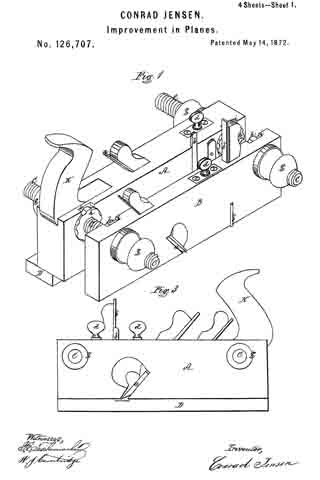
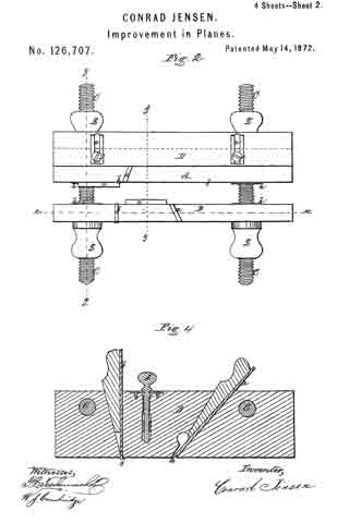
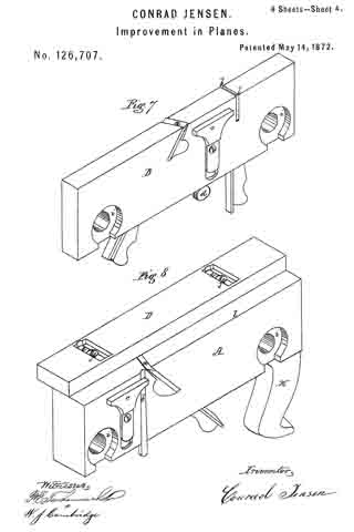
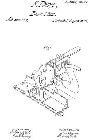
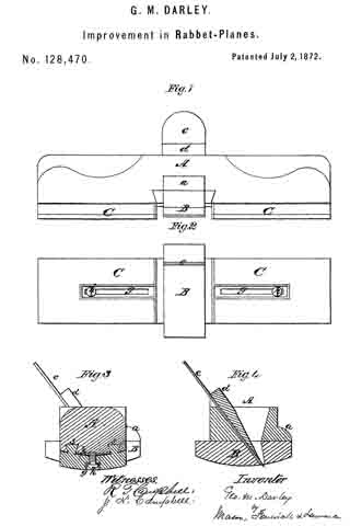
Figure 1 is a front view of the plane. Fig. 2 is a bottom view of the plane. Fig. 3 is a section through dotted line x x. Fig. 4 is a section through dotted line y y.

Similar letters of reference indicate corresponding parts in the several figures.

This invention relates to an improved plane, which is designed for rabbeting circular as well as oval work. It consists in the combination of adjustable gauges with a plane, as will be hereinafter explained.

The following description of my invention will enable others skilled in the art to understand it.

In the accompanying drawing, A represents the stock of the plane, which may be made of any desired length, and which is curved on top at its ends so that it can be conveniently grasped in the hands. This stock A is centrally throated to receive the plane-iron c and wedge d, and beneath this throat the sole or face B of this plane is secured in a suitable manner. This sole presents a convex surface, which is below the corresponding surface of the stock. It is convex transversely, and its ends extend out from the front and back sides of the stock A, as shown in Figs. 2, 3, and 4.

The front projecting end of the sole B is sustained against undue strain by a shoulder, a, which is formed on the stock A. On each side of the sole B is a gauge, C, the wearing face of which is protected by metal. Each gauge C is adjustable endwise, and is applied to the stock A by means of dovetail tenons s s, shown in Fig. 3. Each gauge is slotted longitudinally, as shown at g, which slot receives through it a set-screw, h, which is tapped through a plate, p, on the bottom of the stock, and serves to fix the gauge at any desired point. Instead of a set-screw, h, a bolt may be used for each gauge G, which will pass vertically through the stock A and receive on its upper end a nut.

It will be seen from the above description that I have a right and left hand rabbeting-plane, which can be adjusted for any desired width of rabbet by means of the gauges C, and which is adapted for all kinds of circular or oval work.

Having described my invention, what I claim as new, is —

The centrally-throated stock A, with its depressed sole B, in combination with the adjustable gauges C C, substantially as described.

GEORGE M. DARLEY.

Witnesses:
Z. N. CAMPBELL,
EDM. F. BROWN.

No. 126,707 – Improvement In Planes (Conrad Jensen) (1872)

[paiddownloads id=”194″]126707


UNITED STATES PATENT OFFICE.

_________________

CONRAD JENSEN, OF BOSTON, MASSAOHUSETTS.

IMPROVEMENT IN PLANES.

_________________

Specification forming part of Letters Patent No. 126,707, dated May 14, 1872.

_________________

To all whom it may concern:

Be it known that I, CONRAD JENSEN, of Boston, in the county of Suffolk and State of Massachusetts, have invented certain Improvements in Planes, of which the following is a full, clear, and exact description, reference being had to the accompanying drawing making part of this specification, in which —

Figure 1 is a perspective view of my improved plane. Fig. 2 is a plan of the under side of the same. Fig. 3 is an elevation of the side of the plane opposite to that shown in Fig. 1. Fig. 4 is a longitudinal vertical section on the line x x of Fig. 2. Fig. 5 is a transverse vertical section on the line y y of Fig. 2. Fig. 6 is a transverse vertical section on the line z z of Fig. 2. Fig. 7 is a perspective view of one portion of the plane detached and inverted. Fig. 8 is a perspective view of the other portion inverted. Fig. 9 is a plan of the under side of the portion of the plane shown in Fig. 8, with the gauge removed.

In “matching” boards of varying thicknesses it is customary to employ a “plow” plane for cutting the grooves, the plane being made adjustable, so as to insure the groove being in the required position, different irons being used for grooves of different widths. To cut tenons corresponding thereto has, however, heretofore necessitated the employment of a number of separate tools (one for each size of tenon) which were expensive, and required much time and care to keep in order. My invention has for its object to overcome these objections; and consists in a combination plane formed of two portions, each provided with an iron, and made adjustable to and from the other, by which construction tenons of various widths and depths may be cut in any desired position with one and the same tool, which can also be used as a “dado” plane; the two portions, (which are provided with suitable gauges and cutters,) when separated furnishing a “dado” plane, two “rabbet” planes, and a “lillister” plane.

To enable others skilled in the art to understand and use my invention I will proceed to describe the manner in which I have carried it out.

In the said drawing, A B represent the two portions of my improved plane, connected together by screws C provided with nuts. Each of the portions A B is provided with an iron, a, set at an angle, a vertical cutter, b, in front thereof, and a sliding gauge, c, on one side, operated by a thumb-screw, d. D is a longitudinal gauge, provided with slots e, and secured by screws f to the under side of the portion A. The screws C are each provided with two nuts, g g, one on each side ofthe plane, and also with two nuts, h h, between the two portions A B, and ntting into recesses i i, formed therein, in order that the two portions may be brought nearly together; and it is by means of these nuts and screws that the portions A B are held firmly in position at any required distance from each other. The portion A is provided with a handle, K, by which the plane is operated. When it is desired to cut a tenon at a given distance from the edge of a board, the gauge D is set at a corresponding distance from the inner edge l of the portion A. The distance apart of the portions A and B is now made to correspond to the required width of the tenon by operating the nuts g h, and the gauges c are then adjusted to make the distance from their under side to the bottom of the portions A B equal to the required height of the tenon. It will thus be seen that I am enabled by a single plane to make a tenon of any required width and depth on a board or plank of any thickness, and situated at any required distance from its edge; whereas, it has heretofore required a diiferent tool for every different size of tenon, which was necessarily in the center of the thickness of the board.

My improved plane may also be used as a “dado” plane, to cut a groove at any required distance, within the limits of the length of the screws C, from the edge of a board, by entirely covering the iron a of the portion A with the gauge D, and adjusting the portion B at the required distance from the portion A, when the plane may be operated, as seen in Fig. 6, the gauge D resting against the edge of the board, and serving as a guide, and also preventing the iron a of the portion A from cutting. The depth of the groove thus cut by the iron a of the portion B is regulated by its gauge c, and its double cutter b acts in advance of the iron a in the usual manner.

When a groove is to be cut beyond the limits of the screws C the portion B is separated from the portion A and used alone, in which case it becomes an ordinary “dado” plane, and requires to be moved against a guide-strip, temporarily secured to the board, to give the required direction to the groove.

By removing the double cutter b and gauge c from the portion B, when detached, it becomes an ordinary narrow “rabbet” plane, which is a great advantage, as it has heretofore been impossible to convert a “dado” plane into a “rabbet” plane, on account of the shoulder on its under side.

When the portion B is detached, the portion A with its gauge D becomes a “fillister” plane, and by removing the gauges C D from the portion A it becomes a broad “rabbet” plane, a change which it has heretofore been impossible to make, for the reason that the iron in an ordinary “Fillister” plane extends only part way across its under surface, which prevents it from being used as a “rabbet” plane.

From the foregoing it will be seen that I combine in a single tool a tenon-cutter for cutting tenons of all sizes in every desired position, a “dado” plane, a “fillister” plane, and two “rabbet” planes, of different widths, while but two irons are used, which do not require to be changed in performing the various operations above referred to, and I am thus enabled to effect a great saving in tools and in the space required for the same, as well as in the labor of grinding, and care required to keep them in order.

What I claim as my invention, and desire to secure by Letters Patent, is —

I claim the tool as described, as a new article of manufacture.

Witness my hand this 5th day of March, A.D. 1872.

CONRAD JENSEN.

In presence of —
P. E. TESCHHMACHER,
W. J. CAMBRIDGE.

No. 106,868 – Improvement In Carpenters’ Planes (Russell Phillips) (1870)

[paiddownloads id=”171″]106868


UNITED STATES PATENT OFFICE.

_________________

RUSSELL PHILLIPS, OF BOSTON, MASSACHUSETTS.

IMPROVEMENT IN CARPENTERS’ PLANES.

_________________

Specification forming part of Letters Patent No. 106,868, dated August 30, 1870.

_________________

To all whom it may concern:

Be it known that I, RUSSELL PHILLIPS, of Boston, in the county of Suffolk and Commonwealth of Massachusetts, have made an invention of a novel and useful implement which I term a Carpenter’s Combination-Plane; and I do hereby declare the following to be a full, clear, and exact description thereof, due reference being had to the accompanying drawings, making part of this specification, and in which —

Figure 1 is a perspective view; Fig. 2, a plan; Fig. 3, a side elevation; Fig. 4, a vertical section.

This invention combines in one implement elementary features now only found in several independent tools, the result being a great saving in space in transportation, as well as in stores and carpenters’ shops, and enabling a mechanic to obtain, at small comparative cost and in a compact and efficient form, the substitutes for several classes of planes.

I have combined in this instrument a rabbeting-plane and an expansible matching-plane, to operate on and prepare boards of various thicknesses, one side of said rabbeting-plane serving as a fence or guide to the latter, as hereinafter explained.

While this invention consists, primarily, of the combination of a rabbeting-plane and an expansible matching-plane, the latter, in turn, will be found to consist of several members, so organized as to enable one to produce a “tongued groove-connection,” called “matching stuff,” a “cross-channel,” or a “plowed groove of any desired dimensions.”

In the drawings accompanying and illustrating this description of my invention, A denotes a rabbeting-plane, substantially of ordinary construction, with the exception of the removal of the handle, and the erection, at or about its center, of a post or standard, B, which slopes forward at a slight angle, and over the iron ofthe plane, which latter is represented at C. The plane A is further distinguished from others of its class by the addition to its under side of an adjustable gage, D, which converts it into a species of plane called “fillister,” or those in which the width of the rabbet cut by the tool is governed at pleasure.

The standard B supports from its upper part a long horizontal lateral bar or arm, E, departing from it at right angles to the length of the plane, such arm supporting the two movable cutter heads or stocks, which, with their adjuncts, constitute the expansible or variable matching-plane before alluded to, the arrangement of parts, as hereinafter explained, being such that both cutter-heads may be moved together or singly upon the arm and away from the rabbeting-plane A, or toward and away from each other thereupon, the side ofthe rabbeting-plane next adjacent to the said cutter-heads serving, under all circumstances, as a gage or “fence,’ so called, to the matching-plane.

The main or primary cutter-carrier is shown at F in the drawings as composed of a plate or portion, a, sliding upon or against the rear side of the arm E, and connned to such arm, upon which it slides, by clamp-nuts and bolts b b, or their equivalents, the inner end of the said plate a terminating in a right-angular bend or head, c, carrying upon its face the “spur or scoring iron,” such spur-iron a’ being secured in position thereupon by side projections or hooks, e e, and a set-screw, f, as represented, and performing the duties of preparing the way for either one or both of the matching cutters, as the case may be.

Upon the front or inner face of the cutter-carrier F or its cutter-head c, I apply a flat plate or second cutter-head, g, this latter object sliding vertically upon the head c, and being confined thereto by a set-screw or other device. The cutter-head g carries upon its inner face a cutter or iron, h, for cutting or plowing a groove, the relationship of the two cutter-heads being such that the head g may be lowered into a working position, or elevated above the same, while the cutter It may be raised or lowered with respect to its head, according to the depth of cut required, it being understood, as before stated, that when the said cutter (or its companion, to be duly referred to) is at work the side or fence i of the rabbeting-plane A serves as a guide or gage to determine the width of the cut thus made.

The iron or cutter It is composed of an upright flat plate, the lower part of which is bent into an angular sloping portion, which, constitutes its cutting-edge, the cutter by this means saving the necessity of employing two spurs to prepare its way, while the lower edge of the head g serves as a “sword,” so called, to determine the thickness of the shaving cut by the said cutter.

The cutter h, may be employed alone, in connection with the rabbeting-plane, to cut a channel, whether such groove be an ordinary cross-groove or the groove required to receive the tongue of the next adjacent board in “matching stuff,” or the said cutter may be employed in connection with the cutter to cut away one side of the tongue used in said operation of matching stuff; or, again, should occasion require, the cutter or iron h may be lowered and work in conjunction with the rabbeting-plane A, thus cutting at one and the same time a rabbet and groove or channel.

The second cutter, before mentioned, is shown at j in the accompanying drawings as mounted upon the inner face of a second cutter-head, k, which makes part of a carrier, l, mounted and sliding upon the first carrier, F, and confined thereto, by clamp-nuts or set-screws, in any proper manner, it being observed that the construction and relationship of this latter cutter-carrier and head with respect to the former being substantially the same as the former in respect to the arm or support E, before mentioned, it being observed that while the cutter or tool may be moved toward or away from the rabbeting-plane, for the purpose of cutting channels of varying width, the two cutters may be separated or contracted, in order to cut a tongue of any given width up to a certain extent.

Upon the outer or remote side ofthe second cutter-head, k, is disposed an adjustable gage for determining the depth of the cut made by either one or both the cutters h or j, (in connection with the rabbeting-plane as a side gage,) to produce a cross-channel or plow a groove.

As it becomes necessary to produce a sword to regulate the thickness of the shaving cut by the second cutter or iron, j, I form it (the sword) upon the under side of a fiat plate, o, which in turn is suspended from the under side of the carrier l, applied adjustably thereto, and confined in place by set-screws or their equivalents, in order that the lateral position of the said sword with respect to the said cutter j may be varied, as it sometimes becomes desirable that this sword shall travel in the center, or thereabout, of the groove or channel formed by such cutter.

Upon the upper side of the rear extremity of the sword, which is shown at p, or its supporting-plate o, I mount the handle of the combination-instrument, such handle being represented at q in the drawings.

An instrument constructed and organized as above explained may be used as a rabbeting-plane, or fillister simply.

By lowering the cutter h, to the proper extent and employing the side of the rabbeting-plane as a guide or gage, a cross-channel may be cut or a groove may be plowed.

By lowering the second cutter, j , and adjusting the distance between the two to the width of tongue required in machine-stuff, such tongue will be cut to any desired gage, or, as before stated, the second cutter, j, maybe employed alone, in connection with the spur-iron a’, to cut a channel or groove.

For extreme variations in the extent of cuts made by my present invention, I shall adapt cutters of varying widths; but it will be evident that considerable variations maybe made without removing the cutter at the time in use.

In the use of the rabbeting-plane alone, the cutter-head c should be inverted end for end to serve as a gage.

Although I have in the present instance represented one of the cutter-carriers as supported and sliding upon the arm E and the other carrier applied in similar manner to the first, I would remark that I intend applying each carrier by itself to the bed or frame of the tube.

I claim —

The herein-described carpenter’s plane.

RUSSELL PHILLIPS.

Witnesses:
EDW. GRIFFITH,
FRED. CURTIS.

No. 52,478 – Improvement In Saw Rabbet Planes (Daniel D. Whitker) (1866)

No. 52,478 – Improvement In Saw Rabbet Planes (Daniel D. Whitker) (1866)

[paiddownloads id=”113″]52478


UNITED STATES PATENT OFFICE.

_________________

DANIEL D. WHITKER, OF HUDSON, NEW YORK.

IMPROVEMENT IN SAW-RABBET PLANES.

_________________

Specification forming part of Letters Patent No. 52,478, dated February 6, 1866.

_________________

To all whom it may concern:

Be it known that I, DANIEL D. WHITKER, of the city of Hudson, in the county of Columbia and State of New York, have invented a new and useful Tool or Instrument for Rabbeting and Plowing or Grooving Lumber, which I call or denominate the “Saw-Rabbet;” and I hereby declare that the following is a clear and exact description of the construction and operation of the same, reference being had to the annexed drawings, making a part of this specification, in which —

Figure 1 is a perspective view. Fig. 2 is a longitudinal or side elevation; and Fig. 3 is a transverse section or end view.

The nature of my invention consists in combining an adjustable saw with an adjustable fence or gage, both being attached to a stock with handle similar to a plane, forming together a tool combining the properties of the joiner’s plow and fillister.

To enable those skilled in the art to make and use my invention, I will proceed to describe its construction and operation.

I construct my saw-rabbet with stock and handle similar to a plane, but without mortise for the iron. To the outside of this stock I attach, by means of the screws a a’ a”, an adjustable saw, A. The slots s s’ s” in the saw enable it to be set up or down, so as to cut any desired depth. This saw may be of any required thickness for inserting panels, or by means of the adjustable fence or gage C, attached to the bottom ofthe stock B by the screws b b’ through the slots c c’, may be made to saw one, two, or more cuts or grooves at any desired distance from the edge for rabbeting, or a part for grooving, and the intermediate wood removed by a chisel or ordinary rabbet-plane. But the saw-rabbet is specially adapted to cutting grooves for inserting the rubber weather-strip, and the only tool that can be used advantageously for that purpose. In addition to the foregoing it will do all the work of both the fillister and the plow. lt can also be easily converted into a useful tool for rabbeting on curves or circles by setting out one or both ends ofthe saw by means of curved wedges or thumb-screws. A steel spring fence or gage may then be employed and be set out with the saw.

The stock to which the saw is attached may be of wood or metal. The friction-rolls o o’ o’
in the front edge ofthe gage rest or fence are employed to lessen the friction in operating the saw-rabbet.

The operation of this instrument needs no explanation. It is employed precisely like the fillister and plow, the operation of which is well understood by all carpenters and joiners, and indeed by all who have any acquaintance with these tools.

What I claim as my invention, and desire to secure by Letters Patent of the United States, Is —

Combining and arranging the adjustable saw A with the adjustable gage-rest G, substantially in the manner and for the purpose herein set forth.

DANIEL D. WHITKER.

Witnesses:
FRANK A. MACY,
WILLARD S. WOOD.

No. 7,938 – Tonguing, Joining And Rabbeting Plane (John A. Fry) (1851)

[paiddownloads id=”6″]7938


UNITED STATES PATENT OFFICE.

_________________

JOHN A. FRY, OF EDINBURG, VIRGINIA.

TOOL FOR TONGUING, JOINING, AND RABBETING.

_________________

Specification of Letters Patent No. 7,938, dated February 18, 1851.

_________________

To all whom it may concern:

Be it known that I, JOHN A. FRY, of Edinburg, county of Shenandoah and State of Virginia, have invented a new and useful Tonguing Plane, and that the following is a full, clear, and exact description thereof, reference being had to the accompanying drawings, which make part of this specification.

The purposes of my invention are to make a tool by the use of which the workman may make tongues of different thicknesses, the same tool being capable of both tonguing and jointing the stuff, and to make the same tool answer the purpose of a rabbetlng plane. The tool might be called a combined jointing-tonguing and rabbeting plane. The advantage of such a tool is that boards or plank of different thicknesses may be tongued with one implement, and yet each may have a tongue out upon it of a thickness adapted to that of the plank. It also enables the workman to diminish the thickness of any tongue if found too thick for the easy putting together of his work. It also saves the trouble of keeping on hand or carrying about three distinct tools instead of one, to perform the three or four operations for which this implement is intended.

My plane is made of two distinct parts or bodies B and B’, Figures 2 and 3; wherein, Fig. 2, is an underside plan and Fig. 3 a top plan. These parts may, by turning back the screws s, s, and screwing up the nut N, N, on the screws S, S, be brought close together, closing up the space m m between the two bodies. When the bodies are thus brought together, the instrument may be used first to joint a board, which it will do if the adjustable guide or gage G, Fig. 2, be brought into the position indicated by the dotted lines, G’. This position it can take by slackening the set screws r r, and slipping the gage piece till the screws occupy the opposite ends of the slots o, o, to those where they are seen in the figure. The plane iron P’ will then serve as a jointing cutter to straighten the edge of the board before commencing the tonguing, the board resting on its edge for both operations.

When a tongue is to be cut, after jointing the board, the slide or gage G is restored to the position seen in the figure (2) or so nearly to it as is required by the thickness of the plank. The two bodies B, B’ may then be either kept close together or they may be separated apart to a distance required by the thickness of the tongue intended to be formed. If they be kept close together the thickness of the tongue will be that of the two half grooves P, P’, but if they be separated by the adjusting screws s s, and fixed by the set screws S S, then will the thickness of the tongue be increased by the distance m of the separation of the two bodies. At whatever distance apart the bodies are set the guide or gage G, sliding along the face of the board determines the breadth of out which shall be made by the cutter P. The cutters P and P’ are both set inclined not only backward from the vertical, but also horizontally from their inner to their outer edges respectively. By this arrangement of the irons the chips or shavings are, when tonguing, thrown outward on the two opposite sides of the plane. The place of discharge is seen at R, in the side elevation of the body B, Fig. 1. The cutters P and P’ are held in place by the oblique wedges W and W’ Figs. 1 and 3.

The cutters have each two edges, one across the end and one on the inner side, whereby the side of the tongue is smoothed at the same time that the wood is cut away on both sides of it to form the jointed shoulders of the tongue. The edges along the sides also serve the purpose of diminishing the thickness of a tongue already made when such diminution becomes necessary.

The handle of the plane is seen at H, Figs. 1 and 3. It is permanently attached to the body B, but its base Q Q (Fig. 3) extends beyond that body and makes a projection which enters a notch M M, in the upper part of the body B’, which notch and projection serve to give a support in a longitudinal direction to the body B’ while the set screws S S confine it laterally to the body B.

When the plane is to be used for rabbeting the body B’ is wholly removed and the set screws S S may be taken out. Then by sliding the guide G on the set screws r r, till the edge w w coincides with or lies over x x, it may be then fastened for the purpose of using the plane to joint a board previous to cutting a rabbet. The plane iron P is driven down till its cross edge comes nearly or quite through the oblique slot V. The edge of the gage G together with the vertical side of the notch P, then serves as the face of the jointer, and the jointing cut is made not by the cross edges but by the side edge of the plane iron P. With the implement having its gage and cutter in the positions just described the board is jointed on its edge while it lies upon its face or flat side, the bottom of the notch or rabbet p resting upon the upper corner of the board and guiding or sustaining the plane.

The board having been jointed, is rabbeted without removing it from the bench. For this purpose, the tool is prepared by sliding the gage G into the position represented by the plain lines in Fig. 2, and the plane iron is set with its cross edge nearly on a level with the line x x, descending only far enough below that level to make its cut.

It is then used to out the rabbet without changing the position of the board, from that in which it lay while being jointed.

From the foregoing description it will be seen that the gage G is brought into use in combination with the notch P and the side edge of the cutter P to form a jointer for a board resting on its face, in a situation to be rabbeted ; that it is combined with the cross edge of the cutter P and with the half groove p to form the rabbeting plane; that when combined with the cutter P’ and the body B’ it forms a jointing cutter to joint a board, set up edgewise in a position to be tongued, and finally that the same gage G in combination with the two bodies B and B’, and the two cutters P and P’, it forms the tonguing plane. The parts of the tonguing plane just specified, together with the parts hereinbefore specified for setting the bodies B and B’ asunder and retaining them in place constitute an adjustable tongue cutter, whereby tongues may be out of different thicknesses to suit the thickness of the stuff or the purpose to which it is to be applied.

Fig. 4 is a cross section through x x Fig. 3, exhibiting the bodies B and B’ the gage G, the fastening screw S and its nut N together with an elevation of the wedges W, W’, plane irons P and P’ and the handle H.

What I claim as my invention and desire to secure by Letters Patent is —

1. So making a jointing, tonguing and rabbeting plane that the jointing and tonguing of a board while resting on its edge, and also the jointing and rabbeting of it while it lies on its flat side may all be performed with one planing tool in the manner substantially as herein described, and for the purposes herein set forth.

2. I also claim making the tonguing hand plane in such a manner as to enable the workman to make therewith tongues of various thicknesses substantially in the manner herein set forth, whereby I prevent the necessity of providing different tools to tongue planks of different thicknesses.

3. I also claim in combination with a divided body or plane stock, the two cutters having each a cross-cutting and a side-cutting edge and the means substantially as herein described for adjusting the distance apart of the two cutters and bodies whereby the plane is made capable of dressing the sides of a tongue to any desired thickness and at the same time to cut the shoulders as herein specified.

4. I also claim in combination with the gage G the use of the body B’ and the cross edge of the cutter P’ to constitute a jointer to straighten the edge of a board preparatory to tonguing it and while resting on its edge in a situation to receive the tonguing.

5. I also claim the gage G in combination with the notch p and the side edge of the cutter P, acting as herein described, as a jointing plane to straighten the edge of a board or plank resting on its flat side, in a position to have a rabbet out in the manner substantially as herein set forth.

JOHN A. FRY.

Witnesses:
GEORGE A. GRUNDSTAFF,
ISAAC RULY.