No. 19,130 – Crozing Plane (S.G. Crane) (1858)

[paiddownloads id=”69″]19130


UNITED STATES PATENT OFFICE.

_________________

S. G. CRANE, OF ROCHESTER, NEW YORK.

CROZING-PLANE.

_________________

Specification of Letters Patent No. 19,130, dated January 19, 1858.

_________________

To all whom it may concern:

Be it known that I, S. G. CRANE, of Rochester, in the county of Monroe and State of New York, have invented a new and useful Improvement in Crozing-Planes for Coopers; and I do hereby declare that the following is a full and exact description thereof, reference being had to the accompanying drawings and to the letters of reference marked thereon.

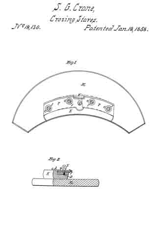
Figure 1, is a plan of the instrument.
Fig. 2, is a transverse section.

The nature of my invention consists in constructing crozing planes with two adjustable circular plates P so arranged as that their radius may be changed to suit barrels, half barrels, &c., and in attaching the knife V to one of said plates P.

The “board” M, I construct in the usual way also the block K. The plates P, are attached to said block by screws J. There are slots in the plates for the screws J to pass through, and they permit the changes shown by the dotted lines in Fig. 1. The slots are covered by the Washers C.

The knife V is attached to the rear plate P by the screw Y and its nut D. Said nut is a flat plate of about the same size as the shank of the knife, and answers as a gage for the depth of cutting when the plates are set out for smaller circles, as seen in Fig. 1 by the dotted lines, and at such times the knife V requires no readjusting, it being adjusted to the rear plate, is moved with it.
The spur B on the rear plate answers as a gage for the other plate.

What I claim, is —

The construction and arrangement of the adjustable plates P, and the arrangement of the knife V, as, and for the purposes specified.

S. G. CRANE.

Witnesses:
FERDINAND SEIFRIED,
LOUIS ERNST.

No. 23,928 – Improved Bench Plane (William S. Loughborough) (1859)

[paiddownloads id=”82″]23928


UNITED STATES PATENT OFFICE.

_________________

W. S. LOUGHBOROUGH, OF ROCHESTER, NEW YORK.

IMPROVED BENCH-PLANE.

_________________

Specification forming part of Letters Patent No. 23,928, dated May 3, 1859.

_________________

To all whom it may concern:

Be it known that I, WM. S. LOUGHBOROUGH, of Rochester, in the county of Monroe and State of New York, have invented a new and useful Iron Fillister-Plane, the principles of which are applicable, with slight modifications, to panel-plows, match-planes, dados, rabbets, and to bench-planes; and I do hereby declare that the following is a full and exact description of its construction and operation, reference being had to the accompanying drawings, and to the letters of reference marked thereon.

Figure 1 is a side elevation. Fig. 2 is a plan of the race. Fig. 3 is a plan of the parallel fence F. Fig. 4 is an elevation ofthe reverse side of Fig. 1 without the handle, and showing the shape and position of the stop P, also of the spur M.

The nature of my invention consists, first, in the construction of an iron stock for fillisters, dados, rabbets, rnatch-planes, and panel-plows; second, in the construction of a parallel fence, F, for fillisters and match-planes; third, in the construction and arrangement of a stop, P, moving diagonally to the line of pressure upon it, the same being applicable to the dado and panchplow; fourth, in the application and arrangement of the spring-cap G, in combination with the screw 2 or any other adjustable or lined fulcrum; fifth, the combination of the adjusting-screw 1 with the bit B and spring-cap C; sixth, the application and arrangement of the spur M.

I construct the plane-stocks, as seen in Figs. 1 and 4, with an arch, N, which connects the face in front of the throat with that in the rear, and at the same time affording a cutting-edge to the bit B the full width of the face of the plane. The projection R governs the position of the bit. The screw 2 passes through the slot of the bit and into this projection, and the adjusting-screw 1 screws through the said projection and against the upper end of the bit B, so that by turning the said adjusting-screw up the edge of the bit is thrown below the face of the plane, causing it to cut a thicker shaving, and vice versa, whereby the operator is enabled to adjust the “cut” of the bit to the rnerest fraction, and in an instant.

The parallel fence F, I construct, as seen in Fig. 3, with the slots D, through which the screws Y pass, running out from the face of the fence at an angle of sixty degrees, more or less, so that when the nuts 4 and 5 are loosened to make changes one measurement only is required, for neither end can move up or back faster than the other when the screws Y are properly tilted to the slots D.

The stop P is made and arranged, as seen in Fig. 4, with the slot for the set-screw K, in this also running up diagonally from its face, so as to prevent any possibility of the downward pressure of the plane when it has worked to the desired depth from forcing the stop up, and thereby allow it to work too deep. It is kept in its proper position by the guide-pin U.

The handle H is cut to lit under the projection R, and the screw 7, Fig. 2, is put through the face of the plane and into the handle, which holds it firmly to its place.

The spur M, Figs. 2 and 4, is made of plate-steel and fitted into a dovetail seat, where it is held by the screw 6, which has a bevel or a countersunk head, one side of which is pressed against the spur when the screw is turned in.

The projections J are to allow the fence to be adjusted to the full width of the face of the plane. The rib X is to strengthen the arch N.

There may be a slip, V, of wood let into the fence F to prevent the edge of the bit from coming in contact with the iron when the bit is being taken out or replaced.

What I claim as my invention is —

1. The combination of the screw 2, (which takes effect in the projection R,) spring or yielding cap C, bit B, and screw 1, for the purpose of varying the cut of the bit, and at the same time and proportionally the space of the throat, the base of the bit B being the fulcrum upon which it swings when said changes are made, the said combination being applicable for the adjustment of the bit in all kinds of planes.

2. The adjustable parallel fence F, constructed with diagonal slots D for the set-screws Y, as and for the purpose specified, said fence being applicable to match-planes, and also the stop P, with the slot running up diagonally from the face, the set-screw K, and the guide-pin U keeping it in position, said stop being applicable to panel-plows and dados.

WM. S. LOUGHBOROUGH.

Witnesses:
CHARLES GILBERT,
RICHARD GILBERT.

No. 42,585 – Improvement In Grooving Or Panel Plows (William S. Loughborough) (1864)

[paiddownloads id=”103″]42585


UNITED STATES PATENT OFFICE.

_________________

WILLIAM S. LOUGHBOROUGH, OF ROCHESTER, NEW YORK.

IMPROVEMENT IN GROOVING OR PANEL PLOWS.

_________________

Specification forming parts of Letters Patent No. 42,585, dated May 3, 1864.

_________________

To all whom it may concern:

Be it known that I, WM. S. LOUGHBOROUGH, of Rochester, in the county of Monroe and State of New York, have invented a new and useful Panel-Plow or Grooving-Plane; and I do hereby declare that the following is a full, clear, and exact description thereof, reference being had to the accompanying drawings, making a part of this specilication, in which —

Figure 1 is an elevation of the left side of the plane. Fig. 2 is an elevation of the right side. Fig. 3 is an end view of the fence B detached, showing the front arm, C.

Similar letters of reference indicate corresponding parts in the several figures.

The nature of my invention consists, mainly, in the peculiar construction of the stock of panel-plows or other grooving-planes ; also, in a novel and efficient means for securing the adjustment of the fence by simply turning one screw, and in an improved manner of securing the bits in this class of planes.

A in the drawings represents the skeleton stock; B, the fence; C and C’, the arms; D, the thumb-screw ibr fastening the bit; E, the screw for fastening the arms of the fence; a, the screw for holding the stop S ; G, the bit ; b and b’, the clamping-bars, and w the wedge, which is operated upon by the screw E, by which it is driven down between the end of the bars b and b’, causing them to clamp firmly against the arms of the fence and to hold it securely in position. The wedge should be made sufficiently obtuse to cause it to recede from between the bars whenever relieved by the screw.

The body or stock A of the plane is made, as seen in the drawings, with an enlargement, d, running diagonally across and projecting equally on each side. Within this enlargement is formed a mortise, through which the bit G is placed. This mortise should be five-eighths to three-fourths of an inch wide, and it is recessed on the front or upper side, as indicated by the dotted lines, which is done by enlarging the core. Said core should also have a projection on the right side, near the lower end, to form the opening under the clasp f for the bar b1’ to pass through. The clasp g is formed by “coping out” in molding, part ofthe stop being removed, as seen in Fig. 1, to show the recess. The oval-shaped recess in which the wedge w is placed is formed in the same manner, and is made deep enough to receive the upper end of the bars b and b’ and the thickness of the flange i. The clasp g is extended over the upper rib of the arm G, and a similar bearing is provided over C’ by the projection a. These bearings prevent the arms from “tilting” when released by the screw E. The projections J should be long enough to prevent any cramping of the arms when the fence is being moved either way, and also to secure its parallel movement, it being cast or otherwise rigidly fixed to the arms.

The stop S is secured between the diagonal ribs r by the screw a, which may have a milled head, if desired. The ribs r are cast with the stock, and they receive all the diagonal strain coming upon the stop, thereby relieving the screw a from all lateral strain. The stock A is thickened by the button u (seen in Fig. 2) to increase the threaded bearing ofthe screw a.

The arch N of the throatway may be formed on either side ofthe stock, but the right hand side is probably preferable.

The bits G are made of uniform thickness from end to end, and are provided, the same as other plow-bits, with a central groove in the back side, which rides the front end of the rear plate, P’, and they are so fitted in the mortise as to have a bearing at t before they strike the rest at v, against which they are forced by the screw D and firmly held. This manner of fitting the bits, always effecting a perfect bearing of the bit at t, whether a wide or narrow one is used, insures the discharge of the shavings.

The plate p projects each side across the stock so as to form the seat for the handle H centrally behind the bit. The handle is held against the side plate, lt, by the screw s, and the rear end is firmly held in position by a screw through the base plate p at y.

The fence B may be removed at any time without deranging the clamping devices, the flange i of the wedge to preventing the end of the bars b and b’ from falling out. There is a shoulder on the back side of b’ at e, Fig. 2, which strikes against the case of the bit-mortise, and thus prevents the bar from dropping away from the flange i, and b is kept in position longitudinally by the point c resting against the stock.

If desired, the arms G and C’ may be made separate from the fence B and attached thereto by screws or otherwise; but I prefer to cast them together, as shown in the drawings.

Among the many advantages afforded by making these tools of metal instead of wood are the following: They are much less cumber-some, are more durable, the parts are much more readily and perfectly adjusted, they work better and easier, because they never choke or clog with the shavings, and they can be sold for less than one-half the cost of wooden planes of the same variety.

The plates P and P’ are cast on the stock A, thereby avoiding the labor and expense of fitting and attaching them by screws or other-wise.

What I claim as my invention, and desire to secure by Letters Patent, is —

1. The above-described panel plow or plane, when constructed, arranged, and combined in the manner and for the purposes specified, as a new article of manufacture.

2. Securing the gage of the fence B at any desired point by operating a single screw, E, substantially in the manner specified.

WM. S. LOUGHBOROUGH.

Witnesses:
A. C. DICKINSON,
A. H. BILLINGS.