No. 799,234 – Carpenter’s Plane (John Jett) (1905)
[paiddownloads id=”624″]799234


UNITED STATES PATENT OFFICE.

_________________

JOHN JETT, OF SAN FRANCISCO, CALIFORNIA.

CARPENTER’S PLANE

_________________

799,234. Specification of Letters Patent. Patented Sept. 12, 1905.
Application filed August 18, 1904. Serial No. 221,296.

_________________

To all whom it may concern:

Be it known that I, JOHN JETT, a citizen of the United States, and a resident of San Francisco, in the county of San Francisco and State of California, have invented certain new and useful Improvements in Carpenters’ Planes, of which the following is a specification.

The objects I have in view are, first, to produce an adjustable plane in which the bit or plane-iron is held more firmly and is more easy to adjust than heretofore; second, to produce an adjustable plane in which the different parts are less liable to become disarranged than heretofore; and to this end the main feature of my invention consists in providing a roller which extends across the plane in front of the bit and about midway between the top and bottom of the plane-stock and having an improved gearing between the roller and bit by which the bit is given a slow and positive movement and by which the bit is held in any position without the use of any locking device.

Another feature is to have the roller connected to a lever on the outside of the stock and have a lug to hold the lever in place and prevent end movement of the roller.

Another feature is to provide a hood above the roller to protect, strengthen, and afford a continuous bearing for the same.

Another feature is to hold the bit and cap-plate more firmly together so they will not become disarranged when the bit is carried under the roller.

Another feature is to have the gearing adjustably attached to the cap-plate, so that the lever will occupy a convenient position when the bit is clamped to the stock.

These features are more fully described in the following specification, reference being had to the accompanying drawings, which form a part thereof.

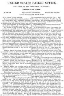
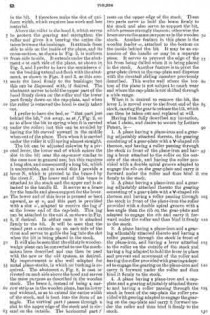
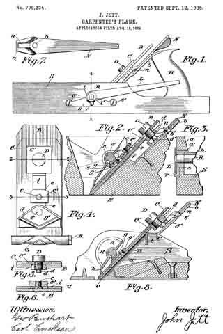
Figure 1 is a side view of my improved plane ready for use. Fig. 9. is a longitudinal sectional view of the central part of the plane, showing the mechanism by which the bit is adjusted. Fig. 3 is an enlarged cross-section of the plane on the line 1 1 of Fig. 1, showing a sectional view near the left-hand side of the plane looking forward, the bit cap-plate and gear-plate not being shown. Fig. A is a top view of the gear-plate, cap-plate, and bit in their proper position, the roller being shown crosswise at the bottom. Fig. 5 is a cross-section on the line 2 2. of Fig. 4. Fig. 6 is a cross-section on the line 3 3 of Fig. 4. Fig. 7 is a top view of the lever for adjusting the bit sidewise. Fig. 8 is a longitudinal sectional view of the adjusting mechanism as applied to metal plane-stocks.

Similar letters refer to similar parts throughout the several views.

In the drawings, the letter S represents the plane-stock, which is cutout at the middle to receive the bit, the same as in the old-style wooden-wedge plane-stock. The stock is then cut to receive the bushing x, of which there is one on each side of the stock, and is held thereto by the screws x’, which enter the solid part of the stock, as shown in Fig. 2. The bushing serves as a bearing to receive the roller R, which extends through the stock about midway between the top and bottom in front of the bit. The roller is actuated by the lever L, which is rigidly attached thereto and is usually placed on the left-hand side of the plane, as shown in Fig. 1. These parts are held in place by the lug r on the bushing, a part of this lug being cut away to receive the beveled part l on the lever, and this beveled part is cutaway, as at l’, so as to pass the lug, and thus allow the roller to be removed and replaced at will.

The roller is provided with a double spiral groove G, Fig. 4, adapted to receive the V-shaped rib g on the gear»plate g’ I prefer to have this rib with a wider angle than the groove in the roller. Then the rib and groove will not be in exact alinement, and the groove itself is cut wider to receive the rib. This will cause the gear-plate to have a slower movement when compared with the roller and will give a finer adjustment of the bit.

The gear-plate is pivoted to the dovetail sliding member e bythe rivet e’. This member slides in the dovetail slot i, Fig. 6, in the cap-plate C and is made adjustable thereto by the bolt c and the nut c’. The cap-plate has a small section C’ cut out near its upper end, and this section is made adjustable to the bit B by the cap-bolt D and the nut d, which moves up and down in the dovetail slot i’ in the bit, and when the bolt is tightened the nut will be wedged into the slot, and thus held more firmly than where it is seated on a flat surface, and when it is desired to sharpen the bit the cap-plate is lifted off the adjustable section without loosening the screw. By this arrangement I dispense with the large hole which is usually placed at one end of the slot in the bit. I therefore make the slot of uniform width, which requires less work and less material.

Above the roller is the hood lt, which serves to protect the gearing and strengthen the roller and gives it a bearing the entire distance between the bushings. It extends from side to side on the inside of the plane, and its cross-section, as shown in Fig. 2, is uniform from side to side. It extends under the abutment a at each side of the plane, as shown in Fig. 3, and I prefer to have the semisleeve a’ on the bushing extend out flush with the abutment, as shown in Figs. 2 and 3, as this connects the hood firmly to the bushings; but this can be dispensed with, if desired. The abutment serves to hold the upper part of the hood firmly down on the roller and the lower part firmly down on the cap-plate, and when the roller is removed the hood is easily taken out.

I prefer to have the bed, or “that part just behind the bit,” cut away, as at f, Fig. 2, so as to allow the bit to spring when it is carried under the roller; but this can be avoided by having the bit curved upward in the middle when out of the plane. Then when it is carried under the roller it will spring almost straight.

The bit can be adjusted sidewise by a pivoted lever, the lower end of which enters the slot in the bit near the cap-screw similar to the ones now in general use; but this requires a long slot, and consequently a long bit, which is undesirable, and to avoid this I provide a lever N, which is pivoted to the brace b by the rivet b’. The lower end of this brace is attached to the stock and the upper end is attached to the handle H. It serves as a brace for the handle and also a support for the lever. The lower end of this lever is pressed or bent upward, as at n, and this part is provided with a slot n’, adapted to receive the lug d’ at the lower end of the cap-bolt. This lug can be attached to the nut d, as shown in Fig. 8, if desired. In either case it is attached firmly to the bit. It will be seen that the raised part n, extends up on each side of the rivet and serves to guide the lug into the slot when the bit is being placed in the stock.

It will also be seen that the old style wooden-wedge plane can be converted to use the mechanism here described and can then be used with the new or the old system, as desired. My improvement is also well adapted for metal plane-stocks, in which no bushing is required. The abutment a, Fig. 8, is cast or riveted on each side above the hood and serves the same purpose as described in the wooden stock. The brace b, instead of being a narrow strip as in the wooden plane, has its lower end widened, so as to extend the entire width of the stock, and is bent into the form of an angle. The vertical part t passes through a slot in the upper edge of the stock and is riveted on the outside. The horizontal part t’ rests on the upper edge of the stock. These two parts serve to hold the brace firmly to the stock and also serve to support the bit, which presses strongly thereon; otherwise the brace serves the same purpose as in the wooden stock. Another feature in this plane is the wooden fender w, attached to the bottom on the inside behind the bit. It may be an extension of the handle or may be a separate piece. It serves to prevent the edge of the bit from being dulled when it is being placed in the stock. Another feature is to pivot the gear-plate direct to the cap-plate and dispense with the dovetail sliding member previously described. This works well where the bottom of the plane is not subject to much wear and where the cap-plate is not shifted through a wide range.

When it is desired to remove the bit, the lever L is moved over to the front end of the stock, causing the gear to release the bit, which can then be taken out and replaced at will.

Having thus fully described my invention, what I claim, and desire to secure by Letters Patent, is —

1. A plane having a plane-iron and a gearing adjustably attached thereto, the gearing consisting of a gear-plate with a V-shaped rib thereon, and having a roller passing through the stock in front of the plane-iron and having a lever attached to the roller on the outside of the stock, and having the roller provided with a double spiral groove adapted to engage the rib on the gear-plate and carry it forward under the roller and thus bind it firmly to the stock.

2. A plane having a plane-iron and a gearing adjustably attached thereto the gearing consisting of a gear-plate with a V-shaped rib thereon and having a roller passing through the stock in front of the plane-iron the roller provided with a double spiral groove with a less angle than the rib on the gear-plate and adapted to engage the rib and carry it forward under the roller and thus bind it firmly to the stock.

3. A plane having a plane-iron and a gearing adjustably attached thereto and having a roller passing through the stock in front of the plane-iron, and having a lever attached to the roller on the outside of the stock and having a lug adapted to hold the lever in place and prevent end movement of the roller and having the roller provided with gearing adapted to engage the gearing on the plane-iron and carry it forward under the roller and thus bind it firmly to the stock.

4. A plane having a plane-iron and a cap-plate and a gearing adjustably attached thereto and having a roller passing through the stock in front of the cap-plate the roller provided with gearing adapted to engage the gearing on the cap-plate and carry it forward under the roller and thus bind it firmly to the stock.

5. A plane having a plane-iron and a cap-plate with a small section cut out near its upper end and having the section adjustably attached to the plane-iron by a bolt and nut the nut being adapted to wedge into the slot of the plane-iron and having a gearing adjustably attached to the cap-plate and having a roller passing through the stock in front of the cap-plate the roller provided with gearing adapted to engage the gearing on the cap-plate and carry it forward under the roller and thus bind it firmly to the stock.

6. A plane having a plane-iron and a gearing adjustably attached thereto and having a roller passing through the stock in front of the plane-iron and having a hood above the roller on the inside of the stock adapted to strengthen the roller and afford a good bearing for the same, the roller provided with a gearing adapted to engage the gearing on the plane-iron and carry it forward under the roller and thus bind it firmly to the stock.

JOHN JETT.

Witnesses:
J. M. EVERS,
S. THORN.

No. 719,051 – Plane (Walter L. Scott) (1903)

[paiddownloads id=”580″]719051


UNITED STATES PATENT OFFICE.

_________________

WALTER L. SCOTT, OF SAN FRANCISCO, CALIFORNIA, ASSIGNOR TO
THE STANLEY RULE & LEVEL COMPANY, OF NEW BRITAIN, CONNECTICUT,
A CORPORATION OF CONNECTICUT.

PLANE.

_________________

SPECIFICATION forming part of Letters Patent No. 719,051, dated January 27, 1903.
Application filed October 21, 1902. Serial No. 128,125. (No model.)

_________________

To all whom it may concern:

Be it known that I, WALTER L. SCOTT, a citizen of the United States, residing at San Francisco, in the county of San Francisco, State of California, have invented certain new and useful Improvements in Planes, of which the following is a full, clear, and exact description.

This invention relates to improvements in planes, and particularly to plane-handles.

The object of this invention is to provide a detachable handle which may be applied to a plane at the side thereof, so that when the plane is used upon its side the operator may have a convenient and effective means to hold the plane and apply to it power sufficient to cause it to operate efficiently in the intended manner. Heretofore in using tools of this character with the edge of the knife placed vertically it has been not only extremely awkward for the operator, but very difficult, to keep the plane in the proper position to get true and effective work. Frequently the thing to be planed is of such a shape or is so located that it cannot be placed upright to permit the plane to be used in the ordinary way, with the hired handle upright, and it is because on occasions it is necessary to use the plane on its side that I have found my improved detachable handle to be a feature of great convenience and utility.

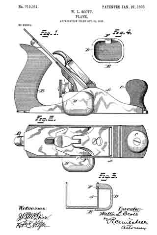
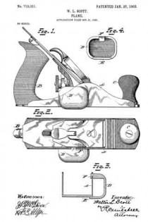
In the drawings, Figure 1 is a side elevation of a plane with the detachable handle applied thereto. Fig. 2 is a plan view. Fig. 3 is a cross-section of the plane-stock and detachable handle, as shown in Fig. 1. Fig. 4 is a view of the inside of the detachable handle.

A represents the stock of an iron plane. B is a handle permanently attached to the rear end thereof.

C is a front knob or handle, also usually permanently attached to the stock A. In ordinary use the operator grasps the two handles B C, The other details of the plane proper, such as the knife and the adjusting devices, it is unnecessary to describe in detail herein, because they constitute no part of this invention.

D is the body of a detachable handle, preferably in the form of a shell, since it provides a strong and light construction.

E is a lip on one side of the body D, the same being by preference of sufficient length to give a long flat bearing. Obviously the number of these lips E is immaterial. Two short lips spaced apart would give the same result. The lip E will for convenience of expression be termed herein the “fiat” lip. F is a hooked lip at the opposite side of the body D, the hook facing the flat lip E. Ordinarily the stock A of a metal plane is provided with cheek-pieces, one on each side, and these cheek-pieces are generally shaped as shown in Fig. 1, in which they incline upwardly from each end to a high point or crown.

In attaching the handle-body D the flat lip E is placed against the bottom of the plane-stock, and the handle is then pushed forward toward the highest part of the cheek-piece until the hooked lip F engages with it and may be wedged thereon, the hook of the lip F overstanding the upper edge of the cheek-piece and securing the handle in place on the side of the plane. The operator may then use the plane with one or both hands.

In case one hand is used the palm is placed against the rear side of the body D and the fingers are placed over the top of the plane, giving a secure grip. The position of the plane will then be on its side and the same may be pushed along the side or edge of the thing to be planed and the work done with ease and accuracy. In case the operator desires to use two hands he may grasp the solid handle B with one hand and the detachable handle D with the other, the latter taking the place of the knob-handle C. When the work is completed, the handle D may be easily removed by sliding the same backward and freeing the hook F from the cheek-piece of the stock.

Obviously the particular shape of the handle and its particular construction may be varied and modified in such ways as will suggest themselves to the mechanic skilled in the art without departure from the spirit and scope of this invention.

What I claim is —

1. A side handle for a plane comprising a body portion and means projecting from said body for detachably engaging the same at the side of a plane-stock.

2. A side handle for a plane comprising a body portion and means for frictionally engaging the same with the cheek-piece of the plane-stock.

3. A side handle for a plane comprising a body portion D, a flat lip on one side, and a lip on the opposite side said lips adapted to engage with the plane-stock.

4. A side handle for a plane comprising a body portion D, a flat lip at one edge thereof, and a hooked lip at the opposite edge thereof.

5. A side handle for a plane comprising a body portion, a lip on one edge thereof, a lip on the other side thereof, one of said lips being hooked.

Signed at San Francisco, California, this 10th day of October, 1902.

WALTER L. SCOTT.

Witnesses:
GEORGE PATTISON,
J. W. WRIGHT.

No. 464,701 – Plane Attachment (George H. Melendy) (1891)

[paiddownloads id=”480″]464701


UNITED STATES PATENT OFFICE.

_________________

GEORGE H. MELENDY, OF SAN FRANCISCO, CALIFORNIA,
ASSIGNOR OF ONE-HALF TO BENNETT BROTHERS, OF SAME PLACE.

PLANE ATTACHMENT.

_________________

SPECIFICATION forming part of Letters Patent No. 464,701, dated December 8, 1891.
Application filed January 14, 1891. Serial No. 377,761. (No model.)

_________________

To all whom it may concern:

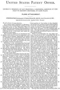
Be it known that I, GEORGE H. MELENDY, a citizen of the United States, residing in the city and county of San Francisco, State of California, have invented an Improvement in Plane Attachments; and I hereby declare the following to be a full, clear, and exact description of the same.

My invention relates to an attachment for planes such as are in use by carpenters and others; and it consists, essentially, of means for adjusting and compensating the throat to the wear which takes place upon the bottom face of the plane by constant use, and in certain details of construction.

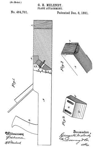
Referring to the accompanying drawings for a more complete explanation of my invention, Figure 1 is a longitudinal vertical section taken through the front of the plane showing the adjustment thereof. Fig. 2 is a view showing the throat-adjusting block removed. Fig. 3 is a perspective view of the front end of my plane.

A is the body of the plane having the handle B and the open throat C within which the plane-iron is fixed in any usual or suitable manner. When these plane~bodies are made of wood, they are subjected to considerable wear by reason of the friction of the lower face with the surface over which they are moved and which the plane-iron is intended to cut and dress, and as this wear takes place the throat for the escape of the shavings loses its proper proportion, thus necessitating some adjustment if the plane is to have any further use. In my invention I have shown the throat having an inclined chamber D made in the forward portion of it by inserting a piece E, a portion of the under surface of which is inclined and projects into the throat and forms the top wall of the inclined chamber, this chamber inclining into the forward portion of the body A. This piece E, which forms the chamber D, is designed to protect the adjustable block F and moving parts from dust or shavings, and it is important for the reason that without it they would become choked and clogged. Within this chamber below the block E is fitted a block F, the front portion of which rests upon the front portion of the incline in the chamber D, and the rear portion is made with two faces G and G’, meeting each other at an angle, as shown, the face G’ being approximately vertical when the plane is in its ordinary position. Through the upper portion of this block slots are made and screws H serve to fix it at any desired point.

When by considerable use the plane has been worn down, it will be manifest that by reason of the inclined rear face of the opening C upon which the plane-iron is supported the throat will become enlarged and will not be in proper shape for the best work. When this occurs, the screws or fastening of the movable throat-piece are loosened, and this piece is allowed to move downward, sliding upon the inclined surface of the front of the chamber, and this forces the surface G’ of the movable block nearer to the edge of the plane-iron. The block is moved downward until the throat is made of the proper size, when it is again secured in place. The lower end of the block which would be projected beyond the surface of the plane by this movement is cut off so that it is again flush with the surface of the plane. By this device the throat of the plane may be adjusted and retained at the proper size until the plane is entirely worn out. In connection with this device I have shown the inserted block I, having a rounded or convex surface, fitted into a channel or groove of semicircular form in cross-section, which is formed vertically in the front end of the plane. This block is secured in the channel with the grain of the wood extending vertically, so that the end grain is exposed at the bottom and flush with the surface of the plane. The object of this is to equalize the wear upon the plane, as it is well known that the front end of the plane which is first pushed over the rough surfaces of the work to be planed is worn and rounded off more rapidly than the other portions which are situated behind the plane-iron, and by reason of this hard inserted piece and the fact that the wear comes upon the end of the grain the wear will be equalized and the plane kept in proper condition much longer.

Having thus described my invention, what I claim as new, and desire to secure by Letters Patent, is —

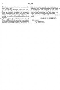
1. In a plane having a plane-iron and a throat, a piece E, let into the throat so as to form an inclined chamber, an adjustable block in said chamber below the piece E, and screws passing through and adjustably securing the block, substantially as herein described.

2. In a plane, the body thereof having its front end formed with a vertical groove semi-circular in cross-section, and a piece having a convex rear surface fitting the groove so that its lower end is flush with the bottom of the plane, said inserted piece having its grain at right angles with the grain of the body, whereby it presents an end grain surface at the bottom to equalize the wear upon the plane, substantially as herein described.

In witness whereof I have hereunto set my hand.

GEORGE H. MELENDY

Witnesses:
A. B. MERRILL,
J. W. RICHARDS.

No. 240,076 – Spokeshave (Louis Bauer) (1881)

[paiddownloads id=”312″]240076


UNITED STATES PATENT OFFICE.

_________________

LOUIS BAUER, OF SAN FRANCISCO, CALIFORNIA.

SPOKESHAVE.

_________________

SPECIFICATION forming part of Letters Patent No. 240,076, dated April 12, 1881.
Application filed December 27, 1880. (No model.)

_________________

To all whom it may concern:

Be it known that I, LOUIS BAUER, of the city and county of San Francisco, State of California, have invented an Improved Spoke-shave; and I hereby declare the following to be a full, clear, and exact description thereof.

My invention relates to certain improvements in tools for working wood, leather, and other materials, these tools being known as “spokeshaves.”

My invention consists in a novel method of holding and clamping the blade of the shave in place between two clamping-jaws, so that any style of blade may be held in place and may be adjusted to or from the plate or edge, which serves as a gage.

My invention further consists in a means for setting the blade to or from the gage-plate, so as to regulate the cut, all of which will be more fully explained by reference to the accompanying drawings, in which —

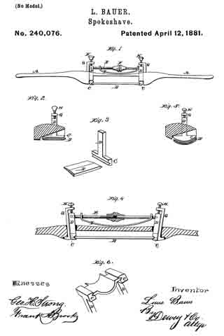
Figure 1 is a view of my tool. Fig. 2 is a transverse section. Fig. 3 is a detail view of the knife and holding-post. Fig. 4 is a longitudinal section. Figs. 5 and 6 are modifications of the cutter.

A is the handle or stock of my tool. This handle may be like the ordinary spokeshave, with two ends, or it may be carried back as a single handle, by which to draw or push the tool. It is fitted in the usual manner near the center, to admit the cutting-blade B.

In the ordinary construction of these tools the blade has two ends or tangs turned up and fitted to enter holes made transversely through the stock.

In my invention the blade B has its ends straight and made with wedge or other shaped edges, so as to be held firmly between suitable jaws, C. These jaws are formed upon the ends of posts D, which extend up through the stock A just at the ends of the cutter or blade.

These posts have their fulcrums in the stock, either by being pivoted in the slot, or they may simply be made a little smaller than the holes through which they pass, so that they may have a side movement or oscillation. Between the upper ends of these posts a bar, E, extends, this bar being formed in two parts with a screw-thread upon one or both, so that by means of a nut, F, in the center it may be lengthened or shortened. When the bar is made longer by turning the nut it forces the upper ends of the posts D apart, thus drawing the lower ends with their jaws together, and clamping the cutter-blade firmly between them. In the present case I have shown one part of the bar E made angular or pinned to one post, so as not to turn. This part has screw-threads upon it, while the other part has a nut to fit these threads, its opposite end turning loosely in its post. By this method of securing the cutter in place it may always be adjusted to or from the gage-plate and its proper distance maintained until it is entirely worn out.

It will be seen that any form of cutting-blade may be secured in this manner, the grooves in the bottom of the posts which receive the ends of the blade being straight or curved, as required.

The distance of the cutter from the stock may be regulated to make a thicker or thinner out by loosening the bar E and moving the posts up or down; but for delicate adjustment I employ a device constructed as follows:

G are posts which pass through the stock behind the posts D, and have their lower ends turned outward, or otherwise secured. Their upper ends are turned at right angles above the posts D, and screws H pass through them, so as to press upon the heads of the posts D. When these screws are turned in one direction they will force the posts D downward and move the blade or cutter away from the stock, thus leaving a wide slot. In order to return the blade and make the slot narrower the screws may be so connected with the posts D as to draw them back; but I have shown a flat curved spring, I, the ends of which are turned up and perforated, so that they slip over the ends of the bar E. The center of the spring presses upon the stock, and when the screws H are turned back the spring will force the posts D and bar E upward, thus drawing the knife or cutter closer to the stock. After the adjustment has been made satisfactorily, the bar E, which was previously loosened, may be again tightened, so as to hold the cutter in place.

The construction here described enables me to use a single stock for a number of cutters, and they maybe worn down to a narrow blade before being cast aside.

This tool is especially valuable for working leather, on account of its delicate and easy adjustment.

Having thus described my invention, what I claim as new, and desire to secure by Letters Patent, is —

1. The stock constructed with the inner curved faces, in combination with the blade or cutter B, having its ends beveled to fit corresponding grooves in the lower ends of the oscillating posts D, said posts having the straining rod or bar E extending between their upper ends, and provided with a nut, F, whereby the cutter may be clamped or released, substantially as herein described.

2. The oscillating posts D, with their straining-bar E fitted to hold the cutter B, as shown, in combination with the posts G, screws H, and spring I, whereby the cutter may be adjusted to or from the stock, substantially as herein described.

In witness whereof I have hereunto set my hand.

LOUIS BAUER.

Witnesses:
S. H. NOURSE,
FRANK A. BROOKS.

No. 146,004 – Improvement In Combination-Planes (Andrew Johnson) (1873)

[paiddownloads id=”223″]146004


UNITED STATES PATENT OFFICE.

_________________

ANDREW JOHNSON, OF SAN FRANCISCO, CALIFORNIA.

IMPROVEMENT IN COMBINATION-PLANES.

_________________

Specification forming part of Letters Patent No. 146,004, dated December 30, 1873; application filed November 15,1873.

_________________

To all whom it may concern:

Be it known that I, ANDREW JOHNSON, of San Francisco city and county, State of California, have invented a Combination-Plane; and I do hereby declare the following description and accompanying drawings are sufficient to enable any person skilled in the art or science to which it most nearly appertains to make and use my said invention without further invention or experiment.

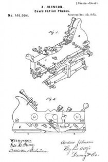
The object of my invention is to provide an improved combination-plane, the novelty of which consists, mainly, in the use of a series of adjustable guides and gages by which the tool may be made to out in straight lines or upon the concave or convex surfaces of the work, whether such surfaces lie in the line of the tool or at right angles with it. My invention further relates to the employment of a series of cutting-irons which may be so combined as to cut any desired form of molding.

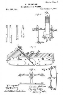
Referring to the accompanying drawings for a more complete explanation of my invention, Figure 1, Sheet 1, is a perspective view of my plane. Fig. 2 is a side elevation. Fig. 3, Sheet 2, is a back view. Fig. 4, Sheet 2, is a sectional elevation. Figs. 5 and 6 are detailed views of the gage.

A is the body of the plane or the block, and it is made short, so as to facilitate its use on short curves. From its lower face project the plates B, one in front and one behind the cutter, and which serve as a guide for the plow and as a back for the cutting-iron. These plates are secured by set-screws, C, which pass horizontally through slots in them and enter the projecting lower part of the block A. The plates are so formed that a thin elastic strip of metal, c, extends on each from near the cutter forward and backward respectively to the front and rear of the block, where they are turned up and have a horizontal portion, d, which is slotted to receive a set-screw, e, which secures it to the vertically-adiusting standard I. A wide open space intervenes between the part B of the plates and the strip c. The strip unites with the plate at the end nearest the cutters, but is free at the opposite end, so that it can be adjusted up and down when the tool is to be used upon concave or convex surfaces in a vertical plane.

If the tool is to be used around concave or convex surfaces which lie in a horizontal plane, the set-screws e are loosened, and the elastic strip c is curved either to or from the block, as the case may be, and secured by the screws.

The guide and gage for this work consist of a plate, F, which has its center riveted to a projection, G, on the bar H, while its ends are connected with the ends of the bar by slotted links V, so that this plate F can be bent from side to side to correspond with the curve given to the strip c, and secured by set-screws, as shown. The bar H has a vertical post, J, extending upward, and this post is slotted to receive a set-screw, K, which secures it to the bar L. This bar L is connected at each end to the block A by long screws M, which have double nuts N N, between which the bar L is held, or smooth bars may be used instead of screws M with a set-screw. By means of these nuts the distance of the guide-plate F from the tool is regulated, while its vertical adjustment is made by means of the screw K and the slotted standard or post J.

In order to cut a variety of moldings with the same tool, I provide a number of cutters, n, of various shapes. The cutters have any suitable number of supporting-backs o, which have screws p passing through them, and provided with double nuts, so that the back plates can be adjusted to suit the number or kind of cutters. These plates and their equivalent guides o’ before the cutters may be cut away, as shown, so as to allow the tool to work freely on curves, either vertical or horizontal, and can be adjusted by the nuts to the highest point of the cutting-iron from the main face-plate. The lower ends of the cutters are supported by the back plates, and the upper ends are suitably connected with the setting-screw, so that any number of cutters can be easily adjusted at any time. In the present case I have shown a plate, R, which slides upon the inclined front of the handle s. This plate has two projections or lugs, t t, near its lower end, and upon these projections the holes or slots in the upper ends of the cutters are fitted. By the variation allowed by the slots each iron can be set separately. The plate B has a nut, x, formed at its upper end, and a screw, y, passes through this nut, and serves to operate the plate and move it up or down, as may be desired, to give the cutters the proper set. The cutters being placed, their upper ends will be held as described by the lugs t, while the lower ends are steadied by the back plates o. A plate, z, is fitted to press the cutters against these plates o, being operated by a screw, g, and this holds them firmly to their work, and causes them all to work as one tool. Gages h h, with set-screws, serve to regulate the depth of cut to be made, and the distance of the cut from any particular point or surface is regulated by means of the sliding bars m. The spring-gage can be adjusted up or down to facilitate the working of a molding upon the edge of a raised panel or a flat or plain surface.

It will be manifest that any number of wooden faces, Q, with either hollows, round, or flat surfaces can be made to fit the various combinations of cutters, and which may be substituted for or placed between the plates o, if desired, for straight work. The plate B, together with the blocks or faces Q, when used in place of the metal plates, serve to form a match-plane, the irons n, being employed with them.

Having thus described my invention, what I claim, and desire to secure by Letters Patent, is —

1. The plates B, having elastic adjustable curving strip c, combined with the block A and adjusting-standards I, substantially as and for the purpose described.

2. The combination of the elastic gage-plate F, bar H, and slotted links V with their set-screws.

3. In combination with the elastic adjustable gage-plate F, the vertically-sliding post J with its holding-screw, and the bar L with its horizontally-adjusting screws M, and the nuts N, substantially as and for the purpose herein described.

4. The adjustable curved plates o o’, in combination with plate B and intermediate blocks Q, substantially as and for the purpose set forth.

In Witness whereof I hereunto set my hand and seal.

ANDREW JOHNSON.

Witnesses:
GEO. H. STRONG,
C. MILTON RICHARDSON.

No. 107,653 – Improvement In Tools For Cutting Wood-Moldings (Charles E. Boynton) (1870)

[paiddownloads id=”142″]107653


United States Patent Office.


CHARLES E. BOYNTON, OF SAN FRANCISCO, CALIFORNIA, ASSIGNOR TO
HIMSELF AND ISAAC N. VOSBURG, OF SAME PLACE.

Letters Patent No. 107,653, dated September 27, 1870.
_________________

IMPROVEMENT IN TOOLS FOR CUTTING WOOD-MOLDINGS.

_________________

The Schedule referred to in these Letters Patent and making part of the same.

_________________

To all whom it may concern:

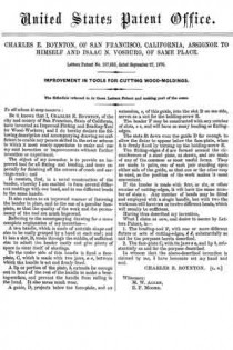
Be it known that I, CHARLES E. BOYNTON, of the city and county of San Francisco, State of California, have invented an Improved Fluting and Beading-Tool for Wood-Workers; and I do hereby declare the following description and accompanying drawing are sufflcient to enable any person skilled in the art or science to which it most nearly appertains to make and use my said invention or improvements without further invention or experiment.

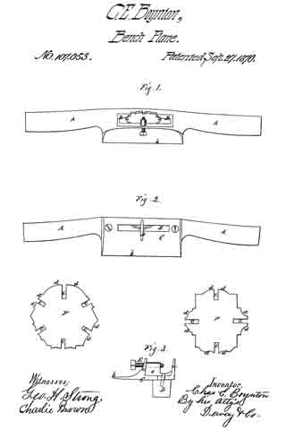
The object of my invention is to provide an improved tool for all fluting and beading, and more especially for finishing off the corners of coach and carriage-work; and

It consists, first, in a novel construction of the beader, whereby I am enabled to form several different moldings with one bead, and to use different beads in the same handle.

It also relates to an improved manner of fastening the bender in place, and to the use of a peculiar face-plate, so that the quality of the work and the permanency of the tool are much improved.

Referring to the accompanying drawing for a more complete explanation of my invention —

A is a handle, which is made of suitable shape and size to be easily grasped by a hand at each end; and it has a slot, B, made through the middle, of sufficient size to admit the header easily and give plenty of space to clear itself of shavings.

To the under side of this handle is fixed a face-plate, C, which is made with two jaws, a a, between which the handle is set and firmly fixed.

A lip or portion of the plate, D, extends far enough out in front of the rest of the handle to make a bearing-surface, and prevent the handle from rolling in the hand. It also saves much wear.

A guide, D, projects below the face-plate, and an extension, e, of this guide, into the slot B on one side, serves as a nut for the holding-screw E.

The beader F may he constructed with any number of slots, c c, and will have as many beading or fluting-edges.

The slots fit down over the guide D far enough to allow the fluter to appear below the face-plate, when it is firmly fixed by turning up the holding-screw E.

The fluting-edges d d are formed around the circumference of a steel plate, as shown, and are made of any of the common or most useful forms. They are made in pairs, one of each pair standing upon either side of the guide, so that one or the other may be used, as the position of the work makes it most convenient.

If the beader is made with four, or six, or other number of cutting-edges, it will have the same number of slots c. Any number of beads may be fitted and employed with a single handle, but with two the workman will have ten or twelve different beads, which will usually be sufficient.

Having thus described my invention, What I claim as new, and desire to secure by Letters Patent, is —

1. The beading-tool F, with one or more different fluters or sets of cutting-edges, d d, substantially as and for the purposes herein described.

2. The face-plate C, with its jaws a a, and lip b, substantially as and for the purpose described.

In witness that the above-deseribed invention is claimed by me, I have hereunto set my hand and seal.

CHARLES E. BOYNTON. [L. S.]

Witnesses:
M. W. ALLEN,
E. F. MOORE.

No. 50,378 – Improvement In Bench Planes (George Müllear) (1865)

[paiddownloads id=”107″]50378


UNITED STATES PATENT OFFICE.

_________________

GEORGE MÜLLEAR, OF SAN FRANCISCO, CALIFORNIA.

IMPROVEMENT IN BENCH-PLANES.

_________________

Specification forming part of Letters Patent No. 50,378, dated October 10, 1865.

_________________

To all whom it may concern:

Be it known that I, GEORGE MÜLLEAR, of the city and county of San Francisco, and State of California, have invented certain new and useful Improvements in Carpenters’ Planes; and I do hereby declare that the following description and accompanying drawings are sufficient to enable any person skilled in the art or science to which it most nearly appertains to make and use my said invention or improvements without further invention or experiment.

The nature of my invention and improvement in planes consists in clamping the cutting-bit and turning the shaving cut by means of a metal cap drawn against the bit by a screw in the rear cf the plane-stock, and in making the clamping-cap adjustable horizontally by means of brackets, grooves, and adjusting-screws.

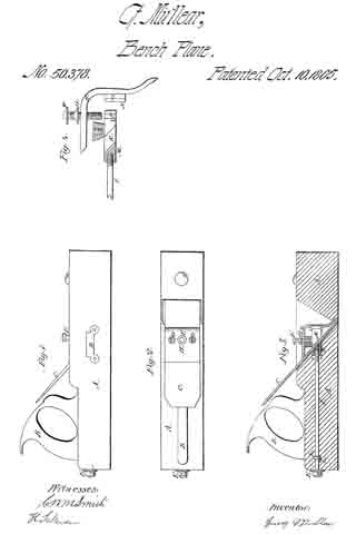
In the accompanying drawings, Figure I is an elevation of a plane with my improvements. Fig. 2 is a plan or top view. Fig. 3 is a section of the plane cut perpendicularly length-wise. Fig. 4 shows some of the parts enlarged and separate from the stock.

In these drawings, A is the plane-stock, B the handle, and C the cutting-bit, all of which are made in the form in common use by mechanics.

A mortise is made entirely through the stock horizontally for the traversing block M, which is fitted to traverse in it and moved by the screw I, which extends back through the rear of the stock and is provided with a collar, K, and there is a pin, L, through the stock behind the collar to prevent the screw from corning out when it is turned to traverse the block M. This block M is provided with two arms, R, which extend forward each side of the bit C and are perforated for screws which screw through the arms into the block N, which is properly the front part of the block M, as they are both traversed together by the screw I. The block N has two perpendicular grooves, P, for the flanges S of the brackets O on the cap H to traversein when the cap H is raised by the screw F or drawn down by the screws G G, which pass through the cap and screw into the block N, the screw F screwing through the cap onto the block N, and the screws G G passing through the cap and screwing into the block N, so that by turning the screws the cap may be adjusted higher or lower on the bit. The cap H is made in the form shown in Figs. 3 and 4, and bent so that both ends bear or press upon the bit C to clamp it in the stock and hold it in its place while the plane is used.

The head E of the screw I fits against the end ofthe stock A, so that by turning the screw I the blocks M and N, with the cap H, are drawn back toward the rear of the plane and the cap H presses upon the bit C and clamps it fast and holds it in position upon its bed in the stock while the plane is used; and the loweredge ofthe cap H may be adjusted higher or lower on the bit by turning the screws F and G so as to turn the shavings cut by the bit more or less short as they are cut. There is a brass plate, D, fitted into each side cf the plane and fastened by screws to cover the mortise occupied by the block M in the stock.

I contemplate that the traversing blocks M and N may both be made in one piece of malIeable iron, if preferred that way.

Having described my improvements, I claim —

I. The screw I, traversing blocks M and N, and cap H, for clamping and holding the bit and turning the shaving cut, substantially as described, whether the cap is made adjustable horizontally or otherwise.

2. Making the cap H adjustable higher or lower onthe cutting-bit by means of the brackets O, grooves P, and screws F and G G.

GEORGE MÜLLEAR.

Witnesses:
C. W. M. SMITH,
H. SAKEMAN.