
| PLEASE NOTE: The images presented on this page are of low resolution and, as a result, will not print out very well. If you wish to have higher resolution files then you may purchase them for only $2.95 per patent by using the "Buy Now" button below. All purchases are via PayPal. These files have all been cleaned up and digitally enhanced and are therefore suitable for printing, publication or framing. Each zip package contains all the images below (some packages may contain more), and purchased files can be downloaded immediately. |
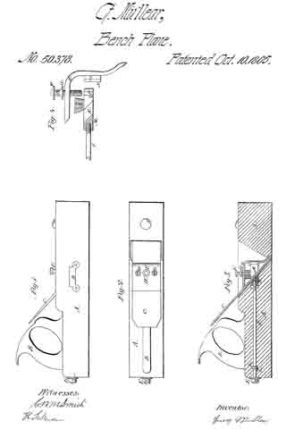
UNITED STATES PATENT OFFICE.
_________________
GEORGE MÜLLEAR, OF SAN FRANCISCO, CALIFORNIA.
IMPROVEMENT IN BENCH-PLANES.
_________________
Specification forming part of Letters Patent No. 50,378, dated October 10, 1865.
_________________
To all whom it may concern:
Be it known that I, GEORGE MÜLLEAR, of the city and county of San Francisco, and State of California, have invented certain new and useful Improvements in Carpenters’ Planes; and I do hereby declare that the following description and accompanying drawings are sufficient to enable any person skilled in the art or science to which it most nearly appertains to make and use my said invention or improvements without further invention or experiment.
The nature of my invention and improvement in planes consists in clamping the cutting-bit and turning the shaving cut by means of a metal cap drawn against the bit by a screw in the rear cf the plane-stock, and in making the clamping-cap adjustable horizontally by means of brackets, grooves, and adjusting-screws.
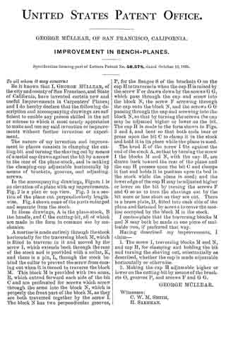
In the accompanying drawings, Figure I is an elevation of a plane with my improvements. Fig. 2 is a plan or top view. Fig. 3 is a section of the plane cut perpendicularly length-wise. Fig. 4 shows some of the parts enlarged and separate from the stock.
In these drawings, A is the plane-stock, B the handle, and C the cutting-bit, all of which are made in the form in common use by mechanics.
A mortise is made entirely through the stock horizontally for the traversing block M, which is fitted to traverse in it and moved by the screw I, which extends back through the rear of the stock and is provided with a collar, K, and there is a pin, L, through the stock behind the collar to prevent the screw from corning out when it is turned to traverse the block M. This block M is provided with two arms, R, which extend forward each side of the bit C and are perforated for screws which screw through the arms into the block N, which is properly the front part of the block M, as they are both traversed together by the screw I. The block N has two perpendicular grooves, P, for the flanges S of the brackets O on the cap H to traversein when the cap H is raised by the screw F or drawn down by the screws G G, which pass through the cap and screw into the block N, the screw F screwing through the cap onto the block N, and the screws G G passing through the cap and screwing into the block N, so that by turning the screws the cap may be adjusted higher or lower on the bit. The cap H is made in the form shown in Figs. 3 and 4, and bent so that both ends bear or press upon the bit C to clamp it in the stock and hold it in its place while the plane is used.
The head E of the screw I fits against the end ofthe stock A, so that by turning the screw I the blocks M and N, with the cap H, are drawn back toward the rear of the plane and the cap H presses upon the bit C and clamps it fast and holds it in position upon its bed in the stock while the plane is used; and the loweredge ofthe cap H may be adjusted higher or lower on the bit by turning the screws F and G so as to turn the shavings cut by the bit more or less short as they are cut. There is a brass plate, D, fitted into each side cf the plane and fastened by screws to cover the mortise occupied by the block M in the stock.
I contemplate that the traversing blocks M and N may both be made in one piece of malIeable iron, if preferred that way.
Having described my improvements, I claim —
I. The screw I, traversing blocks M and N, and cap H, for clamping and holding the bit and turning the shaving cut, substantially as described, whether the cap is made adjustable horizontally or otherwise.
2. Making the cap H adjustable higher or lower onthe cutting-bit by means of the brackets O, grooves P, and screws F and G G.
GEORGE MÜLLEAR.
Witnesses:
C. W. M. SMITH,
H. SAKEMAN.