
| PLEASE NOTE: The images presented on this page are of low resolution and, as a result, will not print out very well. If you wish to have higher resolution files then you may purchase them for only $2.95 per patent by using the "Buy Now" button below. All purchases are via PayPal. These files have all been cleaned up and digitally enhanced and are therefore suitable for printing, publication or framing. Each zip package contains all the images below (some packages may contain more), and purchased files can be downloaded immediately. |
UNITED STATES PATENT OFFICE.
_________________
LYMAN C. BLISS, OF RICHMOND, INDIANA, ASSIGNOR. TO LYMAN C. BLISS AND JOHN GRIFFITH.
IMPROVEMENT IN BENCH-PLANES.
_________________
Specification forming part of Letters Patent No. 50,530, dated October 17, 1865.
_________________
To all whom it may concern:
Be it known that I, LYMAN C. BLISS, of Richmond, in the county of Wayne and State of Indiana,have made new and useful Improvements in Bench-Planes; and I do hereby declare the following to be a full, clear, and exact description of the nature, construction, and operation of the same, sufficient to enable one skilled in the art to which it appertains to construct and use the same, reference being had to the accompanying drawings, which are made part of this specification, and in which —
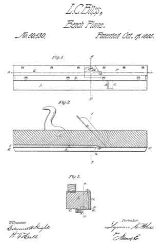
Figure 1 is a View of the under side or face of the plane. Fig. 2 is a longitudinal vertical section on the line x x, Figs. 1 and 3. Fig. 3 is a transverse vertical section on the line y y, Figs. 1 and 2.
The same letters refer to corresponding parts in the different figures.
The invention consists in the adaptation to and arrangement in the tool of the jointer and slat-cutting plane.
A is the stock ofthe plane; and B,a strip which is fastened to the face of the plane, acting as a guide and separating the bits., The side C of the plane is occupied by the jointing-bit D, of ordinary construction, and the other side of the plane is faced with plates E and F, the former of which passes from the hind end of the plane to the back edge of the bit G, while the other, starting from the forward end of the plane, is partially overlapped by the oblique edge of the plane-bit G. The bit G is secured by means of a bolt, H, which passes through the slot in the rear edge of the bit and also through an orifice in the plate F, which on its rear edge is divided. The portion f of the plate, or that immediately over the longitudinal channel I in the face of the plane-stock, is cut diagonally, so as to present a yielding edge parallel with the cutting-edge of the bit, which overlaps it.
The operation is as follows: The jointing-bit D being first brought into action, the board from which the strip, splint, or slat is to be cut is straightened, when the plane is shifted so as to bring the other side into action, the sliver cut by the bit G pressing back the tongue f of the plate F, and passing out by the way of the channel I, to be discharged at the rear end ofthe plane. The splint or slat being separated from the edge of the board by the draw-cut of the bit G, leaves the said splint smoother and without cracks.
Having described my invention, what I claim therein as new, and desire to secure by Letters Patent, is —
As an article of manufacture, a bench-plane constructed, as described, with a jointing-bit and a draw-cut splint-cutting bit on the opposite sides of the dividing-strip on the face of the plane.
LYMAN O. BLISS.
Witnesses :
JOHN FINLEY,
THOS. A. DUGDALE.