
| PLEASE NOTE: The images presented on this page are of low resolution and, as a result, will not print out very well. If you wish to have higher resolution files then you may purchase them for only $2.95 per patent by using the "Buy Now" button below. All purchases are via PayPal. These files have all been cleaned up and digitally enhanced and are therefore suitable for printing, publication or framing. Each zip package contains all the images below (some packages may contain more), and purchased files can be downloaded immediately. |

UNITED STATES PATENT OFFICE.
_________________
HARRISON OGBORN, OF RICHMOND, INDIANA.
IMPROVEMENT IN SPLINT-PLANES.
_________________
Specification forming part of Letters Patent No. 50,947, dated November 14, 1865.
_________________
To all whom it may concern:
Be it known that I, HARRISON OGBORN, of Richmond, in the county of Wayne and State of Indiana, have invented certain new and useful Improvements in Planes for Cutting Blind-Slats, Splints for Baskets, and other similar work; and I do hereby declare that the following is a full, clear, and exact description of the construction and operation of the same, reference being had to the annexed drawings, made a part of this specidcation, and the letters of reference thereon, the same letters referring to identical parts.
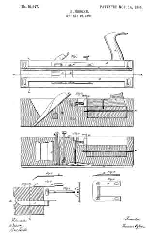
Figure 1 is a side view of the plane when arranged for use as a jack-plane, showing the bottom of the plane used for cutting slats, &c.
Fig. 2 is a longitudinal vertical section of the plane through the line y y, Fig. 4. Fig. 3 is a like section through the line x x, Fig. 4. Fig. 4 is a transverse section of the stock. Fig. 5 is a view of the knife employed for splitting the slats or splints. Fig. 6 is a view of a knife for splitting the slats with beveled edges. Fig. 7 shows the adjustable plate for determining the cut and removing splinters that wedge in the plane. Fig. 8 is a sectional view of the knife or bit used on the splint-plane. Fig. 9 is a top view of the same.
The stock of the plane A is arranged for two bits, and having two faces. One of these is an ordinary jack-plane, as shown in Figs. 1 and 2.
The handle B is adjustable, and may be made to stand perpendicularly to either of the plane-faces. It turns upon a rod, M, and, swinging in a notched recess in the corner of the stock, is held perpendicularly to either face by an ordinary window-catch, of which there are two shown, Figs. 2 and 3, G G’.
On the bottom of the face of the splint-plane are shown two adjustable guides, one square, the other beveled. One of these, according to the character of the work, is used on the left-hand side of the plane, held in place by screws with oblong heads working in slots in the ends of the guides, as shown in Fig. 1.
D is the knife or bit ofthe splint-plane, held in place by the same kind of screws working in slots, so as to allow the adjustment of the knife by the aid of the set-screws N N.
E shows the bit of the jack-plane, of ordinary construction, and arranged in the usual manner.
K is an adjustable plate, held by similar screws on the face, allowing its adjustment to the knife as they are worn away in use, to which is attached the set-screw passing through the stock and working in a collar on the upper surface of the plane. This arrangement makes it easy to withdraw the plate in case a splinter should wedge in the space between the plate and knife.
The knives H I, one straight, the other bent for cutting beveled edges, work as shown in Figs. 3 and 4. The knives are held in place by the wedge L, and the points protrude through narrow slots in the plate K. (Shown in Fig. 1.) The bent knife its the beveled point of the wedge L. When the straight knife is used the wedge goes on the right of it, but on the left side of the bent knife. There are one or more of these knives used, according to the number of slats intended to be cut from the board. The bent knife is used with the beveled guide.
In operating with this plane, the boards, being dressed, are cut into narrow strips of the proper width on their edges by the knife H, or so that the slats shall have beveled edges, by the knife I. The splints are cut by the knife or bit D passing between the plate K and the bit D. Rising over D, they are bent in a contrary direction, and passing out under the lower surface of the plane they are flattened and delivered free from curves or tendency to twist.
Having thus fully explained the character and operation of my improvements, what I claim as my invention, and seek to secure by Letters Patent, is —
1. The arrangement, in a splint-plane, of the plate K, bit D, and one or more splitting-knives, and guide C, all constructed and combined substantially as and for the purpose set forth.
2. The arrangement, in a splint-plane, of the piate K, bit D, beveled guide C and one or more bent knives, I, all constructed and combined substantially as and for the purposes set forth.
3. The combination of the plane-stock A and adjustable handle B, so constructed with the rod M and springs G and G’ as to be capable of being arranged perpendicularly to the two faces of the plane, substantially as described. In testimony whereof I have signed my name to this specifcation in the presence of two subscribing witnesses.
HARRISON OGBORN
Witnesses:
R. MASON, BEN FIELD.