
| PLEASE NOTE: The images presented on this page are of low resolution and, as a result, will not print out very well. If you wish to have higher resolution files then you may purchase them for only $2.95 per patent by using the "Buy Now" button below. All purchases are via PayPal. These files have all been cleaned up and digitally enhanced and are therefore suitable for printing, publication or framing. Each zip package contains all the images below (some packages may contain more), and purchased files can be downloaded immediately. |
UNITED STATES PATENT OFFICE.
_________________
JAMES DEMPSEY, OF RICHMOND, INDIANA.
IMPROVEMENT IN SPLINT-PLANES.
_________________
Specification forming part of Letters Patent No. 51,153, dated November 28, 1865.
_________________
To all whom it may concern:
Be it known that I, JAMES DEMPSEY, of Richmond, in the county of Wayne and State of Indiana, have invented certain new and useful Improvements in Planes for Cutting Slats for Window-Shades or other Thin Splints of Wood.
The object of my invention is to construct a splint-plane that shall be as readily adjustable as the ordinary hand-plane, and have such a channel for the splint when out as that it shall not be broken by being thrown abruptly upward over the knife. In other planes either the splint is liable to be broken or the knife placed horizontally is ditiicult of adjustment. Another object is to provide that the splint when cut shall be perfectly smooth and fit for use as it comes from the plane. Both of these objects are, I believe, accomplished by my im-provements.
To enable others skilled in the art to make and use my invention, I will describe its construction and operation, reference being had to the annexed drawings, making a part of this specification, and the lettering thereon.
In the different plans the same letters refer to identical parts.
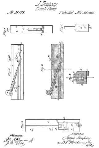
Figure 1 is an elevation showing the half of the plane when divided into two parts, on the line x x, Fig. 3, where the plane as constructed is divided. Fig. 2 is a longitudinal section on the line x x, Fig. 3. Fig. 3 is a transverse section upon the line y y, Fig. 4. Fig. 4 is a plan of the plane, showing the bottom part, the guide being represented as cut away in part. Fig. 5 is a plan showing the construction of the bit. Fig. 6 is a plan showing the construction of the spring in the bottom of the plane.
The stock is made in two parts, A and B, of wood, joined by the dowel-pins L L and by screws.
C is the bit, of which about two inches of the lower end is nearly horizontal, but depressed at the point sutliciently to give the cutting-edge the requisite draft into the wood. It is bent at N, rising and passing transversely through the stock. It is adjusted by the set-screw H, and held firmly in place by the wedge M and clamps E E. These clamps catch upon the bit below and hold it firmly by stress of the nuts E’ E’ upon their upper ends. This bit is constructed with the rectangular slot G, which opens from the angle and extends upward about three inches, and having a width of about seven-eighths (7/8) of an inch. Over this slot the spring G is placed, bent upward and having the upper extremity, near O, turned slightly down, so as to hold firmly to the splint as it passes, and yet guide it through the slot at O. Upon the bottom of the plane, attached by a set-screw working in the slot F, is the spring D, the tongue extending above the bit and forming a guide for the splints as cut. On the bottom of the side B of the stock is fastened a guide, P, made adjustable by the set-screws and slots K.
On the under side ofthe wedge M, at its lower extremity, is cut a groove, of the width of the slot in the bit C, and terminating a little above the point ofthe spring G. Through this groove passes the splint.
In operating with the plane the guide p is set at one-half the width of the splint to be cut from the line x x. The bit C and spring D being adjusted by the set-screws I and H to cut splints of the required thickness, the bit C is held firmly in place by the wedge M and clamps E. The splint, being cut by the sharp point of the bit, rises above it, passing under the tongue of the spring upward through the groove in the under side of the wedge M, over the spring G. It passes through the bit C at O, and is carried through the stock in the groove D, passing out behind the plane unbroken and highly polished by the combined action of the cutter-bit and spring.
Having fully explained my mode of constructing and operating splint-planes, what I claim as my invention, and seek to secure by Letters Patent, is —
1. Constructing the bit C of a splint-plane with the slot and spring, substantially as described.
2. The arrangement of the spring D, clamps E, wedge M, stock A B, with the bit C, all of them constructed and combined substantially as and for the purpose described.
In testimony whereof I have signed my name to this specification in the presence of two subscribing witnesses.
JAMES DEMPSEY.
Witnesses:
R. MASON,
JOHN S. HOLLINGSHEAD.