No. 752,365 – Spokeshave (John H. Spear) (1904)

[paiddownloads id=”599″]752365


UNITED STATES PATENT OFFICE.

_________________

JOHN H. SPEAR, OF SPRINGFIELD, MASSACHUSETTS.

SPOKESHAVE.

_________________

SPECIFICATION forming part of Letters Patent No. 752,365, dated February 16, 1904.
Application filed August 21, 1903. Serial No. 170,298. (No model.)

_________________

To all whom it may concern:

Be it known that I, JOHN H. SPEAR, a citizen of the United States of America, and a resident of Springheld, in the county of Hampden and State of Massachusetts, have invented certain new and useful Improvements in Spoke-shaves, of which the following is a full, clear, and exact description.

This invention relates to improvements in spokeshaves, and more particularly pertains to the means for securing the adjustment convenintly of the blade or knife so that it will cut a fine or thick shaving, as desired, and for confining the knife when adjusted.

The invention consists in a spokeshave constructed substantially as shown in the accompanying drawings and as set forth in the claims.

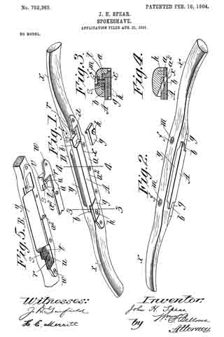
In the drawings, Figure 1 is a perspective view of the improved spokeshave as seen at its under or shaving side. Fig. 2 is a perspective view of the same as seen looking at the back and top thereof. Fig. 3 is a cross-sectional view as taken on the line 3 3, Fig.1. Fig. 4 is a cross-sectional view as taken on the line 4 4, Fig. 1. Fig. 5 is a perspective view of the under side of the stock or body of the spokeshave, showing also a metallic fitting therefor, a right-hand half of the latter being indicated as broken away and removed from its place of application on, and within, the stock, which is shown recessed for the reception thereof.

Similar characters of reference indicate corresponding parts in all of the views.

Referring to the drawings, A represents the knife or blade, and B the body or stock, having handles x x at its opposite ends, as usual, the said stock being intermediately provided with the usual throat-forming recess y and has a metallic fitting a, adapted to be inset into suitably-formed recesses in the stock therefor and to overlap the under or working-face side thereof and to constitute by its straight-edged portion a2 one boundary of the throat, adjacent which, more or less closely thereto, is the cutting edge x of the blade a. The said fitting a is preferably made as a metallic casting having, as shown in Figs. 1 and 5, ear-lugs w at its ends by which to screw it to the stock, and its inset portion v is formed step-shaped at each end, the one step s at the innermost plane having a tapped perforation t therethrough for the screw f penetrating from the front or upper side of the stock, which has its end in bearing against the inner face of the end lug b of the blade, and the more outwardly-disposed step u has a perforation r, which is screw-tapped, receiving therein the screw h for holding the clamping-plate g against the outer face of the end lug b of the blade.

The parts are originally constructed and relatively arranged so that when the inner face of the end lugs of the blade are practically in contact with the face of the inner step s the cutting edge x of the blade will not be outwardly beyond the under face of the throat-plate.

By loosening the screws h for the clamping-plates g the blade, with its end lugs b b, may of course be crowded bodily transversely and outwardly beyond the plane of the throat-plate, and this is done by inscrewing the screws f f, which penetrate through and beyond the face of the step s of the aforesaid metallic fitting, whereupon the screws h h are set again to confine the clamping-plates to hold the blade-lugs firmly in their adjusted positions as crowded by and in contact on the inner ends of the adjusting-screws f f. The said screws may by having their positions of contact, as indicated in Fig. 3, well toward the inner edges of the blade-lugs b b impart to the blade somewhat of a rocking movement for adjustment, or it may be a bodily-displacing action, the effect being to either swing the blade on a longitudinal axis back from the cutting edge to bring the location of the cutting edge more or less outward for the desired rankness of cut or to displace the blade outwardly without changing the direction of its plane for acquiring practically the same condition for any desired character of shaving.

Inasmuch as the adjusting-screws f f are repeatedly rotated either inwardly or outwardly for varying the rankness of the cut to be taken or made by the knife, and in order that the wood from which the stock of the tool is composed may not be gouged out by the screw-driver, annular cup-shaped and centrally internally perforated bushings m are inset into circular sockets within the upper sides of the stock, it being of course understood, however, that the threaded shanks of the screws f acquire their screw-threaded engagements in and through the portions of the metallic fitting, the inner sides of which constitute the aforesaid innermost steps s s.

This spokeshave may not only be most readily adjusted for any manner of shaving required, but the knife may be bodily transversely adjusted to give any desired width of throat-opening and to correspond with the wearing away at the cutting edge of the knife.

Having thus described my invention, what I claim, and desire to secure by Letters Patent, is —

1. In a spokeshave, the combination with the stock having a throat-recess and having step-formed supports endwise outside thereof, of the knife having end lugs adjacent the innermost steps, the clamping-plates adjacent the outermost steps and overlapping the lugs of the knife, the screws h h for confining the clamping-plates and the adjusting-screws engaging through the aforesaid innermost steps and contacting against the inner faces of the knife-lugs, for the purposes set forth.

2. In a spokeshave, the combination with the stock having the throat-recess and the metallic throat-plate constructed with the stepped portions s and u, let into the body of the stock and having the screw-holes t and r, of the knife a having the end lugs b b the inner faces of which are arranged adjacent the faces of the steps s s, the adjusting-screws f f penetrating said stepped portions s s from the front of the stock and having their inner ends in engagement against the inner faces of the lugs, the clamping-plates g g facewise adjacent the steps u u and overlapping the outer faces of the lugs, and the clamping-screws h h, substantially as described.

3. In a spokeshave, in combination, the stock having the throat-recess and having the inset throat-plate provided with the end portions constructed with the steps s and u, the knife having the end lugs, the adjusting-screws and the bushings m, arranged relatively to the headed portions of said screws in sockets in the top of the stock, the clamping-plates g g and the confining-screws h h therefor, arranged as shown.

Signed by me at Springfield, Massachusetts, in presence of two subscribing witnesses.

JOHN H. SPEAR.

Witnesses:
WM. S. BELLOWS,
A. V. LEAHY.

No. 751,671 – Hand-Tool (John E. McCauley) (1904)

[paiddownloads id=”598″]751671


UNITED STATES PATENT OFFICE.

_________________

JOHN E. McCAULEY, OF SPRINGFIELD, OHIO, ASSIGNOR OF ONE-HALF
TO WILLIAM D. BAYLEY, OF SPRINGFIELD, OHIO.

HAND-TOOL.

_________________

SPECIFICATION forming part of Letters Patent No. 751,671, dated February 9, 1904.
Application filed June 15, 1903. Serial No. 161,488. (No model.)

_________________

To all whom it may concern:

Be it known that I, JOHN E. McCAULEY, a citizen of the United States, residing at Springfield, in the county of Clark and State of Ohio, have invented certain new and useful Improvements in Hand-Tools, of which the following is a specification.

My invention relates to hand-tools, and more particularly to hand-planers for planing out the semicircular groove in core-boxes, but may be used in planing like grooves in any article.

The object of my invention is to provide a hand-planer of such construction that at each operation of the tool the cutter will be turned to take an additional cut in such manner that when the operation is complete a semicircular groove will be formed, and a further object is to provide means to adjust the feed of the cutter.

A further object is to provide a sliding frame that can be adjusted to the size of the article to be planed and to elastically hold said frame in engagement with the article.

With these and other objects in view my invention consists of the constructions and combinations hereinafter described, and set forth in the claims.

In the accompanying drawings, which form a part of this specification, Figure 1 represents a planer embodying my invention. Fig. 2 is a detail of the feed device, and Fig. 3 is a detail of one of the side frames with a tension-cushion thereon.

Like parts are represented by similar letters of reference in the several views.

In the drawings, a represents a slide on one side of the frame adapted to engage the top and one side of the article to be planed, and a’ represents another slide on the other side of the frame adapted to rest on the top of the article to be planed and has secured thereto a spring-cushion, which I have shown in the form of an elongated loop a2, adapted to engage the other side of the article to be planed. Cross-rods a3 and a4 rest in bearings on the slides, and clamping-plates a5, having thumb-screws a6 extending through same into screw-threaded perforations in the slides, are provided, so that the slides can be moved to and from each other and adjusted to the size of the article to be planed and fixed in their adjusted positions by said thumb-screws. This adjustment is made so that the spring-cushion a2 will bear against one side of the article to be planed while the operator holds the planer firmly against the opposite side.

A frame b, having perforations through which the cross-rods a3 and a4 extend, is movable longitudinally on said rods and is held in its adjusted position by a set-screw b’. A shaft b2, longitudinally disposed in the line of travel of the planer, is provided with a head b3, having a slot therein, through which a cutter-bar b4 extends at right angles to said shaft and is secured in place by a set-screw b5. Said cutter-bar has a cutting edge extending from said head to and including the outer end thereof. The shaft b2 is journaled in a hanger b6, the upper portion of which is screw-threaded and extends through an opening in the frame b and is tightened in place by a thumb-nut b7. A shaft b8, journaled in the frame b at an angle to the shaft b2, has a ratchet-wheel b9 fixed thereon, and a pair of worm-gears b10, fixed on said shafts, transmit motion from one to the other.

Through an opening in the frame b a handle c is journaled on the cross-rod a4, and on a forwardly and upwardly extending arm c’ of said handle there is a projection c2, which engages the frame b and limits the forward rocking movement of the handle, while a set-screw c3 is employed to adjustably limit the rearward rocking movement of said handle. A pawl c4, pivoted to the arm c’ of the handle, is adapted to engage the ratchet-wheel b9. The construction is such that when the handle is grasped to push the planer forward the handle will rock forward until the stop c2 engages the frame and the pawl will engage and move the ratchet to an extent permitted by this rocking movement, and the cutter-bar will thereby be turned to take an additional cut when the planer is moved forward. By turning the set-screw c3 the extent of the rocking movement can be varied and the feed of the cutter adjusted.

To operate the planer, the slides are adjusted to the article to be planed, as herein-before described, and the frame b is adjusted on the cross-rods so that the shaft which carries the cutter-bar is in line with the longitudinal center of the groove to be cut, with the cutter-bar in a horizontal position at right angles thereto. Then grasping the handle and pushing the planer forward the initial rocking movement will set the cutter in position so that in the forward movement of the planer it will take a cut and at each succeeding forward movement the cutter will be turned sufficiently to take an additional cut and the continued operation of the planer will form a semicircular groove. In practice it may be found convenient after finishing one-half of the groove to reverse the position of the planer, reset the cutter to horizontal position, and plane out the other half from the top of the article being planed in like manner as the first half, or the operator may first rough out the groove with another tool and then finish with a planer embodying my invention.

Having thus described my invention, I claim —

1. In a hand-planer, a frame having laterally-movable slides adapted to elastically contact with the respective sides of the article to be planed, means to fix said slides in their relation to each other, a cutter journaled in said frame, and means to partially rotate said cutter transversely to the line of travel of said planer at each operation of the planer, substantially as specified.

2. In a hand-planer, a frame having laterally-movable slides adapted to engage the respective sides of the article to be planed, one of which has a projecting portion and the other a spring-cushion, said projection and cushion being adapted to contact with the respective sides of the article to be planed, means to fix said slides in their relation to each other, a cutter journaled in said frame, and means to partially rotate said cutter transversely to the line of travel of said planer at each operation of the planer, substantially as specified.

3. In a hand-planer, a frame having laterally-movable slides adapted to engage the respective sides of the article to be planed, one of which has a projection and the other a spring-cushion, said projection and cushion being adapted to contact with the respective sides of the article to be planed, means to fix the relative position of said slides, a laterally-mow able portion of said frame and means to fix its position, a shaft journaled in said portion longitudinally in the line of travel of the planer, a cutter-bar and a head on said shaft adapted to hold said cutter at right angles to said shaft, another shaft journaled in said portion having a ratchet-wheel thereon and a gear connection with said first-named shaft, an operating-hawdle pivoted to rock on said portion, means to adjust and limit said rocking movement, a pawl pivoted on said handle and adapted to engage said ratchet-wheel, substantially as specified.

In testimony whereof I have hereunto set my hand this 2d day of May, A. D. 1903.

JOHN E. McCAULEY.

Witnesses:
PERCY NORTON,
OLIVER H. MILLER.

No. 167,311 – Improvement In Bench-Planes (Leonard L. Davis) (1875)

[paiddownloads id=”252″]167311


UNITED STATES PATENT OFFICE.

_________________

LEONARD L. DAVIS, OF SPRINGFIELD, MASSACHUSETTS.

IMPROVEMENT IN BENCH-PLANES.

_________________

Specification forming part of Letters Patent No. 167,311, dated August 31, 1875; application filed March 3, 1875.

_________________

To all whom it may concern:

Be it known that I, LEONARD L. DAVIS, of Springfield, in the State of Massachusetts, have invented a new and useful Improvement in Bench-Planes; and I do hereby declare that the following is a full, clear, and exact description thereof, reference being had to the accompanying drawings making a part of this specification, and to the letters of reference marked thereon, in which —

Figure 1 is a perspective view of my invention. Fig. 2 is a longitudinal vertical section of the same; and Fig. 3 is a longitudinal section through the plane-iron support, showing the mechanism to adjust the plane-iron laterally.

My invention relates to the adjusting mechanism of a bench-plane; and it consists of an abutting piece made upon the plane, into which is inserted the threaded pin of a support, upon which the plane-iron rests, said support being provided with a threaded hole at each end, into which is turned a screw-guide. The threaded pin of the support is adjusted in or out of the abutment by means of a threaded nut, through which the pin is turned, the nut having a bearing against the abutment. The wedge, upon which the lower end ofthe plane-iron rests, is provided with a threaded hole, into which is turned a thumb-screw, abutting at its rear end against the before-mentioned abutment, so that the wedge may be thrust forward beneath the plane-iron more or less by turning said thumb-screw, and the wedge may be set or secured by a set-screw. A cross-bar, extending across from one side of the plane to the other, is provided with a threaded hole, into which is turned a thumb-screw, bearing against the front of the plane-iron.

In the drawings, A represents the sides of the plane, and F the base, upon which is made the abutment D, provided with a hole made obliquely therein, into which slides freely the thread-pin n. This pin is provided at the top with the cross-piece or support b, in each end of which is made a threaded hole, with a screw, a, turned therein, this screw a being provided with a large flanged head, as shown clearly in Fig. 1. A thumb-nut, c, is first turned upon the threaded pin n, and the latter is then inserted in the oblique hole made in the abutment; and to prevent the pin n from being accidentally lost out at any time a part of the pin is flattened at i, and a small screw, e, is turned into the abutment, and into the flattened part i, but not against the pin. As the pin at is thus arranged in the abutment, as shown in Fig. 2, the plane-iron B may rest upon the support b, between the screw-heads a a, one on each side. A thumb-screw, g, is turned into the rear part of the wedge f the rear end of the thumb-screw abutting against the abutment D, and slots are made through the wedge, through which set-screws as are turned into the base of the plane. A cross-bar, h, extends across from one side, A, of the plane to the other in front of the plane-iron, said bar having a threaded hole, into which is turned a thumb-screw, E, bearing against the plane-iron in front.

When it is desired to remove the plane-iron for sharpening the thumb-screw E is loosened, and the iron B may be taken out. The throat of the plane may be made larger or smaller by turning the thumb-nut c, moving the pin n either in or out of the abutment, as the case may be, and raising or depressing the support b, and the plane-iron resting thereon.

If one side of the plane-iron should protrude through the throat more than the other the screw a on that side is turned into the support b, and the opposite one turned out correspondingly, until the desired lateral adjustment is obtained. If, after the plane-iron has been adjusted to the desired angle with the base of the plane, it should be desired to change the size of the throat in front of the edge of the iron, the thumb-screw g is turned either in or out, forcing the wedge f forward or backward, as the case may be, and when adjusted to the right point it is secured by turning in the set-screw x firmly. After the desired adjustments have been made of the support b and the wedge f the thumb-screw E is turned in firmly against the front of the plane-iron, and it is ready for use.

It is evident that a small cam or similar mechanism may be used to force back the plane-iron upon the wedge and the support b, as that is the only object of the screw E; but I prefer the latter as more convenient.

I am aware that various kinds of adjusting mechanisms have heretofore been made and used, and I do not claim the same, nor any part thereof; irrespective of the arrangement herein shown and described; but,

Having described my invention, What l claim as new is —

1. The combination of the adjustable support b, the lateral adjusting-screws a a, and the screw E, substantially as set forth.

2. The combination of abutment D, the adjustable support b, the threaded pin n, nut c, the lateral adjusting-screws a a, the wedge f and its screw g, and the clamping-screw E, substantially as herein described.

LEONARD L. DAVIS.

Witnesses:
T. A. CURTIS,
C. E. BUCKLAND.