No. 110,168 – Improvement In Spoke-Shaves (George N. Stearns) (1870)
[paiddownloads id=”176″]110168


United States Patent Office.


GEORGE N. STEARNS, OF SYRACUSE, NEW YORK.

Letters Patent No. 110,168, dated December 13, 1870.
_________________

IMPROVEMENT IN SPOKE-SHAVES.

_________________

The Schedule referred to in these Letters Patent and making part of the same.

_________________

To all whom it may concern:

Be it known that I, GEORGE N. STEARNS, of the city of Syracuse, in the county of Onondaga and State of New York, have invented a new and improved Mode of Spoke-Shave; and I do hereby declare that the following is a full, clear, and exact description thereof, reference being had to the accompanying drawings and to the letters of reference marked thereon making a part of this specification, in which —

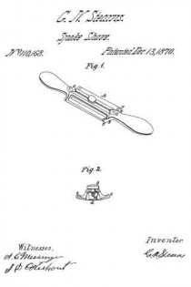
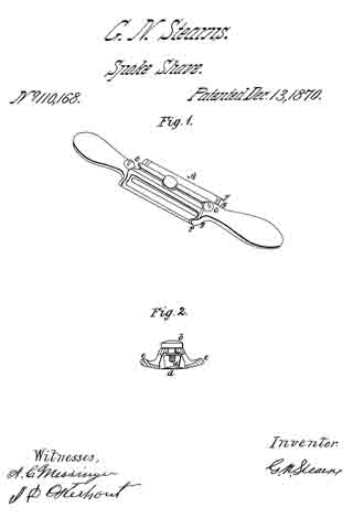
Figure 1 is a perspective view of the same.
Figure 2 is a sectional view, showing the gauge, one on each side of the knife, and the adjusting-screw inserted in the stock.

This invention relates to a new adjusting spoke-shave.

One object of my invention is in adjusting both sides of the gauge iron; the arms at the same time, thereby presenting a true and even cut the entire length of the knife.

To enable others skilled in the art to make and use my invention, I will proceed to describe its construction and operation.

In the accompanying drawings —

A represents the stock, which may be made any suitable shape or size, and of wood or metal. I prefer to make it in the shape shown in the drawing A, and of metal.

b represents the screw, inserted in the stock A for the adjusting of the gauge e e to and from the knife d.

The gauge e e is fastened to the stock A by the means of two bolts F F at the end of the arms g g.

The knife d is fastened to the stock A by the means of two screws C C, the knife d being stationary.

I am aware that other spoke-shaves have been constructed before my invention in which adjusting-gauges have been used in conjunction with knives, but such gauges and substances were differently arranged from mine, and are liable to many serious objections, which are removed by my arrangernents.

Therefore, I do not claim, broadly, the adjusting-gauge when arranged upon a different principle from that involved by my arrangements.

Having thus described my invention,

What I claim as new, and desire to secure by Letters Patent, is —

The spoke-shave herein described, consisting of stock A, gaugee e, constructed, arranged, and operating substantially as described.

GEO. N. STEARNS.

Witnesses:
A. C. MESSENGER,
HARRY GIFFORD.

No. 64,001 – Improvement In Plane Irons (William H. Eckert) (1867)

[paiddownloads id=”123″]64001


United States Patent Office.


WILLIAM H. ECKERT, OF SYRACUSE, NEW YORK.

Letters Patent No. 64,001, dated April 23, 1867.
_________________

IMPROVEMENT IN PLANE IRONS.

_________________

The Schedule referred to in these Letters Patent and making part of the same.

_________________

TO ALL WHOM IT MAY CONCERN:

Be it known that I, WILLIAM HENRY ECKERT, of the city of Syracuse, Onondaga county, New York, have invented a new and improved Plane; and I do hereby deciare that the following is a full, clear, and exact description of the same, reference being had to the annexed drawings, making a part of this specification.

The letters used represent corresponding parts wherever they occur.

To enable others skilled in the art to make and use my invention, I will proceed to describe the same, and its form when complete and ready for use.

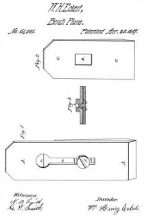
Figure 1 represents a perspective view of the plane irons when put together.

Figure 2 represents the cap.

Figure 3 represents a cross sectional view of both the plane irons, with the nut and screw.

In the common form of plane irons the screw is made to pass directly into the cap, for the purpose of holding the two irons together. This form of construction involves the necessity of unscrewing the cap when-ever the irons are separated for sharpening, or any other purpose of separation. The object of my invention is to dispense with this necessity and enable the irons to separate by simple handling.

I make the cutting iron A in all respects in the common form, with an elongated slot, a, for the movement of the screw s, and with a circular aperture, o, for the screw-head to pass through. Instead of inserting the screw in the cap, I make the nut n, which may be in any convenient form, square, oblong, circular, or other-wise; but I consider the oblong form the best, because best calculated to bold the cap straight with the cutting iron. In the cap C I make the slot or opening h, into which the nut n is made to fit, and it should be so made as to receive the nut with a snug joint. By this means the cap C, which in other respects is made in the common form, is readily adjusted by means of the screw and the irons, separated by slipping the cap C off from the nut n.

What I claim as my invention, and desire to secure by Letters Patent, is —

The nut n, in combination with the planing iron A, the screw s, and the cap C, made and operated substantially as and for the purposes described.

I also claim the slot h in the cap C, when made to it upon the nut n, and applied to planing irons, substantially as described.

WM. H. ECKERT.

Witnesses:
N. B. SMITH,
G. W. SMITH.