No. 1,270,744 – Plane Attachment (Joseph O. Langford) (1918)

[paiddownloads id=”720″]1270744


UNITED STATES PATENT OFFICE.

_________________

JOSEPH O. LANGFORD, OF EL PASO, TEXAS, ASSIGNOR OF ONE-HALF TO HENRY MOHR, OF EL PASO, TEXAS.

PLANE ATTACHMENT.

_________________

1,270,744. Specification of Letters Patent. Patented June 25, 1918
Application filed April 26, 1917. Serial No. 164,679.

_________________

To all whom it may concern:

Be it known that I, JOSEPH O. LANGFORD, a citizen of the United States, residing at El Paso, in the county of El Paso and State of Texas, have invented certain new and useful Improvements in Plane Attachments, of which the following is a specification.

This invention relates to planing tools and more particularly to an attachment therefor, in the nature of a guard or fender.

The principal object of the invention is to produce a guard for a plane-stock, whereby the hand of the operator is protected from injury by splinters, etc., during the use of the planing tool.

A further object of the invention is to produce a guard of this character which will prevent splinters and the like from striking the front ends of the side plates, and which may be readily attached to or detached therefrom whenever desired and with no difficulty whatsoever.

With these and other objects in view, my invention consists in the details of construction, arrangement and combination of parts, as will be hereinafter more fully described in the following specification and pointed out in the accompanying drawings, wherein:

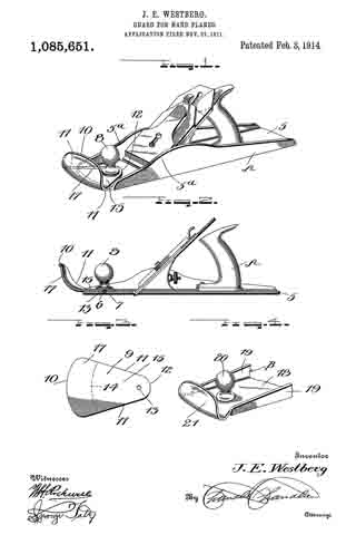
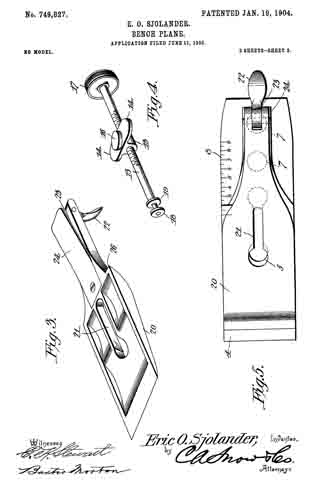
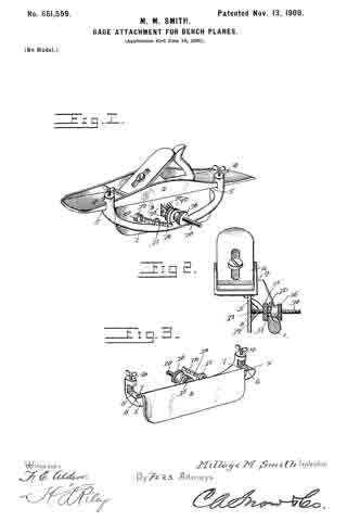
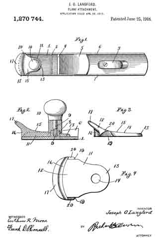
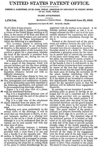
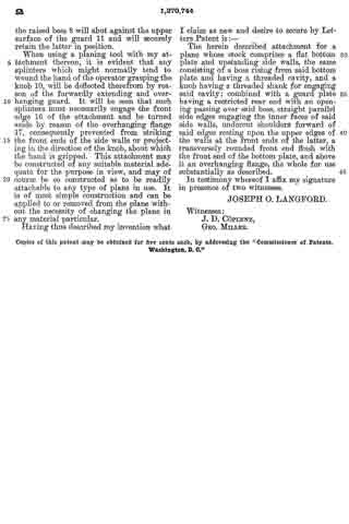
Figure 1 is a top plan view of a plane, with my attachment thereon, Fig. 2 is a longitudinal sectional view of the attachment and the end of the plane to which it is secured, Fig. 3 is a side view of the attachment shown detached from the plane, and Fig. 4 is a detail bottom plan view of the same.

Referring now more particularly to the several views of the drawings, it will be noted that my attachment is shown, in several instances, applied to a planing tool known in the art as a block or jack plane, although it is to be understood that the invention can be used equally well with any other type of plane.

In this particular instance, 1 indicates the flat lower surface of the plane stock provided with a cross brace 2 at one end and a handle 3 at the opposite end. This surface is further provided with a transversely extending slot 4 arranged in proximiity to the cross brace 2 and for the purpose of permitting the plane bit or cutting blade of the plane to extend therethrough for engagement with the surface to be planed. A suitable inclined support or rest 5 is arranged adjacent the slot 4 and is of the type usually employed for supporting the plane bit in its various adjustments through the slot 4.

Formed at the forward end of the plane stock and midway between the side walls 6 and 7 thereof, is a raised boss 8 having a threaded bore therein adapted to receive the threaded shank 9 of a knob 10. This knob constitutes a gripping means for the operator to permit him to control the movement of the plane while being used. When using the plane, the operator of course, propels it over the surface of the board, etc., by means of the handle 3, but it is well-known in the art that serious injuries have been occasioned by reason of the fact that large splinters have been forced into the hand which grasps the knob piece 10 during the movement of the plane, besides interfering with the proper manipulation of the planing tool. It is the object of my invention to overcome this objectionable feature and to provide a guard for the operator’s hand, so that the splinters will be deflected from engagement therewith.

In carrying out my invention I provide a shielding plate or guard 11 having an enlarged end 12 and a restricted end 13, the latter being provided with an opening 14 adapted to receive the raised portion 8 of the plane stock after the knob 10 has been unscrewed therefrom and the guard member attached to the plane in the manner illustrated to advantage in Fig. 2 of the drawings. The upper surface of the guard is inclined and projects forwardly beyond the rounded front edge 16 to provide an overhanging flange 17. The marginal edge of the restricted portion 13 is beveled as indicated at 18, said edge terminating abruptly on both side of the plate to provide parallel straight edges 19 for closely engaging the inner faces of the sides 6 and 7 respectively of the plane stock. Shoulders 20 are formed forward of the edges 19 for engagement with the front ends of the side walls 6 and 7 and are undercut as seen in Fig. 3 so as to conform to the curvature of said ends, thus permitting the guard member to be firmly seated in place when attached to the plane. The knob 10 when its shank 9 is screwed into the raised boss 8 will abut against the upper surface of the guard 11 and will securely retain the latter in position.

When using a planing tool with my attachment thereon, it is evident that any splinters which might normally tend to wound the hand of the operator grasping the knob 10, will be deflected therefrom by reason of the forwardly extending and overhanging guard. It will be seen that such splinters must necessarily engage the front edge 16 of the attachment and be turned aside by reason of the overhanging flange 17, consequently prevented from striking the front ends of the side walls or projecting in the direction of the knob, about which the hand is gripped. This attachment may be constructed of any suitable material adequate for the purpose in view, and may of course be so constructed as to be readily attachable to any type of plane in use. It is of most simple construction and can be applied to or removed from the plane without the necessity of changing the plane in any material particular.

Having thus described my invention what I claim as new and desire to secure by Letters Patent is :–

The herein described attachment for a plane whose stock comprises a flat bottom plate and upstanding side walls, the same consisting of a boss rising from said bottom plate and having a threaded cavity, and a knob having a threaded shank for engaging said cavity; combined with a guard plate having a restricted rear end with an opening passing over said boss, straight parallel side edges engaging the inner faces of said side walls, undercut shoulders forward of said edges resting upon the upper edges of the walls at the front ends of the latter, a transversely rounded front end flush with the front end of the bottom plate, and above it an overhanging flange, the whole for use substantially as described.

ln testimony whereof I affix my signature in presence of two witnesses.

JOSEPH O. LANGFORD.

Witnesses:
J. D. CÖPLENZ,
GEO. MILLER.

_________________

Copies of this patent may be obtained for five cents each, by addressing the “Commissioner of Patents, Washington, D. C.”
_________________

No. 1,085,651 – Guard For Hand-Planes (John E. Westberg) (1914)

[paiddownloads id=”693″]1085651


UNITED STATES PATENT OFFICE.

_________________

JOHN E. WESTBERG, OF EL CAMPO, TEXAS.

GUARD FOR HAND-PLANES.

_________________

1,085,651. Specification of Letters Patent. Patented Feb. 3, 1914.
Application filed November 27, 1911. Serial No. 662,640.

_________________

To all whom it may concern:

Be it known that I, JOHN E. WESTBERG, a citizen of the United States, residing at El Campo, in the county of Wharton, State of Texas, have invented certain new and useful Improvements in Guards for Hand-Planes; and I do hereby declare the following to be a full, clear, and exact description of the invention, such as will enable others skilled in the art to which it appertains to make and use the same.

This invention relates to improvements in bench planes.

The principal object of the invention is to provide a guard for bench planes which will prevent the shavings or splinters from contacting with and injuring the hand of the operator.

Another object of the invention is to provide a guard for the purpose described which is in the nature of an attachment and which can therefore be readily applied to any plane now in common use which includes the usual front handle.

A further object of the invention is to provide a guard attachment for the purpose described, which is formed from a single blank of metal, is therefore simple in construction, and is cheap to manufacture.

With these and other objects in view, the invention consists in the construction and novel combination of parts hereinafter fully described, illustrated in the accompanying drawings, and pointed out in the claim hereto appended; it being understood that various changes in the form, proportion, size and minor details of construction within the scope of the claim, may be resorted to without departing from the spirit or sacrificing any of the advantages of the invention.

In the drawing Figure 1 is a perspective view of a jack-plane showing my invention associated therewith, Fig. 2 is a longitudinal section through the same, the handle being shown in elevation, Fig. 3 is a plan view of the blank from which the guard attachment is formed, and Fig. 4 is a detail perspective view of the forward end of a jack-plane showing a modified form of my invention.

Like reference numerals designate corresponding parts in all the figures of the drawing.

Referring to the drawing, a bench plane is indicated as a whole by the reference character A. This plane includes the usual body or base 5 having a threaded recess 6 formed centrally in its forward end for the reception of a screw 7 carried by the usual knob or forward handle 8.

The preferred form of my invention, as illustrated in Figs. 1 to 3 inclusive, consists of a guard formed from a substantially triangular blank 9 of metal. This blank includes a curved base 10 and converging sides 11–11, said sides terminating in an apex 12. Formed in the apex thereof is an opening 13. The end of the blank opposite the opening 13 is transversely bent along the arcuate line la to form a consequent base 15 and an upstanding flange 17, said flange being centrally dished for a purpose hereinafter described. In attaching this guard to a plane, the opening 13 of said guard is placed in registration with the threaded recess 6 of the body 5. It will thus be observed that the body 15 of the guard is of such a length as to project the flange 17 slightly in advance of the front end of the body 5 of the plane. The knob or handle 8 is then secured by means of screws 7 to the body 5, and at the same time clamping the guard 9 against said body 5. It will furthermore be noted that the sides 11–11 of the guard abut against the side walls 5a of the body and thereby prevent any lateral swinging movement of said guard.

In the modification, as illustrated in Fig. 4 of the drawing, the plane B is formed with the usual body or base 18 and side walls 19–19. A front knob or handle 20 is secured in the usual manner to the base 18. The forward end of the base in advance of the handle 20 is bent upwardly to form an arcuate dished guard 21.

From the foregoing, it will be observed that when the plane is in operation, any shavings or splinters which would ordinarily contact with the operator’s hand, will be prevented by means of the guard as above described.

What is claimed is:

The combination with a frame including a body having side flanges and having a centrally disposed blade projecting therefrom, a handle carried by the body and arranged in rear of the blade, a handle carried by the body and arranged in front of the blade, and a guard for said front handle secured to the body by said handle and disposed in advance thereof and intermediate said flanges.

In testimony whereof, I affix my signature, in presence of two witnesses.

JOHN E. WESTBERG.

Witnesses:
J. E. McIVER,
CHAS. BLOOM.

_________________

Copies of this patent may be obtained for five cents each, by addressing the “Commissioner of Patents, Washington, D. C.”
_________________

No. 749,827 – Bench-Plane (Eric O. Sjolander) (1904)

[paiddownloads id=”596″]749827


UNITED STATES PATENT OFFICE.

_________________

ERIC O. SJOLANDER, OF DEEPWATER, TEXAS.

BENCH-PLANE.

_________________

SPECIFICATION forming part of Letters Patent No. 749,827, dated January 19, 1904.
Application filed June 11, 1903. Serial No. 161,054. (No model.)

_________________

To all whom it may concern:

Be it known that I, ERIC O. SJOLANDER, a citizen of the United States, residing at Deepwater, in the county of Harris and State of Texas, have invented a new and useful Bench-Plane, of which the following is a specification.

This invention relates generally to bench-planes, and more especially to means for adjusting the bit in the stock and means for securing the bit in adjusted position.

One object of the invention is to provide in a bench-plane an improved form of mechanism for adjusting the position of the bit in the stock, so that the depth of cut may be accurately adjusted and so that the edge of the bit may be brought into perfect parallelism with the face of the stock.

A further object of the invention is to provide in a bench-plane a bit bearing a scale and a bit-clamping plate bearing an indicator to cooperate with the scale on the bit to show when the bit and the clamping-plate have been brought into proper relation.

A further object of the invention is to provide in a bench-plane single means for adjusting the depth of the cut and for swinging the bit laterally on a suitable fulcrum to bring the cutting edge into parallelism with the stock.

In attaining the objects above stated and others which will hereinafter appear I make use of the construction and combination of parts of a bench-plane hereinafter described and claimed, and illustrated in the accompanying drawings, in which corresponding parts are designated by the same characters of reference throughout, it being understood that changes in the form, proportions, and exact mode of assemblage of the elements may be made without departing from the spirit of the invention.

In the drawings, Figure 1 is a view in vertical longitudinal section through the plane. Fig. 2 is a view of the plane-stock and bit-support. Fig. 3 is a view in perspective of the bit-clamping plate, showing the recessed back. Fig. 4 is a perspective view of the adjusting screw and block. Fig. 5 is a plan view of the bit and the bit-clamping plate, showing the clamping-plate adjusted in position by means of the scale on the bit.

Referring to the drawings in detail, 1 designates the plane-stock, which may be of wood or metal and of any of the ordinary forms. The stock is provided with the usual opening 2 for the passage of the bit, and on the upper surface of the stock, at the rear margin of the opening 2, is provided a supporting structure 3, the forward surface of which forms a continuation of the rear wall of the opening 2. The bit 4 consists, preferably, of a single plate of steel provided at its lower end with a cutting edge and having at 5 a slot with enlarged and rounded ends for the passage of the head of a screw 6, mounted in the lower end of the supporting structure. The width of the slot 5 between the rounded end portions is of such width as just to permit of the passage of the shank of the screw 6, which is designed to serve as a fulcrum, upon which the bit 4 may be swung laterally. The bit is provided near the butt with round openings 7, for purposes that will presently appear, and along one lateral margin of the bit is formed a scale 8, for use in connection with an indicator formed on the bit-clamping plate.

The supporting structure 3 is vertically slotted at 9 from the upper end almost to the base, and at the lower end of the slot 9, which tapers slightly toward the bottom, are provided a pair of oppositely-disposed ribs 10, which lie in a plane substantially at right angles with the front surface of the support. At either side of the slot 9 is an arm 11, on the forward surface of each of which is formed a shallow recess 12 to form a way for the movement laterally and transversely of the support of one of the wings 14 of a block: 13, which is carried on the screw 15, which is supported in the slot 9 in a manner presently to be explained.

The body portion of the block 13 is sufliciently narrow to be susceptible of considerable lateral movement in the slot 9, and the wings 14 are of such proportions that they will have a similar degree of lateral movement in the recesses 12. On the forward surface of the block 13, which lies substantially flush with the forward surface of the supporting structure 3, is provided a stud 16, which is adapted for engagement with either of the round openings 7 in the plane-bit. When the parts of the plane are assembled, the stud 16 will always be brought into engagement with one of the openings 7, and when the parts are so connected the movements of the block 13 will be communicated to the bit, and conseqently any shifting of the block 13 will change the position of the bit correspondingly.

The screw 15, upon which the block 13 is carried, is provided at its upper end with a head 17 of suitable form to facilitate the rotation of the screw, and at the lower end the screw has a reduced portion which is not threaded. At the extremity of the reduced portion a collar 18 is rigidly attached, and loose upon the reduced portion between the collar 18 and the threaded portion of the screw is a second collar 19. The opposite faces of both collars 18 and 19 are rounded, as best seen in Fig. 1, and when the collars are spread apart sufficient space is provided between them to permit the passage of the ribs 10, which are spaced apart sufficiently to allow the reduced portion of the screw to be introduced between them. The rounded faces of the collars 18 and 19 permit the screw 15 to be shifted laterally with the reduced portion between the ribs 10 as a pivotal point.

In order to clamp the bit 4 rigidly in proper relation to the stock 1, I provide a bit-clamping plate 20 of the form generally used, which is provided about midway of its length with a slot 21, having the lower end thereof enlarged and rounded to permit the passage of the head of the screw 6. At the upper end of the bit-clamping plate a cam-lever 22 is pivotally mounted in a slot 23 in the clamping-plate, and on the rear surface of the clamping-plate, which is preferably recessed, as shown in Fig. 3, there is provided near the upper end of the plate a tongue 24, of thin metal, which is rigidly attached at its lower end to the clamping-plate and has the upper end thereof, which is free, disposed under the cam on lever 22. The tongue 24 is provided to prevent the contact of the cam with the bit 4, as the contact of the cam with the bit would tend to throw the bit out of adjusted position.

On the side of the clamping-plate 20 which corresponds in position to the scale 8 on the bit there is formed a shoulder 26, which is adapted to serve as an indicator in connection with said scale and to show by the coincidence of the shoulder with one of the divisions of the scale when the clamping-plate has been brought into proper relation to the bit.

In assembling the parts of the plane for use the mode of procedure is as follows: The clamping-plate 20 and the bit 4 will first be brought into proper relation, as shown in Fig. 5, and the division of the scale with which the shoulder on the clamping-plate coincides will be noted. The bit will then be introduced into the opening in the stock, and the stud 16 on the block 13 will be brought into engagement with one of the openings 7 in the bit. If the bit is new and unworn, the lower opening will be employed, and if the bit is old and much worn the upper opening will be used. The bit having been operatively connected with the block 13, the screw 15 will be rotated by means of the head 17 on the end thereof until the edge of the plane-bit has been protruded beyond the face of the stock to the distance required for the proper depth of cut. Then the screw 15 will be swung laterally, if necessary, to bring the edge of the bit into perfect parallelism with the face of the stock. During the adjustment the operator will hold the plane in such position that the relation of the edge of the bit with the face of the stock may be accurately observed. When the bit has been properly adjusted, the clamping-plate 20 will be placed in position on the forward surface of the bit, with the screw 6 extending through the opening 21 in the plate. The clamping-plate will then be brought into exact position in relation to the bit by causing the shoulder 25 to coincide with the division of the scale 8, previously noted, and the cam-lever 22 will then be operated to secure the clamping-plate in adjusted position.

From the foregoing description of the construction and mode of adjustment of the plane it will be seen that the adjustment of the bit in relation to the plane-stock is effected independently of the adjustment of the clamping-plate and that the relative positions of the clamping-plate and bit to produce the desired result having been noted at the beginning of the operation of adjustment of parts of the plane the clamping-plate may be brought at once into proper relation to the bit and secured without deranging the adjustment of the bit in relation to the stock. It will also have been observed that by providing a scale on the bit and an indicator of a suitable form on the clamping-plate a degree of accuracy of adjustment of the clamping-plate and bit may be secured, which is impossible in planes not so constructed.

A special advantage inherent in the construction hereinbefore described is in the mode of supporting the screw 15 and the adjusting-block 13, by which it is made possible to effect the adjustment of the plane-bit as to depth of out and as to parallelism with the face of the stock by a single adjusting means.

Having thus described the construction and operation of my invention, what I claim as new, and desire to secure by Letters Patent, is —

1. In a bench-plane, the combination of a bit bearing a scale located above the mouth of the plane, and a bit-clamping member having an indicator adapted to cooperate with said scale.

2. In a bench-plane, the combination of a bit bearing a scale above the mouth of the plane, and a clamping member having a shoulder adapted to form an indicator for cooperation with said scale.

3. In a bench-plane, the combination of a bit having a scale located along one lateral margin thereof above the mouth of the plane, and a clamping member having an indicator adapted to cooperate with said scale.

4. In a bench-plane, the combination of a bit, a support for the bit having a slot within its supporting range, a block supported in said slot and susceptible of movement longitudinally and laterally therein, said block being adapted for positive connection with the bit, and a pivoted member mounted within said slot along which said block is longitudinally movable.

5. In a bench-plane, the combination of a bit, a block adapted for positive connection with said bit, and a screw upon which said block is supported, said screw being pivotally mounted to swing laterally.

6. In a bench-plane, the combination of a bit, a bit-support having a longitudinally-arranged slot, oppositely-disposed ribs provided at one end of the slot, a screw arranged in said slot having collars near one end for loose engagement with said ribs and a block mounted on said screw and adapted for lateral and longitudinal movement in said slot and also adapted for positive connection with said bit.

7. In a bench-plane, the combination of a bit, a bit-support having a longitudinaly-disposed slot, oppositely-disposed ribs, at the lower end of said slot, a screw arranged in said slot and having at the lower end collars spaced apart and having the opposite faces rounded for engagement with said ribs, and a block mounted on said screw and adapted for positive connection with said bit.

In testimony that I claim the foregoing as my own I have hereto affixed my signature in the presence of two witnesses.

ERIC O. SJOLANDER.

Witnesses:
J. H. JOCHUM, Jr.,
J. ROSS COLHOUN.

No. 661,559 – Gage Attachment For Bench-Planes (Millage Mathew Smith) (1900)

[paiddownloads id=”550″]661559


UNITED STATES PATENT OFFICE.

_________________

MILLAGE MATHEW SMITH, OF STOCKDALE, TEXAS.

GAGE ATTACHMENT FOR BENCH-PLANES.

_________________

SPECIFICATION forming part of Letters Patent No. 661,559, dated November 13, 1900.
Application filed June 16, 1900. Serial No. 20,552. (No model.)

_________________

To all whom it may concern:

Be i t known that I, MILLAGE MATHEW SMITH, a citizen of the United States, residing at Stockdale, in the county of Wilson and State of Texas, haveinvented a new and useful Gage Attachment for Planes, of which the following is a specification.

The invention relates to improvements in gage attachments for planes.

The object of the present invention is to improve the construction of gages for planes and to provide a simple, inexpensive, and efficient device adapted to he readily applied to the stock of a plane and capable of being set at different angles to the face of the same to enable the edge or face of a board or piece to be accurately planed at the desired angle.

The invention consists in the construction and novel combination and arrangement of parts hereinafter fully described, illustrated in the accompanying drawings, and pointed out in the claims hereto appended.

ln the drawings, Figure 1 is a perspective view of a plane provided with a gage attachment constructed in accordance with this invention. Fig. 2 is a transverse sectional view of the same, the plane being shown in elevation. Fig. 3 is a detail perspective view of the attachment, illustrating the manner of journaling the gage-plate on the supporting bar or piece.

Like numerals of reference designate corresponding parts in all the figures of the drawings.

1 designates a curved supporting har or piece arranged at one side of a plane 2 and extending downward and outward from the stock thereof and provided at its ends with clamps 3, consisting of upper perforated ears 4 and lower jaws 5, which are extended and provided with bearings 6 for the reception of journals or pintles 7 of a gage-plate 8. The clamps are adapted to engage the front and rear portions of the stock of the plane at one side thereof, and the upper perforated ears are threaded for the reception of screws 9, which are adapted to clamp the upper face of the stock of the plane at the inner face of the adjacent side or flange thereof, whereby the attachment is secureiy fastened to the stock.

The gage-plate 8, which is adapted to be arranged at different angles to the lower face of the plane to form a guide, is provided at its ends with the pintles 7, which are extended longitudinally from it and which are retained in the said bearings 6 by the stock when the attachment is clamped thereon, and they permit the gage-plate to swing inward and outward to and from the curved supporting piece or bar, which is extended outward and downward beyond the side of the plane, as clearly illustrated in Fig. 2.

The adjustment of the gage-plate is effected by means of a screw 10, pivoted to the said gage-plate at the outer face thereof and extending through an opening 11 of an ear 12, which is located centrally of the supporting bar or piece and which extends upward therefrom. The inner end or head of the screw is provided with a perforation for the reception of a pivot 13, which passes through a pair of perforated ears 14, extending outward from the center of the gage-plate. The adjusting-screw receives inner and outer nuts 15 and 16, located at opposite sides of the projecting portion or ear 12 of the supporting-piece and adapted to be adjusted to move the gage-plate inward and outward and capable of clamping the said ear 12, whereby the gage-plate is securely held at any adjustment. The supporting bar or piece 1 is provided with an upwardly-extending guide 17, located at a point between the adjusting device and one end of the supporting bar or piece and receiving a graduated bar or arm 18, and the latter is pivoted at its inner end between a pair of ears or lugs 19. The ears or lugs 19, which extend outward from the gage-plate and which are preferably formed integral with the same, are perforated for the reception of the pivot 20 of the graduated arm or bar. The graduated arm or bar will enable the gage-plate to be accurately set at the desired angle.

It will be seen that the device is exceedingly simple and inexpensive in construction, that it is adapted to be readily applied to a plane, and that it is capable of being readiiy set at the desired angle for enabling an edge or a face of a board to be accurately planed.

It will also be apparent that the gage-plate is detachably mounted on the supporting bar or piece and that the clamps which engage the stock of the plane and which secure the attachment to the same also operate to retain the journals or pintles of the gage-plate in the bearings of the supporting bar or piece.

What is claimed is —

1. In a device of the class described, the combination with a plane, of a gage-plate provided with pintles or journals, a supporting bar or piece having clamps for engaging the plane and provided in their engaging faces with open bearings receiving the journals or pintles of the gage-plate, said plane fitting over the open bearings and retaining the pintles or journals therein, and an ajusting device connecting the gage-plate with the supporting bar or piece, substantially as described.

2. In a device of the class described, the combination with a plane, of a gage-plate provided with pintles or pivots, a supporting bar or piece provided with clamps composed of lower jaws fitting against the plane and provided with open bearings receiving the pivots or pintles, the plane being arranged over the open bearings, whereby the gage-plate is removably secured to the supporting bar or piece by the engagement of the clamps with the plane, and clam ping-screws located above the said jaws and cooperating with the same, and an adjusting device connecting the gage-plate and the supporting-piece, substantially as described.

3. A gage attachment comprising a supporting bar or piece provided with clamps, a hinged gage-plate, an adjusting-screw pivoted at its inner end to the gage-plate and extending outward through an opening of the supporting bar or piece, nuts mounted on the adjusting-screw and located at the inner and outer sides of the supporting bar or piece, and a graduated bar or arm extending from the gage-plate and passing through a guide of the supporting bar or piece and arranged approximately parallel with the adjusting-screw, substantially as described.

In testimony that I claim the foregoing as my own I have hereto affixed my signature in the presence of two witnesses.

MILLAGE MATHEW SMITH.

Witnesses:
M. S. McGEE,
W. W. YOUNG.

No. 250,007 – Bench-Plane (George F. Sawyer) (1881)

[paiddownloads id=”317″]250007


UNITED STATES PATENT OFFICE.

_________________

GEORGE F. SAWYER, OF LIBERTY, TEXAS.

BENCH-PLANE.

_________________

SPECIFICATION forming part of Letters Patent No. 250,007, dated November 22, 1881.
Application filed July 5, 1881. (No model.)

_________________

To all whom it may concern:

Be it known that I, GEORGE F. SAWYER, of Liberty, in the county of Liberty and State of Texas, have invented certain useful Improvements in Plane Attachments, of which the following is a specification.

The object of my invention is to prevent dulling the cutting-edge of a plane-iron by the backward movements of the plane.

The invention consists in a stirrup pivoted to the sides of the plane in such a manner that the transverse piece of the stirrup passes through a transverse groove in the under surface of the plane, this groove increasing in height toward the rear of the plane, so that when the plane is drawn backward it will be slightly raised by this stirrup, so that the cutting-edge of the plane-iron cannot slide on the board being planed.

In the accompanying drawings, Figure 1 is a longitudinal elevation of a plane provided with my improved attachment, the same being shown in the position it has when the plane is being moved backward. Fig. 2 is a like elevation, showing the plane moving forward. Fig. 3 is a cross-sectional elevation of the same on the line x x, Fig. 1.

Similar letters of reference indicate corresponding parts.

A stirrup, A, of the same width as the plane B, has the outer surface of its transverse piece or bar C rounded or cylinder-shaped. This stirrup A is pivoted to the plane B in such a manner that the shanks of the stirrup extend into the recesses D in the lower parts of the sides of the plane, these recesses being united by a transverse groove, E, in the under or bearing surface of the plane, the transverse bar C passing through this groove. The groove increases in depth or height from the front to the rear on a curved line.

The operation is as follows: If the plane is moved in the direction of the arrow x’, as shown in Fig. 1, the stirrup A swings to the front edge of the recesses D, and is held in that position on account of the movement of the plane; but, the stirrup-shanks being longer than the distance from the pivot to the under side of the plane, the plane must be raised a short distance and the cutting-edge of the plane-iron G cannot slide on the board F, and consequently will not become dull or blunted; but when the plane is moved forward in the direction of the arrow y’, as shown in Fig. 2, the stirrup swings back and the plane is lowered, and the cutting-edge of the plane-iron G cuts into the board F.

This device is simple and can be attached to old as well as new planes.

I am aware that it is not broadly new to provide planes with rollers adapted to elevate the cutter above the board when the plane is being drawn backward.

Having thus described my invention, I claim as new and desire to secure by Letters Patent —

1. The combination, with a plane having lateral recesses and a transverse groove in its under surface, of a suitable stirrup having its shanks pivoted in said recesses and adapted to slide into said groove, substantially as shown and described.

2. The combination, with the plane B, provided with recesses D in the sides and a transverse groove, E, in the under surface, of the stirrup A, pivoted to the plane, substantially as herein shown and described, and for the purpose set forth.

GEORGE FREDERIC SAWYER.

Witnesses:
W. B. TAYLOR,
D. C. PALMER.