No. 326,435 – Beading-Tool (Elton P. Kendall And Ambrose S. Vose) (1885)
UNITED STATES PATENT OFFICE.
_________________
ELTON P. KENDALL AND AMBROSE S. VOSE, OF WINDSOR, VERMONT.
BEADING-TOOL.
_________________
SPECIFICATION forming part of Letters Patent No. 326,435, dated September 15, 1885.
Application filed March 28, 1885. (No model.)
_________________
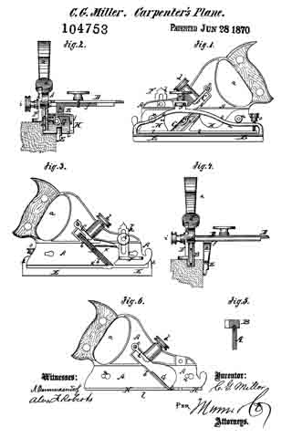
To all whom it may concern:
Be it known that we, ELTON P. KENDALL and AMBROSE S. VOSE, both citizens of the United States, residing at Windsor, in the county of Windsor and State of Vermont, have invented certain new and useful lmprovements in Beading-Tools; and we do declare the following to be a full, clear, and exact description of the invention, such as will enable others skilled in the art to which it appertains to make and use the same, reference being had to the accompanying drawings, and to letters or figures of reference marked thereon, which form a part of this specification.
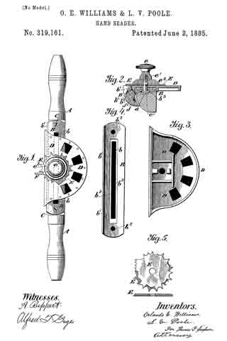
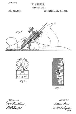
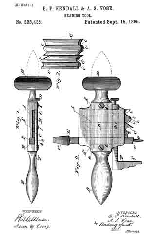
Figure 1 of the drawings is a vertical longitudinal seotion. Fig. 2 is a plan view. Fig. 3 is a detail view.
This invention relates to improvements in tools for cutting the beads and grooves of moldings and rosettes, and is adapted to be used on either wood, stone, or iron.
The invention consists, essentially, in firmly binding, edge to edge, in a metallic block a number of bar-shaped cutters or chisels, the cutting ends of which are formed and arranged to constitute the reverse of the contour of the molding, or one-half of the contour of the rosette to be formed.
The invention further consists in the construction of the cutting-edges of the chisels hereinafter described.
Referring to the accompanying drawings by letter, A represents a block of iron or steel, having on one of its side surfaces a shallow rectangular recess or out-away portion, A’.
A2 is a rectangular vertical recess in the floor of the recess A’, adjoining one side thereof, and for a purpose hereinafter explained.
B B are similar handles extending laterally from the side edges of the block A, and B’ is a plate adapted to be secured to the block A by the screws b b, so as to cover the recess A’ and bind the chisels, hereinafter described, between itself and the block in said recess.
C C, &c., are bar-shaped cutters or chisels of steel, rectangular in section, and with their sides parallel, so as to lie in the recess A’ with their sides pressed equally at all points by the block and plate B’. Their edges are also parallel, so that they will be bound together by the pressure of the set-screw D, which passes through a threaded opening in the edge of the block below the handle B on the edge opposite the recess A2.
The ends of the chisels may be made concave, convex, rectilinear at various inclinations, or of any desired contour; but whatever the contour of the end, its surface forms at all points a right angle with each side, so that the end has two cutting edges, c c, each of which has a pitch of ninety degrees. By this means the chisels may make either a draw cut or a push cut, according to the direction in which the block is moved, (the inclination being varied to suit the direction,) and, to complete the contour of the moldings, would make a draw cut and a push alternately.
The chisels, as is evident, are longitudinally adjustable, either separately or together in the block, and preferably have both ends provided with cutting-edges, as shown.
C’ is a modification of the ends of the chisels. In this case the vertical section of the end shows a U-shaped contour, the edges having a less pitch than ninety degrees.
One of the cutting-edges c may, if desired, be provided with the ricks c’ c’, to adapt it for certain kinds of work.
E is a bit having a rectangular shaft, e, and provided with the centering-point e’ and head e2’ on its lower and upper end, respectively. The shaft of the bit is held in the recess A2 by the plate B’, and its head is held for insertion into a brace or bit stock by which the bit and consequently the block and chisels are turned when forming a rosette. When the tool is used for moldings, the bit is removed and a rectangular shaft of the same diameter inserted in its place, against which shaft the chisels abut.
F is a gage-square laterally adjustable on the block by means of a proper slot and the set-screw f. The square is set so that its foot f’ will rest against the top or bottom of the molding and bring the chisels to the desired place. When turning rosettes,the gage-square is detached.
It is evident from the foregoing that any contour of molding or rosette may be formed by selecting the proper chisels and adjusting them to proper positions in the block A. Rosettes or moldings of different widths may be formed by binding on the block a greater or less number of chisels.
Having thus described this invention, what we claim is —
1. The improved beading-tool herein described, consisting of the holder-block A, recessed as shown, to receive the cutters, and having the recess E to receive the centering-bit, the plate or bar B’, adapted to secure the cutters and bit in their respective seats, and the set-screw D, passing through the threaded aperture in the holder-block to bind the cutters together, substantially as specified.
2. In a beading-tool, the combination, with the holder-block having the transverse recess to seat the cutters, of the plate B’, adapted to secure the cutters therein, and provided with a recess to receive a gage-square, the gage-square F, arranged at right angles to the cutters in the said recess, and the screw f, for adjustably securing the same therein, substantially as set forth.
In testimony whereof we affix our signatures in presence of two witnesses.
ELTON P. KENDALL.
AMBROSE S. VOSE.
Witnesses:
JOS. C. ENRIGHT,
GILBERT A. DAVIS.