No. 992,392 – Woodworking-Tool (John Tucholski And Antoni Edmond Koziczenski) (1911)

[paiddownloads id=”679″]992392


UNITED STATES PATENT OFFICE.

_________________

JOHN TUCHOLSKI AND ANTONI EDMOND KOZICZENSKI, OF RACINE, WISCONSIN.

WOODWORKING-TOOL.

_________________

992,392. Specification of Letters Patent. Patented May 16, 1911.
Application filed April 30, 1910. Serial No. 558,576.

_________________

To all whom it may concern:

Be it known that we, JOHN TUCHOLSKI and ANTONI EDMOND KOZICZENSKI, both citizens of the United States, and residents of Racine, in the county of Racine and State of Wisconsin, have invented certain new and useful Improvements in Woodworking-Tools; and we do hereby declare that the following is a full, clear, and exact description thereof.

Our invention consists in what is herein particularly set forth with reference to the accompanying drawings and pointed out in the claim of this specification, its object being to provide simple, economical and efficient tools of the spoke-shave species designed to facilitate smoothing, rabbeting and molding work without injury to operators, as well as to provide for accurate gaging of width of cut in rabbeting and molding operations, whether said tools be drawn or pushed by their operators as the grain of the wood worked upon may require.

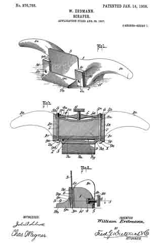
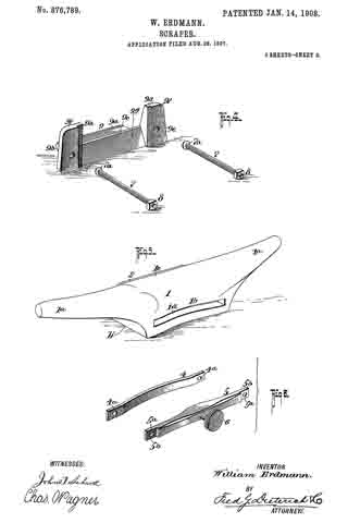
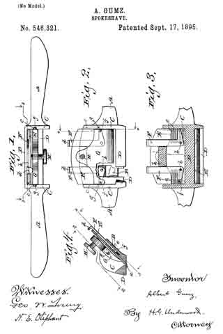
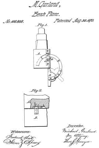
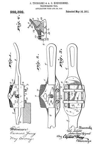
Figure 1 of the drawings represents a front elevation of a wood-working tool in accordance with our invention having a wedge clamping screw thereof partly broken away, and in this view the cutting of a rabbet is illustrated; Fig. 2, a plan view of the tool; Fig. 3, a similar view of the same reversed, and Fig. 4, a transverse section of said tool indicated by 4–4 in Fig. 2.

Referring by numerals to the drawings, 5 indicates the central stock, and 6 each of the oppositely extending handles of our improved tool said stock and handles being preferably cast together in one piece. The sole 7 is a central depending extension of the stock, whereby more than ordinary clearance is had under the handles, in order to prevent injury to the hands of an operator and to avoid marring of the work adjacent to a out of said tool, especially when the same is used upon curved work.

A longitudinal slot is provided in the forward portion of the stock through a depending flange 8 of the same, the under extremity of this flange being approximately flush with the sole, and said stock is provided with an angular bit and wedge opening such as is common in planes of various species. The bit 9, wedge 10 and clamp screws 11, 12 for the same herein shown, are also common in the art.

Matching the preferably beveled rear edge of the sole 7, we show hook-ends 13 of gage-bars 14, and each of these bars is provided with a socket-stud 15 that engages the slot 16 of the forward flanged portion of the tool-stock. The contour of each gage-bar stud and the tool-stock slot is such that there is wedging fit of one within the other, and a clamp-screw 17 is employed in engagement with said stud to draw and hold the same in said slot, the gage-bar being adjustable longitudinally of the sole (across which it extends) in proportion to the width of cut desired on the part of the bit in rabbeting or molding operations. By the employment of a pair of gage-bars, as is herein shown, adjusted equi-distant from the sides of the opposing sole, the tool may be drawn or pushed by an operator when cutting rabbets or moldings according as the grain of the wood worked upon is found to run one way or the other, said tool being turned about from time to time to change the cutting direction of its bit.

A straight edge bit being employed, as herein shown, the width of a rabbet may be accurately determined by an adjustment of one or both of the gage-bars 14, and the cutting of the rabbet can be more rapidly and accurately effected than is possible by chiseling. For smooth-work or wide molding, the gage-bars are omitted from the tool and said tool manipulated similar to those of the ordinary spoke-shave species, but to greater advantage because of the clearance afforded for the hands of the operator as above specified.

We claim:

In a woodworking tool of the spoke-shave species, the combination with its central stock having a forward depending and longitudinally slotted flange the under extremity of which is approximately flush with the sole of said stock, a gage-bar that crosses the aforesaid sole and has matching hook engagement with the same at the rear thereof, a socket-stud that extends from the gage-bar and has wedging fit with the slot of the stock-flange, and a clamp-screw engaging the stud.

In testimony that we claim the foregoing we have hereunto set our hands at Racine in the county of Racine and State of Wisconsin in the presence of two witnesses.

JOHN TUCHOLSKI.
ANTONI EDMOND KOZICZENSKI.

Witnesses:
CHRISTIAN JOHNSON,
MICHAEL OKOLEURKI.

_________________

Copies of this patent may be obtained for five cents each, by addressing the “Commissioner of Patents, Washington, D. C.”
_________________

No. 876,789 – Scraper (William Erdmann) (1908)

[paiddownloads id=”652″]876789


UNITED STATES PATENT OFFICE.

_________________

WILLIAM ERDMANN, OF MADISON, WISCONSIN.

SCRAPER.

_________________

876,789. Specification of Letters Patent. Patented Jan. 14, 1908.
Application filed August 28, 1907. Serial No. 390,520.

_________________

To all whom it may concern:

Be it known that I, WILLIAM ERDMANN, residing at Madison, in the county of Dane and State of Wisconsin, have invented a new and Improved Scraper, of which the following is a specification.

My invention relates to certain new and useful improvernents in scrapers for dressing floors and the like, and the invention primarily has for its object to provide a scraper of an improved construction which can be easily and cheaply manufactured and which will readily and effectively serve its intended purposes. In my invention means are provided for holding and clamping the scraping blade, which means can be easily and quickly adjusted to permit insertion or withdrawal of the blade, as the case may be.

Another object of my invention is to provide a scraper having a yielding pad against which the blade rests to absorb or prevent vibration when the implement is in use.

The invention also embodies certain novel construction, combination and arrangement of parts, all of which will be first described in detail and then be specifically pointed out in the appended claims, reference being had to the accompanying drawings, in which, —

Figure 1, is a perspective view of my invention. Fig. 2, is a central, vertical section thereof. Fig. 3, is a horizontal section on the line 3–3 of Fig. 2. Fig. 4, is a perspective view of the metallic gage and blade holding clamp member. Fig. 5, is a similar view of the stock and handle member. Fig. 6, is a perspective view of the bridge members.

Referring now to the accompanying drawings in which like letters and numerals of reference indicate like parts in all of the figures, 1 designates the stock with which the handles 1a merge, and the stock 1 has its under face plane, while its front face 1c is in a plane held at an obtuse angle to the plane containing the horizontal surfaces 1b of the stock.

Cemented or otherwise held in contact with the front face 1c of the stock 1, is a pad 2, of leather or other similar yielding material of substantially even thickness throughout, and against which the scraping blade 3 is held.

The blade 3 may be of the ordinary type and have the usual cutting edge 3a, as shown.

On the rear the stock 1 is formed with an elongated countersunk portion 1d to receive the bow shaped bridge member 4 and the set screw carrying bridge bar 5, the bar 5 having a threaded aperture to receive the set screw 6 and having its ends cut away as at 5b to form nut holding sockets.

The ends of the bars 4 and 5 have alining apertures 4a and 5a which register with the bolt holes 1x in the stock 1, to permit passage of the clamping bolts 7 which cooperate with the nuts 8, as shown.

9 designates the combined gage and blade holding clamp member which has the usual body 9a whose under face 9b lies in the same plane with that containing the face 1b of the stock 1. The body 9a has an upwardly projecting rear face 9c held at an acute angle to the face 9b and it also has upwardly projecting arms 9c having depressed blade receiving portions 9d and bolt apertures 9e together with a clearance space 9f to permit passage for the shavings.

In practice, the parts are arranged as shown in Figs. 1, 2 and 3. To loosen the member 9 and release the blade, it is only necessary to turn the set screw to ease up on the tension exerted on the bolt, when the blade may be easily withdrawn for sharpening or otherwise. When it is desired to reinsert the blade it is only necessary to replace the same in the position shown in Fig. 1, within the recesses 9d and tighten up on the set screw, thus exerting a tension on the bolts and drawing the member 9 against the blade, and tightly clamping the blade against the yieldable cushion or pad.

By constructing a scraper as shown and described, the same can be easily and cheaply manufactured at a minimum expense and the blade can be readily adjusted to its proper position as well as easily and quickly removed for sharpening, the provision of the yieldable pads serving to take up any vibrations which may occur during the operation of the implement and prevent chattering of the blade.

It will be noticed that the cut away ends of the set screw carrying bridge member 5 together with the countersunk portion of the stock 1 in which the bridge members are held, serve as a nut lock and prevent the nuts becoming loose, it being understood that the heads 7a of the bolts have their faces held at a slight angle to the longitudinal axis of the bolts, thus preventing turning of the bolt when the set screw is tightened up.

From the foregoing description, taken in connection with the accompanying drawings, it is thought the complete construction, opoperation and numerous advantages of my invention will be readily understood by those skilled in the art to which the invention appertains.

What I claim is, —

1. The combination with the stock, the blade holding clamp member, and means for mounting the blade holding clamp member on the stock, of means carried by the stock and cooperatively connected with the aforesaid mounting means for causing the blade carrying clamp member to clamp the blade against the stock substantially as shown and described.

2. The combination with the stock, the blade holding clamp member having blade receiving recesses and the blade therein, of securing means passed through the clamping member and the stock for holding the clamping member to the stock, and means for tightening up or loosening said securing means to clamp or release the blade, substantially as shown and described.

3. The combination with the stock, the blade holding clamp member having blade receiving recesses and the blade therein, of securing means passed through the clamping member and the stock for holding the clamping member to the stock, means for tightening up or loosening said securing means to clamp or release the blade, said last named means comprising a pair of bridge members carried by the stock and cooperatively connected with the securing means, and means carried by one of said bridge members for exerting a tension on said securing means to draw the blade holding clamp member tightly against the blade, substantially as shown and described.

4. The combination with the stock, the blade holding clamp member having blade receiving recesses and the blade therein, of securing means passed through the clamping member and the stock for holding the clamping member to the stock, means for tightening up or loosening said securing means to clamp or release the blade, said last named means comprising a pair of bridge members carried by the stock and cooperatively connected with the securing means, means carried by one of said bridge members for exerting a tension on said securing means to draw the blade holding clamp member tightly against the blade, and a yieldable pad interposed between the blade and the blade holding clamp member and the stock, substantially as shown and described.

5. The combination with the stock, the blade holding clamp member and the blade, and bolts for securing the blade holding member to the stock, of tension devices for said bolts to cooperate with the blade holding clamp members, substantially as shown and described.

6. The combination with the stock, the blade holding clamp member and the blade, and bolts for securing the blade holding member to the stock, of tension devices for said bolts to cooperate with the blade holding clamp members, said tension devices comprising a bridge member connected with said bolts, and means cooperating with the bridge member for exerting a tension on said bolts.

7. The combination with the stock, the blade holding clamp member and the blade, and bolts for securing the blade holding member to the stock, of tension devices for said bolts to cooperate with the blade holding clamp members, said tension devices comprising a bridge member connected with said bolts, means cooperating with the bridge member for exerting a tension on said bolts, said last named means comprising a set screw passing through said bridge member, substantially as shown and described.

8. The combination with the stock, the blade holding clamp member and the blade, and bolts for securing the blade holding member to the stock, of tension devices for said bolts to cooperate with the blade holding members, said tension devices comprising a bridge member connected with said bolts, means cooperating with the bridge member for exerting a tension on said bolts, said last named means comprising a set screw passing through said bridge member, and a supplemental bridge member held within said stock and adapted to be cooperatively engaged by said set screw, substantially as shown and described.

WILLIAM ERDMANN.

Witnesses:
ERNST SAABER,
REINHOLD MATHWIG.

No. 546,321 – Spokeshave (Albert Gumz) (1895)

[paiddownloads id=”517″]546321


UNITED STATES PATENT OFFICE.

_________________

ALBERT GUMZ, OF MILWAUKEE, WISCONSIN.

SPOKESHAVE.

_________________

SPECIFICATION forming part of Letters Patent No. 546,321, dated September 17, 1895.
Application filed January 20, 1894. Serial No. 497,499. (No model.)

_________________

To all whom it may concern:

Be it known that l, ALBERT GUMZ, a citizen of the United States, and a resident of Milwaukee, in the county of Milwaukee, and in the State of Wisconsin, have invented certain new and useful Improvements in Spokeshaves; and I do hereby declare that the following is a full, clear, and exact description thereof.

My invention relates to spokeshaves; and it consists in certain peculiarities of construction and combination of parts, as will be fully set forth hereinafter and subsequently claimed.

In the drawings, Figure 1 is a top view of the device partly in section. Fig. 2 is a front view of part of the same, partly broken away, and with the set-screw in section, on the line 2 2 of Fig. 4. Fig. 3 is a view with the parts in the same relative positions as in the preceding figure, but looking from the other side, with portions removed, on the line 3 3 of Fig. 4. Fig. 4 is a transverse sectional view on the line 4 4; of Fig. 2.

A A represent the handles of the device, and B the back-plate, C C the sides, and D the front bar of the frame or housing, all of these parts being preferably cast solidly together in one piece, leaving the usual slot or opening a for the passage of the cutting-blade E therethrough. On its under side this blade is provided with series of transverse grooves e e for engagement with pins or projections f f on the free ends of the short arms of the bell-crank levers F F, pivoted, as shown at b b, to the said back-plate B of the frame or housing. The long arms of these levers project beyond the top edge of said plate and terminate in thumb-pieces d d. The back-plate B is provided with a raised portion h to serve as a stop to limit the inward movement of the long arms of said levers F.

G is a retaining-plate adapted to rest on the upper side of the blade E, and provided at each side with projections or pins g g for engagement vvith grooves c c in the sides C C of the housing or frame.

H is a set-screw passing through a screw-threaded hole in the retaining-plate G, and bearing against the blade E when the latter has been adjusted.

The operation of my device will be readily understood from the foregoing description of its construction taken in connection with the accompanying drawings. The long arms of the levers F F are drawn inward against the stop h, and the blade E laid thereon with the pins f f in engagement with the grooves c c in said blade. The retaining-plate G is then placed upon the blade with the pins g g of said plate within the grooves c c in the side of the housing, and before the set-screw H is tightened the levers F F are moved out or in, so that the edge of said plate is advanced or retracted with relation to the opening on the required distance, and then the said set-screw H is tightened and the device ready for operation. By my device the blade may be adjusted evenly by simultaneous and equal movement of both levers; or, if preferred, either end of said blade may be advanced or retracted to a greater extent than the other end by simply operating the corresponding lever, and this can be done at any time by simply loosening the set-screw and operating the lever or levers without taking out the blade or detaching the parts, and hence a great saving of time is effected and the utmost nicety of adjustment insured.

From the foregoing it will be seen that the described bell-crank levers perform the double function of advancing and retracting the blade by a simultaneous movement of both and adjusting the edge of said blade to cut evenly by a slight independent movement of said beli-crank levers.

Having new fully described my invention, what I claim as new, and desire to secure by Letters Patent, is —

A spokeshave comprising a suitable handled housing, a blade, and a pair of pivoted bell-crank levers in engagement with said blade for advancing and retracting said blade by a simultaneous movement of both of said levers, and for adjusting the edge of said blade to cut evenly by a slight independent movement of the levers, substantially as set forth.

In testimony that I claim the foregoing I have hereunto set my hand, at Milwaukee, in the county of Milwaukee and State of Wisconsin, in the presence of two witnesses.

ALBERT GUMZ.

Witnesses:
H. G. UNDERWOOD,
HENRY DANKERT.

No. 313,540 – Bench-Plane (Roscoe S. Sheldon) (1885)

[paiddownloads id=”385″]313540


UNITED STATES PATENT OFFICE.

_________________

ROSCOE S. SHELDON, OF NORTH GREENFIELD, WISCONSIN.

BENCH-PLANE.

_________________

SPECIFICATION forming part of Letters Patent No. 313,540, dated March 10, 1885.
Application filed June 5, 1884. (No model.)

_________________

To all whom it may concern:

Be it known that I, ROSCOE S. SHELDON, of North Greenfield, in the county of Milwaukee, and in the State of Wisconsin, have invented certain new and useful Improvements in Combined Tools for Carpenters’ Use; and I do hereby declare that the following is a full, clear, and exact description thereof.

My invention relates to combined tools for carpenters’ use; and it consists in peculiarities of construction, as will be more fully described hereinafter.

In the drawings, Figure 1 is a perspective view showing my combined device. Fig. 2 is an elevation showing the opposite side of the same. Fig. 3 is a vertical section of the device on line x x of Fig. 2; and Fig. 4 is a perspective view of part of the plane-stock, showing the bit attachment. Fig. 5 is a perspective view of my improved plane-bit, and Fig. 6 is a like view of the slitting-tool holder.

The object of my invention is to produce a device equally well adapted to be used either as a grooving-plane or as a slitting-tool. I have also provided means whereby the same may he readily connected with a framing gage or guide; and to better adapt the plane for grooving across the grain of the wood and facilitate its passage in knotty lumber, I propose to make the plane-bit with cutting-spurs extending on each side and at right angles to the beveled rear face. These spurs thus project below the cutting-edge of the bit when this latter is fastened in place, and are adapted to cut deeper in the wood. With this construction, when the plane is used for grooving across the grain of the wood or in knotty lumber, besides the tool being handled with much greater ease, the grooves are cut with absolutely clean edges, which cannot be depended upon with ordinary plane-bits in like cases; but the bit herein shown and described I do not specifically and independently claim, and may use any bit which will cut a groove with clean edges.

A is the stock of my plane. B is the plane-bit, and C is the fastening-plate for the bit. The cutting-edge of the plane-bit is formed by beveling its rear face at b, except at the sides, which are left intact, but sharpened to form the cutting-spurs b b’. The rear edges of these spurs may, however, be rounded or cut on the same incline as that of the rear beveled face of the bit. The upper end of the plane-bit is beveled on the sides from rear to front, as shown at b2 b2 and the inner half of this dovetail-shaped end is received in the correspondingly-shaped groove or side of the throat a, formed in the front side of the stock A on the usual incline, being inserted from above in the usual manner of inserting plane-bits in general, when it is secured in place as follows: The fastening-plate C has a beveled notch, c, on its inclined front edge, to correspond with and clasp the outer beveled edge of the bit. The inner face of the plate C is beveled at c’ from its rear edge inward toward the notched front edge. This is done to allow for the play of the tightening-screw c2, the threaded end of which screws in a suitable threaded perforation of the stock A.

D is the slitting-disk, which I propose to mount in the grooving-plane stock, and which can be used therewith after the grooving-bit has been taken off. This disk, which is made of any suitable diameter and with a sharp edge, bears loosely on the threaded sleeve d, and the outer end of this sleeve fits in the perforation d’ of the supporting-plate D’. The stock-fence A is correspondingly perforated to receive the flat-headed bolt d2, the threaded end of which works in the threaded sleeve d. The support-plate D’ is provided on its inner face with the flanges d3 d4, on which it rests against the stock. These flanges are made of sufficient thickness to allow the slitting-disk D to freely rotate on its bearings. On the opposite side of the stock A a rectangular notch, a’, is formed, and a plate, a2, fastened onto the rear face of the plane-stock, covers the notch and forms a slot therewith. This closing-plate a2 is made so as to project a certain distance above the upper face ofthe stock, and is designed to act as a guide for the plane and enable it to move up or down along the vertical end ofthe angle-iron e. This latter forms a part of my improved joiner’s gage, and is suitably fastened in the under face of the graduated bar E of the same, sufficient space being left between the inner face of the angle-iron and the square end of the gage-bar to allow the guide-plate at to freely slide therein. It will also be observed that in order to enable the operator to give to the plane the rocking motion it requires the notch a’, formed in the rear face of the stock, is cut wider than the width of the angle-iron e. The gage is provided with the ordinary cross-head, E’, and adjusting-key e’. The cross-head E’ has also the usual flange, e2, formed on its under face; but in order to facilitate the handling of the tool in all kinds of work, I provide the detachable sole E2. This is made of the same thickness as that of the flange e2, and is held in place against the said flange when ordinary grooving is to be done, its inner edge being moved along the edge of the lumber, the same as the flange e2 is in the ordinary way of using the framing-gage. When, however, grooves have to be made across the grain of the wood and at any part of the board farther from this latter’s ends than can be reached with the gage in the ordinary manner, the sole E2 is then detached and fastened to the board in line with the projected groove. The flange e2 of the cross-head is then moved along the outer edge of the sole. In both cases, however, the operation of the grooving-plane is the same, as is readily understood from the above description and the accompanying drawings. As the cutting-edges of the bit penetrate the wood the plane is gradually lowered along the angle-iron e of the gage until the lower face of the stock rests against the upper face of the board or lumber. Obviously the gage can be used also with the slitting-tool in exactly the same manner.

Having thus described my invention, what I claim as new, and desire to secure by Letters Patent, is —

1. In a combined wood-working tool, in combination with the stock A, having notch a’ and guide~plate a2, the gage-bar E, having angle-iron e, and the cross-head E’, having detachable sole E2, substantially as shown and described, and for the purpose set forth.

2. In a grooving-plane, in combination with the stock A, having the throat a, with beveled side, and plate C, having the beveled notch c and beveled inner face, c’, with tightening-screw c2, the bit B, having beveled edges b2 b2, substantially as shown and described, and for the purpose set forth.

3. In a combined wood-working tool, in combination with the stock A, having a bearing for the bolt d2, the sleeve d, and supporting-plate D’, having flanges d3 d4, substantially as shown and described, and for the purpose set forth.

In testimony that I claim the foregoing I have hereunto set my hand, at Milwaukee, in the county of Milwaukee and State of Wisconsin, in the presence of two witnesses.

ROSCOE S. SHELDON.

Witnesses:
H. G. UNDERWOOD,
H. J. FORSYTHE.

No. 296,933 – Bench-Plane (Norman Edward Curtis) (1884)

[paiddownloads id=”364″]296933


UNITED STATES PATENT OFFICE.

_________________

NORMAN EDWARD CURTIS, OF MAUSTON, WISCONSIN.

BENCH-PLANE.

_________________

SPECIFICATION forming part of Letters Patent No. 296,933, dated April 15, 1884.
Application filed January 28, 1884. (Model.)

_________________

To all whom it may concern:

Be it known that I, NORMAN EDWARD CURTIS, of Mauston, in the county of Juneau and State of Wisconsin, have invented a new and Improved Bench-Plane, of which the following is a full, clear, and exact description.

In the class of bench-planes having adjustable plane-irons it is common to adjust the plane-iron longitudinally by means of an adjusting screw and lever, and to clamp the plane-iron and its cap by means of a clamping-lever provided with a cam.

My invention provides means for the accurate and quick lateral adjustment of the plane-iron, and it consists in a fulcrum upon which the plane-iron may swing laterally, a longitudinal groove formed in the rear face of the iron, and a lever fulcrumed in the lower part of the plane, with its shorter arm entering the groove in the back of the plane-iron, and its longer arm extending rearward, to be operated by hand or by an adjusting-screw.

Reference is to be had to the accompanying drawings, forming a part of this specification, in which similar letters of reference indicate corresponding parts in all the figures.

Figure 1 is a vertical longitudinal section of my improved plane, taken on the line x x in Fig. 2. Fig. 2 is a plan view. Fig. 3 is a detail view of the cap-iron. Fig. 4 is a rear view of the plane-iron. Fig. 5 is a vertical transverse section taken on the line y y y in Fig. 1. Fig. 6 is a vertical transverse section taken on the line z z in Fig. 1, the irons being removed.

The body of the plane is of the usual form, having the bed-piece A attached thereto in the usual way. In the upper surface of the bed-piece A is formed a groove, B, of sufficient width and depth to receive the screw C, which clamps the plane-iron D and cap-iron E together. The groove B is of sufficient length to permit the greatest required range of longitudinal rnovement of the plane-iron, while it embraces the sides of the screw-head so closely as to admit of little or no lateral motion of the plane-iron at that point. The shorter arm of a lever, F, fulcrumed in the bed-piece A, extends into an aperture, a, in the cap-iron E. The longer arm of the lever F is engaged by a milled nut, G, on the screw-threaded stud H, projecting from the back of the bed-piece A. By turning the milled nut G the plane-iron D is adjusted longitudinally in the usual way. The plane-iron D and cap-iron E are clamped in place by a clamping-lever, I, having a slot bolt hole, b, near its lower end for receiving the screw c, which also passes through the plane-iron and the cap-iron. A cam-lever, J, pivoted in the upper end of the clamping-lever, presses on a bearing plate, d, carried by the lever I, and which, in turn, presses upon the upper end of the cap-iron. The lever I is similar to others in use; but lf have shortened the distance between the screw c and the lower end thereof, and have increased the distance between the said screw and the cam-lever J, so as to secure an increased leverage and a corresponding increase in the firmness with which the plane-iron is held in place.

In the back of the plane-iron D and from the lower end thereof along the middle a groove, e, extends toward the usual longitudinal slot, f, of the plane-iron.

In a mortise formed in the lower portion of the bed-piece A a lever, K, is fulcrumed, so as to swing in a plane parallel with the face of the plane-body. The shoulder-arm h of the lever K is beveled and provided with a tongue, L, entering the groove e in the back of the plane-iron D. The longer arm i of the lever K, extends beyond the rear of the bed-piece A, where it may be moved by the hand alone or by any suitable mechanical device. I prefer to employ a screw, M, journaled transversely in the plane-body, and having a milled head, j, and carrying a traveling nut, N, having a loop, k, for receiving the longer arm i of the lever K. By turning the screw M in one direction or the other the lever K is correspondingly moved, and the plane-iron, by virtue of its engagement with the lever, is swung laterally, the clamping-screw C being the center of motion. This adjustment enables the user to readily and accurately adjust the cutting-edge of the plane-iron to parallelism with the face of the plane; and, furthermore, the tongue L at the end of the lever K forms a guide which permits of replacing the plane-iron in the plane-body without the necessity of special adjustment each time it is removed and replaced. Where a single iron is used, a screw corresponding to the clamping-screw C will be inserted in the back thereof to form a pivot on which the iron may swing.

I have described one term of my invention. It is obvious that it adrnits of various modifications, such as substituting a rib for the groove in the back of the iron and making a groove for its reception in the end of the adjusting-lever. The adjusting-lever may be bifurcated and made to embrace the edges of the plane-iron when neither the groove nor the rib would be required. It will also be seen that the adjusting-screw may be arranged to act directly on the plane-iron to secure the necessary lateral movement. In view of these various possible modifications of my improvement, I do not limit or confine my invention to the precise form herein shown and described.

Having described my invention, I claim as new and desire to secure by Letters Patent —

1. In a bench-plane, the combination, with the pivoted plane-iron having in its lower rear side a longitudinal groove of the laterally-adjustable lever adapted to fit into the groove of the plane iron, and capable of adjustment by the hand, substantially as and for the purpose set forth.

2. In a bench-plane, the combination, with the longitudinally-grooved bed-piece, of the cap-iron having the rear headed projection or screw, with its head entering the groove of said bed-piece, and the adjusting-lever engaging said iron, and actuated by an adjusting-nut, substantially as and for the purpose set forth.

3. In a bench-plane, the combination, with the pivoted plane-iron having in its lower rear surface a longitudinal groove, of the laterally-adjustable lever having a tongue entering the groove of the plane-iron, and the headed screw carrying a nut or sleeve provided with a loop which receives the outer end of the aforesaid lever, substantially as and for the purpose set forth.

NORMAN EDWARD CURTIS.

Witnesses:
JOHN F. CURTIS,
GEORGE CURTIS.

No. 296,785 – Plane (Joseph B. Ripsom) (1884)

[paiddownloads id=”363″]296785


UNITED STATES PATENT OFFICE.

_________________

JOSEPH B. RIPSOM, OF OSHKOSH, WISCONSIN.

PLANE.

_________________

SPECIFICATION forming part of Letters Patent No. 296,785, dated April 15, 1884.
Application filed July 21, 1884. (No model.)

_________________

To all whom it may concern:

Be it known that I, JOSEPH B. RIPSOM, a citizen of the United States, residing at Oshkosh, in the county of Winnebago and State of Wisconsin, have invented a new and useful Plane, of which the following is a specification, reference being had to the accompanying drawings.

This invention relates to carpenters’ planes, and is especially adapted for use as a carriage-maker’s miter-plane. Its object is to provide a plane possessing superior advantages in point of simplicity, inexpensiveness, durability, and general efficiency.

In the drawings, Figure 1 is a perspective view of my improved plane. Fig-2 is a vertical longitudinal sectional view of the same. Fig. 3 is a vertical transverse sectional view taken on the line x x, Fig. 2. Fig. 4 is a top view of the plane with the bit, cap-plate, and eccentric lever removed. Fig. 5 is a detail perspective view of the bit. Fig. 6 is a detail perspective view of the cap-plate.

Referring to the drawings, A designates the stock, which is formed of metal and provided with the usual handle, B. This stock comprises a bottom plate, C, at the side edges of which are provided longitudinal flanges D D, that incline outwardly and upwardly from plate C at an angle, preferably, of forty-five degrees. The throat or slot E extends entirely across the plate C, so that the bit or cutter extends to the vertex of the angles formed by plate C and flanges D D. A transverse brace-plate, F, is preferably formed between the flanges D D and just in front of the throat E, while a transverse rib, G, is provided some distance in rear of the throat, and is formed with a screw-threaded recess, H. Between this rib G and the throat E are provided upright side danges I I, having perforations J, in which a cross-pin, K, is secured.

L is a lever-block, which is provided with an elongated perforation, M, at its front end, through which passes a fulcrurn-screw, N, into the recess H, and has also upright side flanges, O O, at this end, formed with perforations P. At the rear end of this lever-block is formed a screw- threaded perforation, Q, through which works a set-screw, R, against the bottom plate, C, to raise and lower the said lever, by which operation the bit can be set at different angles for convenience in cutting with or across the grain of the wood.

S is a bed-plate, which is provided with a longitudinal slot, T, having longitudinal side shoulders, U U, and also has downwardly-extending side flanges V V, formed with perforations W, through which a cross-pin, X, is passed to pivot the bed-plate to the lever-block. The bed-plate extends down between the flanges I I, and a set-screw, Y, works through the slot T, with its head against the shoulders U U, into a block or nut, Z, bearing against the under side of the bed-plate. The head of this set-screw engages a cross-slot, A2, in the bit or cutter B2, to retain the latter in position, and the screw is only to be moved as the cutter wears away.

C2 is a cap-plate, which is preferably formed of steel, and is bowed to form a spring, as shown. This plate is preferably formed with end shoulders, D2 D2, which engage corresponding shoulders, E2 E2 at each side the throat E.

F2 is an eccentric lever, comprising an operating-handle, G2, and an eccentric head, H2, formed with a transverse groove, l2, by which it can be engaged under the pin K, to bind against the spring-plate and secure the bit in position against the bed-plate.

The operation and advantages of my invention will be readily understood and appreciated. It is very sirnple and efiicient in construction, and its parts can be easily governed and adjusted. By turning the set-screw R the bit will be given cut, and when the screw is turned back the tension of the spring cap-plate will automatically return the bit to its former position.

I claim as my invention —

1. The combination, with the stock comprising the bottom plate having the longitudinal side flanges inclined outwardly and upwardly at an angle from the bottom plate, and formed with the throat extending entirely across the bottom plate to the vertex of the angle formed by the bottom plate and side danges, of a lever-block fulcrumed on the stock, a set-screw for operating the said lever, a bed-plate connected with the lever, the bit carried by the bed-plate, and means for securing the bit in position, substantially as set forth.

2. The combination of the stock having the throat and upright flanges, the cross-pin between the latter, the lever-block having the fulcrum-perforation, and disposed just above the bottom plate and in rear of the throat, the fulcrum-screw, the set-screw for adjusting the lever, the longitudinally-slotted bed-plate pivoted on the lever, the set-screw working in the slot in the bed-plate, the bit having the slot for receiving the head of this screw, the spring cap-plate, and the eccentric lever under said cross-pin and acting to clamp down the spring cap-plate, substantially as and for the purpose set forth.

3. The combination, in a plane, of the main bottom lever, the set-screw working through the free end of the lever, a bed-plate pivoted to the lever at its fulcrurn end, the bit or cutter connected with the bed-plate, the bowed spring cap-plate, the cross-pin K, and the eccentric lever adjustable under this pin and against the springplate, whereby the bit can be adjusted by the set-screw and will be returned by the said spring-plate, substantially as set forth.

4. The combination of the bed-plate having the longitudinally-disposed slot formed with longitudinal side shoulders, the set-screw working through the slot with its head against the shoulders, the nut receiving the screw and bearing against the under side of the bed-plate, and the bit having the transverse slot that received the head of the set-screw, the bit being carried and adapted to be fed by adjusting said screw, substantially as set forth.

5. The combination of a bed-plate, the bit or cutter connected thereto, the bowed spring cap-plate, the cross-pin K, and the eccentric lever having the eccentric head formed with the transverse slot, substantially as and for the purpose set forth.

In testimony that I claim the foregoing as my own I have hereto aftixed my signature in presence of two witnesses.

JOSEPH B. RIPSOM.

Witnesses:
JOHN BAUMGARTNER,
GUSTAV EILERS.

No. 133,632 – Improvement In Carpenters’ Plane-Irons (Albert N. Cross) (1872)

[paiddownloads id=”205″]133632


UNITED STATES PATENT OFFICE.

_________________

ALBERT N. CROSS, OF NECEDAH, WISCONSIN.

IMPROVEMENT IN CARPENTERS’ PLANE-IRONS.

_________________

Specification forming part of Letters Patent No. 133,632, dated December 3, 1872.

_________________

To all whom it may concern:

Be it known that I, ALBERT N. CROSS, of Necedah, in the county of Juneau and State of Wisconsin, have invented certain new and useful Improvements in Carpenters’ Plane-Irons; and I do hereby declare that the following is a full, clear, and enact description thereof, that will enable others skilled in the art to which it appertains to make and use the same, reference being had to the accompanying drawing and to the letters of reference marked thereon which form a part of this specification.

The nature of my invention consists in a cap and case used with a plane-iron, and so constructed that the cap can be set or adjusted at any distance from the edge of the blade, and the two together raised or lowered in the case, as will be hereinafter more fully set forth.

In order to enable others skilled in the art to which my invention appertains to maize and use the same, I will now proceed to describe its construction and operation, referring to the annexed drawing, in which —

Figure 1 is a plan view, Fig. 2 a side view, and Fig. 3 a longitudinal section, of my invention.

A represents the plane iron or blade, B the cap, and C the case. The case C is in the center, on the front, provided with two slots, a and b, the slot a, extending from the upper edge downward for a suitable distance, and at the lower end of said slot is formed a projection, d, on the outside of the case. Below this projection d is the slot b, running on the same line with the former slot. The blade A is also slotted, as shown in Fig. 3, and is, with the cap B, placed in the case. A screw, e, is then passed through the slot b of the case and through the slot in the blade, and screwed into the cap B, thus securing the blade and cap firmly together. By means of the slot in the blade the cap may be set at any desired distance from the edge of the blade to do good work. On the front side of the blade A, at or near the upper end, is a short post or projection, f the outer end of which has a hole with female-screw threads. Through this is passed a thumb~screw, D, the lower end of which goes loosely through the projection d on the case, and has a nut on its end to prevent its being withdrawn. By means of this thumb-screw D the blade is raised or lowered at will for thin or thick shavings, and, the cap being fastened to the blade, the two are of course adjusted at the same time.

The case C is to be wedged in the stock so as to be firm in the same, the whole forming a very convenient and useful improvement in planes.

Having thus fully described my invention, what I claim as new, and desire to secure by Letters Patent, is —

The within-described plane-iron, consisting of the slotted blade A, cap B, and slotted case C, the blade and cap being adjusted together by the set-screw e placed within the case and operated by the thumb-screw D, in the manner and for the purposes herein set forth.

In testimony that I clairn the foregoing I have hereunto set my hand.

ALBERT N. CROSS.

Witnesses:
E. S. MINER,
B. F. BUCK, JR.

No. 106,808 – Improvement In Plane-Guide (Michael Garland) (1870)

[paiddownloads id=”170″]106808


United States Patent Office.


MICHAEL GARLAND, OF WEST EAU CLAIRE, WISCONSIN.

Letters Patent No. 106,808, dated August 30, 1870.
_________________

IMPROVEMENT IN PLANE-GUIDE.

_________________

The Schedule referred to in these Letters Patent and making part of the same.

_________________

To all whom it may concern:

Be it known that I, MICHAEL GARLAND, of West Eau Claire, in the county of Eau Claire and State of Wisconsin, have invented a new and useful Improvement in Plane-Guides; and I do declare that the following is a true and accurate description thereof, reference being had to the accompanying drawing, and to the letters of relerence marked thereon, and being a part of this specification, in which —

Figure 1 is an elevation of the front end of my improved plane and guide; and
Figure 2 is a longitudinal section of a part of the plane above the joints.

Like letters indicate like parts in each figure.

The nature of this invention relates to the construction of a guide-attachment to carpenters’ planes, and consists in a novel and peculiar construction of the guide, and method of attaching the same to an ordinary plane, so that the edge of a board may be jointed with perfect truth to a right angle with the side of the board, or to any bevel.

In the drawing —

A represents the body of an ordinary plane, and B, my guide, provided, at its upper edge, with two halves of a loose butt, d, with its pin engaging with an eye-bolt, C, two of which are screwed into the lower face of the plane, in line with the outer edge of the plane-iron.

A catch-spring, e, is secured in a recess at the rear of each eye-bolt, in such a manner that, when the butt-pins are hinged in the eye-bolts, the former cannot be withdrawn and disengaged from the latter, until the springs are depressed; but one spring is required to hold the guide in place, although two are preferable.

D is a circular segment secured to the front end of the guide, passing through a guide, D’, secured in the front end of the plane, and provided with a clamp-screw, d. This arrangement enables the workman to adjust and secure the guide to any desired angle with the plane, so that the edge of a board may be jointed with perfect truth to the angle set.

When not required the guide is detached, and the eye-bolts and spring removed.

I am aware of the invention of William H. Blye, for which Letters Patent of the United. States were granted to him on the 10th of April, 1849, and disclaim the same.

What I claim as my invention, and desire to secure by Letters Patent, is —

The plane-guide D’, provided with the clamp-screw d, in combination with the segment D, in connection with the plane A, provided with the guide B, half-butts a, eye-bolts C, and catch-springs c, when the several parts are constructed and arranged as described and shown, and for the purpose set forth.

MICHAEL GARLAND.

Witnesses:
H. F. EBERTS,
SAML. E. JONES.

No. 33,240 – Improvement In Planes (Abraham S. Cross) (1861)

[paiddownloads id=”93″]33240


UNITED STATES PATENT OFFICE.

_________________

ABRAHAM S. CROSS, OF RIPON, WISCONSIN.

IMPROVEMENT IN PLANES.

_________________

Specification forming part of Letters Patent No. 33,240, dated September 10, 1861.

_________________

To all whom it may concern:

Be it known that I, ABRAHAM S. CROSS, of Ripon, in the county of Fond du Lac and State of Wisconsin, have invented certain new and useful Improvements in Joiners’ Planes; and I do hereby declare that the following is a full, clear, and exact description of the same, reference being had to the accompanying drawing, and to the letters of reference marked thereon.

In the annexed drawing, making part of this specification, A represents the body or stock of the plane, which is constructed in any of the known and usual ways. Upon each end of this stock is secured a plate 1, made of metal. These plates are both provided with circular-formed slots 3.

2 represents a bent arm, which is secured through its angular portion to the plane-stock by means of a screw 5. This arm turns upon the screw 5 as a center. When the screw is tightened the arm is made fast to the stock. One end of the arm is provided with a slot 4. A set-screw 6 passes through this slot and also through the slot 3. This screw 6 is so arranged as to allow the arm 2 to partially revolve when necessary and also to station it at any desired point. By means of the slot 4. the arm 2 is enabled to turn farther than it could otherwise do, as is clearly evident, and is thus enabled, with the help of the guide 7, to form a miter.

7 is the guide upon the end of the arm for holding the plane to its position at any angle at which it is set. This guide, together with the arm 2, may be removed at any time by simply removing the screws 5 and 6, thus making the common plane of it. The end plates with this attachment may be used upon any common joiner’s plane.

I claim —

1. The combination of the arm 2, provided with slot 4, with the slot in plate 1 for the purpose of extending the slot 3 to form a miter.

2. The combination of the guide 7, the arm 2, the slotted end plates 1, and the screws 5 and 6, when the several parts are constructed and arranged in the manner herein set forth.

ABRAHAM S. CROSS.

In presence of —
A. H. BOOTH,
E. G. GRANT.

No. 81,795 – Bench Plane For Cutting Blind-Slats (Carl Kupfer) (1868)

[paiddownloads id=”51″]81795


United States Patent Office.


CARL KUPFER, OF MADISON, WISCONSIN, ASSIGNOR TO HIMSELF AND KUND
J. FLEISCHER, OF SAME PLACE.

Letters Patent No. 81,795, dated September 1, 1868.

IMPROVEMENT IN PLANES FOR CUTTING BLIND-SLATS.

_________________

Specification of Letters Patent No. 81,795 dated July 4, 1854.

_________________

The Schedule referred to in these Letters Patent and making part of the same.

_________________

TO ALL WHOM IT MAY CONCERN:

Be it known that I, CARL KUPFER, of Madison in the county of Dane, and State of Wisconsin, have made new and useful Improvements in Slat-Cutting Machinery ; and I do hereby declare the following to be a full, clear, and exact description of the nature, construction, and operation of the same, sufficient to enable one skilled in the art to which it appertains to construct and use the same, reference being had to the accompanying drawings, which are made part of this specification, and in which —

Figure 1 is a perspective view.
Figure 2 is an end sectional view.
Figure 3 is an enlarged side sectional view.
Figure 4 is a side sectional view.

The invention consists in the construction of a knife or plane bit, whose edge or edges are so shaped, arranged, and combined as to cut the top, sides and bottom of the slat at one stroke of the plane across the stick of timber from which the slat is to be cut, and in leaving a straight edge or side, against which the shoulder of the plane is brought, and which serves as a guide for the plane in cutting each succeeding slat.

The bit A is made of a piece of steel, of suitable dimensions for the size of the slat to be cut, with its lower cutting-end, B, bent to an angle of forty-five degrees, or thereabouts, from the line of the body of the bit, and projecting downwards, as shown at B, fig 4. This projection is pierced with a hole, as at C, fig. 2, of any desired shape for the slat, and in line with the face of the plane D, as shown at C, fig. 2; the upper and lower edges of the aperture being brought to sharp cutting-edges, as at 1 2, fig. 2.

In sharpening these edges, care must be taken to leave two lips, whose edges, 3 4, fig. 2, are at right angles with the upper and lower cutting-edges 1 2. The bit A is set in a plane-stock, D, and secured in the ordinary manner with a wedge, E, there being sufficient throat, F, for the escape of all shavings. The front end of the plane-stock is provided with a handle, G, to facilitate holding the tool firmly.

By the use of this tool I am enabled to avoid the use of sawed lumber of any kind, and, instead, use timber as it is split from the log, like fire-wood, or without splitting at all, and thus I save from one-half to nine-tenths of the timber, and consequently a large proportion of the cash outlay formerly paid for stock.

Having described my invention, what I claim, and desire to secure by Letters Patent, is —

1. The bit A, when constructed with sharpened upper and lower edges, 1 and 2, leaving two lips, 3 and 4, said lips to be at right angles with the upper and lower cutting-edges, substantially as and for the purpose set forth.

2. The combination of the bit A, as described and claimed, with the plane-stock, for the use and purposes specified.

CARL KUPFER.

Witnesses:
J. C. SCHELTE,
A. JURGENS.