No. 166,239 – Improvement In Bench-Planes (David F. Williams) (1875)

[paiddownloads id=”250″]166239


UNITED STATES PATENT OFFICE.

_________________

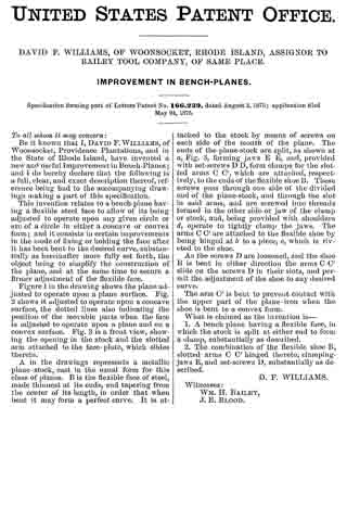
DAVID F. WILLIAMS, OF WOONSOCKET, RHODE ISLAND, ASSIGNOR TO BAILEY TOOL COMPANY, OF SAME PLACE.

IMPROVEMENT IN BENCH-PLANES.

_________________

Specification forming part of Letters Patent No. 166,239, dated August 3, 1875; application filed May 24, 1875.

_________________

To all whom it may concern:

Be it known that I, DAVID F. WILLIAMS, of Woonsocket, Providence Plantations, and in the State of Rhode Island, have invented a new and useful Improvement in Bench-Planes; and I do hereby declare that the following is a full, clear, and exact description thereof, reference being had to the accompanying drawings making a part of this specification.

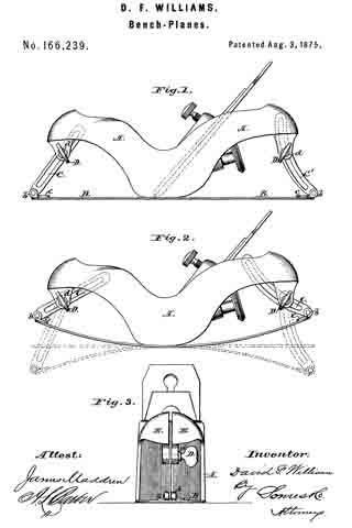
This invention relates to a bench-plane having a flexible steel face to allow of its being adjusted to operate upon any given circle or arc of a circle in either a concave or convex form; and it consists in certain improvements in the mode of fixing or holding the face after it has been bent to the desired curve, substantially as hereinafter more fully set forth, the object being to simplify the construction of the plane, and at the same time to secure a firmer adjustinent of the flexible face.

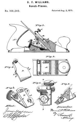
Figure 1 in the drawing shows the plane adjusted to operate upon a plane surface. Fig. 2 shows it adjusted to operate upon a concave surface, the dotted lines also indicating the position of the movable parts when the face is adjusted to operate upon a plane and on a convex surface. Fig. 3 is a front view, showing the opening in the stock and the slotted arm attached to the face-plate, which slides therein.

A in the drawings represents a metallic plane-stock, cast in the usual form for this class of planes. B is the flexible face of steel, made thinnest at its ends, and tapering from the center of its length, in order that when bent it may form a perfect curve. It is attached to the stock by means of screws on each side of the month of the plane. The ends of the plane-stock are split, as shown at a, Fig. 3, forming jaws E E, and, provided with set-screws D D, form clamps for the slotted arms C C’, which are attached, respectively, to the ends of the flexible shoe B. These screws pass through one side of the divided end of the plane-stock, and through the slot in said arms, and are screwed into threads formed in the other side or jaw of the clamp or stock, and, being provided with shoulders d, operate to tightly clamp the jaws. The arms C C’ are attached to the flexible shoe by being hinged at b to a piece, c, which is riveted to the shoe.

As the screws D are loosened, and the shoe B is bent in either direction the arms C C’ slide on the screws D in their slots, and permit the adjustment of the shoe to any desired curve.

The arm C’ is bent to prevent contact with the upper part of the plane-iron when the shoe is bent to a convex form.

What is claimed as the invention is —

1. A bench plane having a flexible face, in which the stock is split at either end to form a clamp, substantially as described.

2. The combination of the flexible shoe B, slotted arms C C’ hinged thereto, clamping-jaws E, and set-screws D, substantially as described.

D. F. WILLIAMS.

Witnesses:
WM. H. BAILEY,
J. E. BLOOD.

No. 166,240 – Improvement In Bench-Planes (David F. Williams) (1875)

[paiddownloads id=”251″]166240


UNITED STATES PATENT OFFICE.

_________________

DAVID F. WILLIAMS, OF WOONSOOKET, RHODE ISLAND, ASSIGNOR TO BAILEY TOOL COMPANY, OF SAME PLACE.

IMPROVEMENT IN BENCH-PLANES.

_________________

Specification forming part of Letters Patent No. 166,240, dated August 3, 1875; application filed May 24, 1875.

_________________

To all whom it may concern:

Be it known that I, DAVID F. WILLIAMS, of Woonsocket, Providence Plantations, and in the State of Rhode Island, have invented a new and useful Improvement in Bench-Planes; and I do hereby declare that the following is a full, clear, and exact description thereof, reference being had to the annexed drawings making part of this specification, in which —

Figure 1 is a side elevation of my improved bench-plane, one of the cheeks of the stock being broken away to show more clearly the means for clamping and adjusting the bit. Fig. 2 is a plan view of the forward end of the stock. Fig. 3 is a perspective view of the clamping-plate and screw. Fig. 4 is a perspective view of the bit-adjusting mechanism. Fig. 5 is a view ofthe under side ofthe same. Fig. 6 is a section thereof, taken in planes indicated by the broken line x y in Fig. 5.

The same letters of reference are used in all the figures in the designation of identical parts.

The nature of my invention consists, first, in the employment of a clamping-plate and screw for fixing the bit after proper adjustment, the clamping-plate having open bearings at about its mid-length in its side edges, for the reception of fixed studs projecting inwardly from the cheekplates of the stock; secondly, in the use ofa sliding plate so combined with mechanism for sliding it in its seat, and the head of the screw used for securing the cap to the bit, as to afford a convenient means for accurately adjusting the bit with the right hand, while holding on to the tail-handle of the plane with the left.

The stock A, made of metal, in substantially the form shown, is provided with the usual throat, through which the bit projects, and also with inclined surfaces a, for supporting the bit in part. The bit is secured by a lever or clamping-plate, B, pivoted above it to the cheek-plates of the stock, and provided at its upper end with a set-screw, C, to press against the cap of the bit, thereby causing the lower end of the clamping-plate to also forcibly bear on the cap of the bit. It is pivoted upon short fixed studs a’, projecting inwardly from the cheek-plates of the stock, and is provided with open bearings b, formed in its side edges, in such a way that it may be slid upon said studs, which enter their bearings through chambers b’, formed in the under side of the clamping-plate. Supports for the plane-iron, having inclined surfaces a, against which said iron rests, are cast upon the inner side of each of the flanges of the stock A. Between these supports for the plane-iron, underneath the latter, is inserted a frame, D, which contains the mechanism by means of which the plane is adjusted, said frame being screwed to the supports referred to through ears cast thereon. The flanges of this frame D lie in the same plane as the supporting surfaces a, and assist in forming a bed for the plane-iron. Between the flanges is a plate, E, which slides in dovetailed grooves formed in said flanges. This plate has a notch, e, which receives a crank-pin, f This crank-pin projects eccentrically from the hub of a sectional worm-wheel, F, arranged in a recess in the under side of frame D. Wheel F meshes into a worm, G, on a shaft, GI, which turns in a bearing of frame D, and is provided at its outer rear end with a milled head or button, G2, which secures the cap to the bit.

The plate E moves in a plane parallel to the bit-supporting surfaces, so that by sliding it by means of the crank and worm-gearing described, the bit may be accurately and readily adjusted.

The non-toothed portion of the worm-wheel F is of smaller radius than the toothed portion, forming shoulders f1 at the junction, which bring up against a stop-pin, f2, whenever the worm-wheel has been turned in either direction to the extent of the throw of the crank-pin f.

The milled head or button G2 is in convenient proximity to the tail-handle A2 of the stock, for operating it with the thumb and fingers of the right hand, while holding on to the tail-handle.

In addition to its described function of moving the plate E., the worm-gearing constitutes a lock, holding the plate, and consequently the bit connected to it, by means of the head of screw H, firmly in position against sliding, thus assisting the clamping-plate in this office.

I do not claim a cap or presser plate made to slide in grooves formed in the sides of the stock, as shown and described in the patent, now expired, granted W. S. Loughborough, April 4, 1854.

What is claimed as the invention is —

1. In a bench-plane, a clamping-plate having open bearings in its side edges, with channels leading thereto in its under side. substantially as and for the purpose set forth.

2. The combination of the stock A, with studs a’, the bit and its cap, and the clamp-
ing-plate B, with channeled openings b b’, substantially as described.

3. In a bench-plane, the combination of the sliding plate, crank-pin, worm, and worm-wheel, substantially as described.

4. The combination of the plane-iron and its cap, the uniting-screw, and the slotted sliding plate with means for operating the same, substantially as described.

5. The sectoral worm-wheel F, having shoulders at f1 f1, in combination with the stop-pin f2 and the worm G G1, substantially as described.

D. F. WILLIAMS.

Witnesses:
WM. H. BAILEY,
J. E. BLOOD.

No. 112,675 – Improvement In Bench-Planes (Joseph R. Bailey) (1871)

[paiddownloads id=”181″]112675


UNITED STATES PATENT OFFICE.

_________________

JOSEPH R. BAILEY, OF WOONSOCKET, RHODE ISLAND, ASSIGNOR TO
HIMSELF AND SELDEN A. BAILEY, OF SAME PLACE.

IMPROVEMENT IN BENCH-PLANES.

_________________

Specification forming part of Letters Patent No. 112,675, dated March 14, 1871.

_________________

To all whom it may concern:

Be it known that I, JOSEPH R. BAILEY, of Woonsocket, in the county of Providence, and in the State of Rhode Island, have invented a new and useful Improvement in Bench-Planes; and I do hereby declare that the following is a full, clear, and exact description thereof, reference being had to the annexed drawing, making part of this specification, in which —

Figure 1 is a perspective view of a bench-plane with my improvement attached. Fig. 2 is a vertical longitudinal section thereof. Fig. 3 is a transverse section of part thereof, to show the dovetailed slide for the reception of the wooden handle.

The same letters are used in all the figures in the designation of identical parts.

My invention relates to bench-planes; and the improvement consists in the employment, in combination with a cam or eccentric rod for securing the bit and its cap, of a plate interposed between the eccentric-rod and the cap of the bit, and arranged to slide in ways formed in the stock in a plane at right angles, or nearly so, to the flat surface of the bit, so that in securing the latter by turning the eccentric-rod the bit and the cap are pressed upon vertically by the sliding plate, and thus the sliding of the former prevented.

To enable those skilled in the art to make and use my invention, I will proceed to describe its construction and operation.

The stock A, in the example shown, is made of cast iron or steel, with flanges A1 and cross-bars A2, to form a receptacle and support for the bit B and its usual cap B’. The stock has the ordinary throat in the base, through which the cutting-edge of the bit projects.

A dovetailed slide, A3, is cast upon the rear part of the stock for the reception and retention of the wooden handle C, and at the front end of the stock is provided with a knob, D, as usual.

The bit and cap can be secured in the stock by a transverse bar, E, having its bearings in the flanges A1, and being slightly curved, so that by turning it until its handle E’ assumes the position shown in the drawing it will bear down upon a plate, F, resting upon the cap of the bit. This plate F fits snugly between the flanges of the stock, and has an ear, f, turned up at each end, as clearly shown. Each of these ears has a rib, f’, upon its outer surface, which fit in grooves cut in the flanges A1 of the stock, which grooves should stand at about right angles to the fiat surface of the bit. Where the rod E passes through the ears of the plate, are elongated apertures in them, to permit the latter to move at right angles to the axis of the former.

I am aware that it is not new to secure a bit in the stock of a plane by means of a cam or curved rod, and do not therefore claim this feature separately, but only when combined with a sliding plate, as described, which prevents the disarrangement of the bit or its cap, or both, in the act of securing them by such cam or curved rod.

What I claim as new, and desire to secure by Letters Patent is —

In a bench-plane, the eccentric or curved bar E, for securing the bit, when combined with a plate, F, interposed between it and the bit, and arranged to slide at right angles to the latter, substantially as and for the purpose set forth.

JOSEPH R. BAILEY.

Witnesses:
EDWIN ALDRICH,
WM. H. BAILEY.

No. 105,767 – Improvement In Bench-Plane (Joseph R. Bailey) (1870)

[paiddownloads id=”168″]105767


United States Patent Office.


JOSEPH R. BAILEY, OF WOONSOCKET, RHODE ISLAND, ASSIGNOR TO
HIMSELF AND SELDEN A. BAILEY, OF SAME PLACE.

Letters Patent No. 105,767, dated July 26, 1870.
_________________

IMPROVEMENT IN BENCH-PLANE.

_________________

The Schedule referred to in these Letters Patent and making part of the same.

_________________

To all whom it may concern:

Be it known that I, JOSEPH R. BAILEY, of Woonsocket, in the county of Providence and in the State of Rhode Island, have invented a new and useful Improvement in Planes; and I do hereby declare that the following is a full, clear, and exact description thereof, reference being had to the annexed drawing making part of this specification, in which —

Figure 1 is a perspective view of my improved bench-plane.
Figure 2 is a transverse section thereof.

Corresponding letters refer to identical parts in both figures.

This invention relates to bench-planes; and

The improvement consists in providing the wooden stock with a metallic sole, as will be more fully set forth hereinafter.

To enable those skilled in the art to make and use my invention, I will proceed to describe its construction more specifically.

Bench-planes, the stocks of which are made of wood, are liable to warp when exposed to dampness, even if made of thoroughly seasoned wood, and the wearing-surface is also often worn away more rapidly in some parts than in others, so that the workman, if he wants er must have a good and accurate plane, is obliged to level its under surface from time to time.

It has been my object to obviate this necessity by arming the under surface of the wooden stock A by a metallic sole, B, extending the entire length of the stock, and provided at the proper point with a transverse throat, through which the cutting-edge of the bit C projects, the latter being provided with a sliding cap, and both being secured in the stock by a key, D, in the ordinary manner.

The stock has also a handle, A’, as usual.

In order to make this sole perfectly smooth and level on its under surface, and prevent scratching of the wood by projecting points, which projections or unevenesses might be formed if it were screwed to the bottom of the stock, I propose to bend the sole to form a vertical flange, B’, on each side, to embrace the sides of such stock, to which they are secured by screws b, as shown.

I prefer steel as a material for this sole, on account of its hardness, but other and softer metals may be employed.

What I claim as my invention, and desire to secure by Letters Patent, is —

A bench-plane, provided with a metallic sole, B, with flanges B’, through which said sole is fastened to the stock by means of screws, or their equivalents, substantially as described.

The above specification signed by me this 12th day of June, 1870.

JOSEPH R. BAILEY.

Witnesses:
MARQUIS D. L. MOURY,
ALBERT G. ROBINSON.

No. 105,766 – Improvement In Box-Scraper (Joseph R. Bailey) (1870)

[paiddownloads id=”167″]105766


United States Patent Office.


JOSEPH R. BAILEY, OF WOONSOCKET, RHODE ISLAND, ASSIGNOR TO
HIMSELF AND SELDEN A. BAILEY, OF SAME PLACE.

Letters Patent No. 105,766, dated July 26, 1870.
_________________

IMPROVEMENT IN BOX-SCRAPER.

_________________

The Schedule referred to in these Letters Patent and making part of the same.

_________________

To all whom it may concern:

Be it known that I, JOSEPH R. BAILEY, of Woonsocket, in the county of Providence, and in the State of Rhode Island, have invented a new and useful Improvement in Scrapers; and I do hereby declare that the following is a full, clear, and exact description thereof; reference being had to the annexed drawing making part of this specification, in which —

Figure 1 is a perspective view of the scraper.
Figure 2 is a longitudinal section thereof.
Figure 3 shows a scraper with the cap left off.

The same letters are used in all the figures to indicate identical parts.

This invention relates to that class of devices usually termed box or barrel-scrapers; and

My improvement consists in the application of an eccentric or curved rod for holding the bit in position; and, also, in combining with the bit and eccentric rod a cap or iron plate to be inserted between the two, for the purpose of holding the bit more firmly, as well as to prevent slipping of the same in turning the rod down to secure it, as will be more fully set forth in the following description and claim:

To enable those skilled in the art to make and use my invention, I will proceed to describe its construction and operation.

In the annexed drawing —

A represents the stock, terminating at one end in the shank a to enter the wooden handle A1, in which it is secured in the usual manner.

The other end of the stock is to be shaped substantially as shown, forming a frame, A2, for the reception of the bit, the transverse end af of which has the proper inclination to throw the bit, when inserted, into an advantageous position for cutting or shaving.

The lower end ofthe frame has a narrow throat, through which the edge of the bit projects and the shavings pass.

B is the bit, such as is now commonly used in planes.

The bit is secured in the frame by means of the rod C, which has its bearings in the sides of the frame, and, passing through one side, is turned upward at an angle terminating in a thumb-piece, c, by which to turn it.

By reference to fig. 1, it will be observed that the portion of the rod within the frame A2 is slightly curved, so that, when its handle is turned up to the position shown there, it will press upon the bit, or its cap, for the purpose of forcing such bit firmly against the end a’ of the frame, and thus hold it in position; said end a’ being made slightly concave upon its inner surface.

To hold the bit more firmly than can be done by the curved or eccentric rod alone, as well as to prevent slipping of the bit in seeming it by turning the rod, I provide a cap, D, a metallic plate to be inserted between the bit and rod, its lower edge being beveled, as shown. Although this cap is not an essential part of the scraper, I prefer in most cases to use it, for the reasons stated.

The principal advantage which this scraper possesses over others of the same type, consists in the fact that the bit, being not slotted, can be used up until it becomes too short to be secured.

What I claim as my invention, and desire to secure by Letters Patent, is —

The box-scraper, consisting of the frame A2 with a shank or handle, knife B, and curved or eccentric rod C for holding the latter in position, either with or without the cap D, substantially as described.

The above specification signed by

JOSEPH R. BAILEY.

Witnesses:
WALTER DUNKERLY,
CHARLES F. PAGE.