No. 10,748 – Bit Fastening For Cast Iron Bench Planes (William S. Loughborough) (1854)

[paiddownloads id=”12″]10748


UNITED STATES PATENT OFFICE.

_________________

WM. S. LOUGHBOROUGH, OF VICTOR, NEW YORK

BIT-FASTENING FOR CAST-IRON BENCH-PLANES.

_________________

Specification of Letters Patent No. 10,748, dated April 4, 1854.

_________________

To all whom it may concern:

Be it known that I, WM. S. LOUGHBOROUGH, of Victor, in the county of Ontario and State of New York, have invented a new and useful Improvement in Cast-Iron Bench-Planes; and I do hereby declare that the following is a full, clear, and exact description thereof, reference being had to the accompanying drawings and to the letters of reference marked thereon.

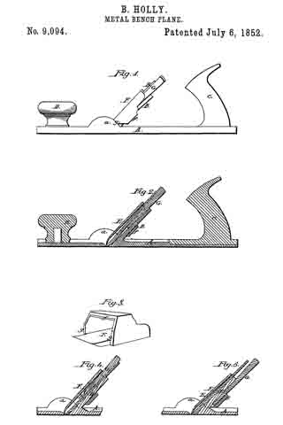
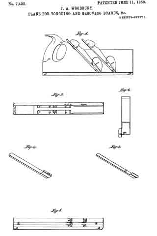
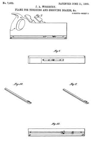
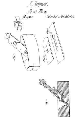
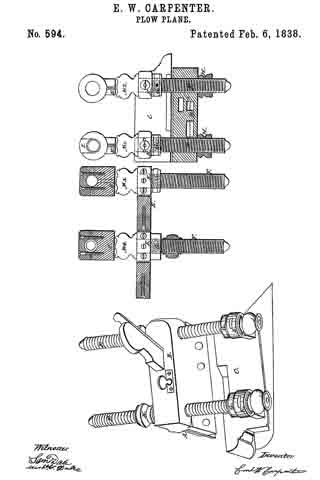
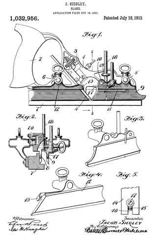
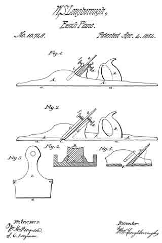
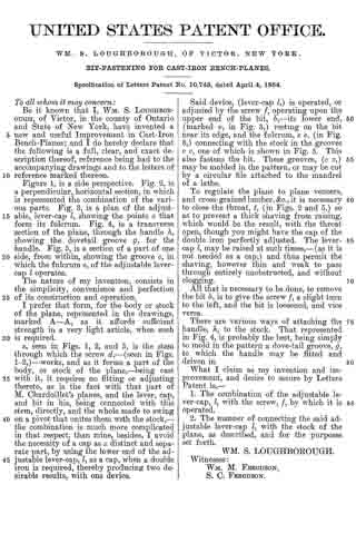
Figure 1, is a side perspective. Fig. 2, is a perpendicular horizontal section, in which is represented the combination of the various parts. Fig. 3, is a plan of the adjustable, lever-cap l, showing the points e that form its fulcrum. Fig. 4, is a transverse section of the plane, through the handle h, showing the dovetail groove g, for the handle. Fig. 5, is a section of a part of one side, from within, showing the groove c, in which the fulcrum e, of the adjustable lever-cap l operates.

The nature of my invention, consists in the simplicity, convenience and perfection of its construction and operation. I prefer that form, for the body or stock of the plane, represented in the drawings, marked A–A, as it affords suficient strength in a very light article, when such is required.

s, seen in Figs. 1, 2, and 5, is the stem through which the screw d, — (seen in Figs. 1-2,) — works, and as it forms a part of the body, or stock of the plane, — being cast with it, it requires no fitting or adjusting thereto, as is the fact with that part of M. Chardoillet’s planes, and the lever, cap, and bit in his, being connected with this stem, directly, and the whole made to swing on a pivot that unites them with the stock, — the combination is much more complicated in that respect, than mine, besides, I avoid the necessity of a cap as a distinct and separate part, by using the lower end of the adjustable lever-cap, l, as a cap, when a double iron is required, thereby producing two desirable results, with one device.

Said device, (lever-cap l,) is operated, or adjusted by the screw f, operating upon the upper end of the bit, b, — its lower end, (marked v, in Fig. 3,) resting on the bit near its edge, and the fuicrum, e e, (in Fig. 3,) connecting with the stock in the grooves c c, one of which is shown in Fig. 5. This also fastens the bit. These grooves, (c c,) may be molded in the pattern, or may be cut by a ciicular file attached to the mandrel of a lathe.

To regulate the plane to plane veneers, and cross-grained lumber, &c., it is necessary to close the throat, 25, (in Figs. 2 and 5,) so as to prevent a thick shaving from raising, which would be the result, with the throat open, though you might have the cap of the double iron perfectly adjusted. The lever-cap l, may be raised at such times, — (as it is not needed as a cap,) and thus permit the shaving, however thin and weak to pass tlgrough entirely unobstructed, and without clogging.

All that is necessary to be done, to remove the bit b, is to give the screw f, a slight turn to the left, and the bit is loosened, and vice versa.

There are various ways of attaching the handle, h, to the stock. That represented in Fig. 4, is probably the best, being simply to mold in the pattern a dove-tail groove, g, to which the handle may be fitted and driven in.

What I claim as my invention and improvement, and desire to secure by Letters Patent is —

1. The combination of the adjustable lever-cap, l, with the screw, f, by which it is operated.

2. The manner of connecting the said adjustable lever-cap l, with the stock of the plane, as described, and for the purposes set forth.

WM. S. LOUGHBOROUGH.

Witnesses:
WM. M. FERGUSON,
S. C. FERGUSON.

No. 9,094 – Hand Plane (Birdsill Holly) (1852)

[paiddownloads id=”11″]9094


UNITED STATES PATENT OFFICE.

_________________

BIRDSILL HOLLY, OF SENECA FALLS, NEW YORK.

HAND-PLANE.

_________________

Specification of Letters Patent No. 9,094, dated July 6, 1852.

_________________

To all whom it may concern:

Be it known that I, BIRDSILL HOLLY, of Seneca Falls, in the county of Seneca and State of New York, have invented certain new and useful Improvements in Metal Bench-Planes; and I do hereby declare that the following is a full, clear, and exact description of the same, reference being had to the accompanying drawings, forming part of this specification, in which —

Figure 1, is a side view of a cast iron bench plane with my improvements. Fig.
2, is a longitudinal section of the same. Fig.
3, is a perspective view of the cap. Figs. 4 and 5 are sections of parts of the plane showing the iron, wedge and cap in different positions.

Similar letters of reference indicate corresponding parts in each of the several parts.

The nature of this invention consists, 1st, in certain improvements in the stock and in the cap of the iron which allow the width of the throat to be altered for different kinds of work; 2nd, in certain means by which the cap of the iron is always caused to drop into its place without requiring any adjustment or setting.

To enable those skilled in the art to make and use my invention I will proceed to describe fully its construction and operation.

A, is the stock which consists of a cast iron plate with the stem B, standing up from it at a suitable inclination, and with two projecting pieces, a a, one on each side close in front of the stem. The stem B, is of about the same width as the plane iron and is made of tapering thickness, being rather smaller at the top. The two projecting pieces a a, are of nearly semicircular form and are of such width or thickness, or are at such a distance apart as to allow the plane iron and cap to slide freely between them. The stock is furnished at the back part with a handle C, similar to a common plane handle, and in front of the throat with a knob D.

The plane iron E, is similar in its general character to the iron of a common plane. The cap F, consists of a cast iron plate similar in form to the cap of a common plane iron, but it has a loop f, which is of sufficient width and depth to lit over the plane iron, the stem B, and the wedge G, by which the iron is secured. The bottom parts of the sides of the loop at g, g, form shoulders fitting to the semicircular projecting pieces a, a, of the stock and are at such a distance from the lower edge of the cap that when they rest on the projections the edge of the cap will be just above or within the face of the plane and parallel transversely to it; the edge of the cap is chilled or hardened.

The plane iron E, is placed between the cap F, and the stem B, and the wedge may be inserted between the iron and the stem as shown in Figs. 1 and 2; between the cap and the iron as shown in Fig. 4; or between the back of the stem and the loop f, of the cap as shown in Fig. 5. The first arrangement gives a wide throat which is best for rough work; the second gives a very small throat suitable for planing hard wood or cross grained stud, or for finishing fine work; and the third gives a width of throat about half way between the widths given by the other two arrangements. The difference in the width of the throats is produced by the alteration of the inclination of the iron and cap.

The advantage of having the cap to drop at once with certainty to its place, will be admitted by all accustomed to the use of bench planes, as it dispenses with the necessity of measuring and setting required in the common arrangement; and the want of a simple and sure means of regulating the width of the throat is well known.

What I claim as my invention and desire to secure by Letters Patent, is

1. The loop f on the cap F, in combination with the plane iron E, and the stem B, of the stock in the manner substantially as described, to wit, the said loop fitting over or embracing the plane iron and stem and, allowing the iron to be secured between the cap and the stem by means of a wedge G, placed either between the back of the iron and front of the stem, between the front of the iron and the cap, or between the back side of the stem and back part of the loop, the three positions of the wedge forming three different widths of throat as herein explained.

2. Providing the cap F, with shoulders g, g, which when the cap is placed in the stock of the plane will fall on suitable resting pieces provided in or upon the stock substantially as described.

BIRDSILL HOLLY.

Witnesses:
CHAS. J. MCKEE,
PHILO COWING.

No. 8,796 – Double Plane Iron (Fordyce Beals) (1852)

[paiddownloads id=”10″]8796


UNITED STATES PATENT OFFICE.

_________________

FORDYCE BEALS, OF PITTSFIELD, MASSACHUSETTS.

DOUBLE-PLANE IRON.

_________________

Specification of Letters Patent No. 8,796, dated March 16, 1852.

_________________

To all whom it may concern:

Be it known that I, FORDYCE BEALS, of Pittsfield, in the county of Berkshire, in the State of Massachusetts, have invented new and useful Improvements in Double-Plane Irons; and I do hereby declare that the following is a full, clear, and exact description of the construction and operation thereof, reference being had to the accompanying drawings, and to the letters of reference thereon, it being a part of this specification, in which —

A is the iron, C a section of the cap, and B a dovetail slide or projection of cap.

The nature of my invention consists in an improved arrangement for connecting and adjusting the cap to the iron.

To enable others skilled in the art to make and use my invention I will proceed to describe its construction and operation.

I construct my plane irons of any desired width, thickness, or form, with the following exceptions: In the place of a screw bolt as now used I substitute a dovetail slide formed by an oblong projection with beveled edges, either forged, screwed, or riveted or fastened in some feasible way to inside of cap, as shown at B in accompanying drawings, this projection being placed in the slot made in iron, as shown at B, of corresponding width, and edges of corresponding angle or bevel brings the cap with ease and accuracy to a parallel position with iron and obviates the necessity of a bolthead or projection of any kind on the back side of iron.

Also my improvement consists in an elongation of a portion of the cap to the length or to nearly the length of the iron, the elongation being wholly upon one edge and nearly half the entire width, as shown at C in drawing. To make this arrangement convenient I remove a portion of the iron from the slot upward (the iron being in a working position) the entire thickness and one half or near one half its width, thus giving place for the elongated part of cap as shown at C.

I disclaim all contrivances, arrangements, or forms of cap or iron which together compose a double iron now in general use.

What I claim as my invention and desire to secure by Letters Patent is —

The new and improved mode of fastening and adjusting the cap to the iron by means of a projection and slot forming a dovetail slide giving new facilities for the operation; and also a level surface to the back of the iron; also the elongation of part of the width of the cap and its occupying the place of a removed part of iron, giving the operator new facilities in nicely adjusting cap to edge of iron without removing it from the stack, the same as herein described using for the purpose the aforesaid arrangements of parts or any other substantially the same and which will produce the same effects in like manner.

FORDYCE BEALS.

Witnesses:

JULIUS ROCKWELL,
JAMES D. COLTER.

No. 8,655 – Beveling Plane (Harrison W. Lewis) (1852)

[paiddownloads id=”8″]8655


UNITED STATES PATENT OFFICE.

_________________

HARRISON W. LEWIS, OF BATH, NEW YORK.

BEVELING-PLANE.

_________________

Specification of Letters Patent No. 8,655, dated January 13, 1852.

_________________

To all whom it may concern:

Be it known that I, HARRISON W. LEWIS, of Bath, in the county of Steuben and State of New York, have invented a new and useful Improvement in Beveling-Planes; and I do hereby declare that the following is a full and exact description of the same, reference being had to the annexed drawings, making part of this specification, in which —

Figure 1 is a front elevation; Fig. 2 is a central longitudinal section; Fig. 3 is an end view from the left; Fig. 4 represents the rear side of the guard, and Fig. 5 shows the form of one of the planing cutters.

This invention consists of a plane, or planing instrument, of peculiar form, and furnished with several peculiar devices, so as to be adapted to the purpose of forming at one operation, and with extraordinary accuracy, a double bevel upon the grooved edge of a stile or rail of a panel door.

The stock A of this plane, has a longitudinal groove in the center of the under side thereof; and the spaces between this groove and the sides of the stock, consist of two inclined planes (surfaces) a a, the two planes being at an angle of about eighty degrees with each other, or about fifty degrees (each) with the sides of the stock. The stock is furnished with two cutters B (see Fig. 5) the cutting edges of which conform to the obliquity of the plane surfaces a a, and are fastened by wedges (b) in the manner of common planing tools.

An adjustable vertical guide C passes through the stock between the two cutters, and is secured in the required position by a horizontal screw c; and in the bottom of the guide is a narrow horizontal groove to receive the back of the gage-bar D. This gage-bar extends the full length of the stock A, and the two ends thereof are bent upward, as shown at e e Fig. 2. The forward end of the gage-bar passes up through a vertical groove in left or forward end of the stock (or in a vertical plate attached to the end of the stock), and has a slot (i) through which passes a set screw a whereby the gage-bar is held in the required position. The rear end of the gage-bar enters a vertical groove in the right end of the stock, and is held fast by a set-screw r, which passes through a plate s which is attached to the right end of the stock.

Two horizontal guard-screws E E pass through the stock, near the two ends thereof; and each guard-screw is furnished with a nut F and a collar G, whereby the screws are adjusted in any required position. The front end, or head, of each guard-screw has a shoulder or downward projection t, to the bottom of which is attached one end of a guard-stock H; and to the rear side of the guard-stock, an adjustable guard I is attached by means of two set-screws u u, which pass through two vertical slots v v, (Fig. 4) in the guard, and extending through the guard-stock, the front ends thereof are furnished with thumb-screw nuts x x. The slots v have rebates in the sides thereof (see Fig. 4) to receive the square heads of the screws u, that the heads may not be prominent to the face of the guard.

When the grooved edge of a rail is to be beveled by this plane, the guard is so adjusted as to slide upon the face of the rail, while the bottom of the guide C slides within the groove of the rail; and the gage-bar is so adjusted as to come in contact with the bottom of the said groove when the rail is sufficiently beveled, and thus prevent the cutters from planing off too much.

What I claim as my invention and desire to secure by Letters Patent is —

1. The adjustable gage-bar (D) and the vertical adjustable guide (C), in combination with the double faced plane-stock, all constructed and relatively arranged as herein described.

2. The combination of the guard-screws (E) , guard-stock (F), adjustable guard (I), gage~bar (D), vertical guide (C) and plane-stock (A; the whole being constructed and arranged substantially in the manner and for the purpose herein set forth.

HARRISON W. LEWIS.

Witnesses:

JOHN L. SMITH,
RUFUS PORTER.

No. 8,503 – Bench Hand Plane (Benjamin F. Bee) (1851)

[paiddownloads id=”7″]8503


UNITED STATES PATENT OFFICE.

_________________

BENJAMIN F. BEE, OF HARWICH, MASSACHUSETTS.

PLANE FOR FINISHING GROOVES IN PATTERNS &c.

_________________

Specification of Letters Patent No. 8,503, dated November 11, 1851.

_________________

To all whom it may concern:

Be it known that I, BENJAMIN F. BEE, of Harwich, in the county of Barnstable, in the State of Massachusetts, have invented a new and Improved Mode of Confining and Adjusting the Irons of Carpenters’ Planes and Molding Tools; and I do hereby declare that the following is an exact description thereof, reference being had to the accompanying drawings, and to the letters of reference marked thereon.

The nature of my invention consists in introducing upon each side, in the throat of carpenters planes — (in molding tools in the center of throat) a metallic plate movable perpendicularly to the plane of the iron or cap: the two plates being connected by a metallic bar on which pressure may be produced by a lever, containing an adjusting screw acting upon the principle of the cam, by which screw the pressure upon the iron may be increased or diminished :– the foregoing apparatus to be used in connection with a set screw placed at the back of the iron, the head of the screw working in a slot near the top of the iron by which the iron may be adjusted with ease and delicacy, and retained in its position after adjustment.

To enable others skilled in the art to make and use my invention, I will proceed to describe its construction and operation:

I construct my plane in any of the known forms, with the exception of removing from the throat, that portion of wood usually left for obtaining the action of the wedge upon the iron. I introduce on each side of the throat, into grooves adapted to the purpose, a metallic plate as shown at A, in the accompanying drawings. These plates are perforated near the upper edge by a rectangular hole, through which by means of an oblong mortise leading from the side of the plane stock, I place a metallic bar B, of such length as to reach to the outside of each plate, and of such strength as to sustain the amount of pressure necessary, to confine the iron firmly to the stock. This pressure I produce by the lever C, turning upon the pin D, as a fulcrum, containing the set screw E, acting on the principle of the cam; by which the pressure may be graduated at the will of the operator, according to the circumstances of the several parts.

In molding tools but one of these plates are necessary, the screw E, acting directly upon the upper edge of the plate A. When the rectangular bar B, and the pin D, have been put in their respective places they are retained there, and kept from exposure by a metallic plate, or disk, secured to the stock by screws or otherwise.

In connection with the aforesaid apparatus, I use the set screw F, working in the nut G, placed at the back of the iron; the head of this screw being of such size and shape, as to project through a slot H, near the upper end of the iron, by means of which the iron I may be adjusted to any degree of rankness, and retained in its position after such adjustment.

Whenever the operator would remove the iron from the stock, for the purpose of sharpening, clearing, or whatever else; he places his thumb upon the knob K, by drawing which toward the fulcrum of the lever, the sliding catch L, is released from the dog M; the iron is then liable to be withdrawn, by raising the upper end, so as to clear it of the set screw F. The iron may be returned to its place by a counter process, and confined there by pressing upon the knob K, in such a manner, as to force the catch L, under the dog M; retaining the same degree of rankness as before removal, abating whatever may have been whetted or ground away, and susceptible of any subsequent adjustment by means of the set screw F.

What I claim as my invention, and derise to secure by Letters Patent; is —

The application to carpenters’ planes, and molding tools, of a new method of confining the iron, by a metallic apparatus, acting upon the principles of the lever and cam; in combination with the set screw for adjusting the same, as herein described; using for the purpose, the aforesaid contrivance or arrangement of parts, or any other substantially the same, and which will produce the same effects in like manner.

BENJAMIN F. BEE.

Witnesses:
WM. H. UNDERWOOD,
STEPHEN C. ELLIS.

No. 7,938 – Tonguing, Joining And Rabbeting Plane (John A. Fry) (1851)

[paiddownloads id=”6″]7938


UNITED STATES PATENT OFFICE.

_________________

JOHN A. FRY, OF EDINBURG, VIRGINIA.

TOOL FOR TONGUING, JOINING, AND RABBETING.

_________________

Specification of Letters Patent No. 7,938, dated February 18, 1851.

_________________

To all whom it may concern:

Be it known that I, JOHN A. FRY, of Edinburg, county of Shenandoah and State of Virginia, have invented a new and useful Tonguing Plane, and that the following is a full, clear, and exact description thereof, reference being had to the accompanying drawings, which make part of this specification.

The purposes of my invention are to make a tool by the use of which the workman may make tongues of different thicknesses, the same tool being capable of both tonguing and jointing the stuff, and to make the same tool answer the purpose of a rabbetlng plane. The tool might be called a combined jointing-tonguing and rabbeting plane. The advantage of such a tool is that boards or plank of different thicknesses may be tongued with one implement, and yet each may have a tongue out upon it of a thickness adapted to that of the plank. It also enables the workman to diminish the thickness of any tongue if found too thick for the easy putting together of his work. It also saves the trouble of keeping on hand or carrying about three distinct tools instead of one, to perform the three or four operations for which this implement is intended.

My plane is made of two distinct parts or bodies B and B’, Figures 2 and 3; wherein, Fig. 2, is an underside plan and Fig. 3 a top plan. These parts may, by turning back the screws s, s, and screwing up the nut N, N, on the screws S, S, be brought close together, closing up the space m m between the two bodies. When the bodies are thus brought together, the instrument may be used first to joint a board, which it will do if the adjustable guide or gage G, Fig. 2, be brought into the position indicated by the dotted lines, G’. This position it can take by slackening the set screws r r, and slipping the gage piece till the screws occupy the opposite ends of the slots o, o, to those where they are seen in the figure. The plane iron P’ will then serve as a jointing cutter to straighten the edge of the board before commencing the tonguing, the board resting on its edge for both operations.

When a tongue is to be cut, after jointing the board, the slide or gage G is restored to the position seen in the figure (2) or so nearly to it as is required by the thickness of the plank. The two bodies B, B’ may then be either kept close together or they may be separated apart to a distance required by the thickness of the tongue intended to be formed. If they be kept close together the thickness of the tongue will be that of the two half grooves P, P’, but if they be separated by the adjusting screws s s, and fixed by the set screws S S, then will the thickness of the tongue be increased by the distance m of the separation of the two bodies. At whatever distance apart the bodies are set the guide or gage G, sliding along the face of the board determines the breadth of out which shall be made by the cutter P. The cutters P and P’ are both set inclined not only backward from the vertical, but also horizontally from their inner to their outer edges respectively. By this arrangement of the irons the chips or shavings are, when tonguing, thrown outward on the two opposite sides of the plane. The place of discharge is seen at R, in the side elevation of the body B, Fig. 1. The cutters P and P’ are held in place by the oblique wedges W and W’ Figs. 1 and 3.

The cutters have each two edges, one across the end and one on the inner side, whereby the side of the tongue is smoothed at the same time that the wood is cut away on both sides of it to form the jointed shoulders of the tongue. The edges along the sides also serve the purpose of diminishing the thickness of a tongue already made when such diminution becomes necessary.

The handle of the plane is seen at H, Figs. 1 and 3. It is permanently attached to the body B, but its base Q Q (Fig. 3) extends beyond that body and makes a projection which enters a notch M M, in the upper part of the body B’, which notch and projection serve to give a support in a longitudinal direction to the body B’ while the set screws S S confine it laterally to the body B.

When the plane is to be used for rabbeting the body B’ is wholly removed and the set screws S S may be taken out. Then by sliding the guide G on the set screws r r, till the edge w w coincides with or lies over x x, it may be then fastened for the purpose of using the plane to joint a board previous to cutting a rabbet. The plane iron P is driven down till its cross edge comes nearly or quite through the oblique slot V. The edge of the gage G together with the vertical side of the notch P, then serves as the face of the jointer, and the jointing cut is made not by the cross edges but by the side edge of the plane iron P. With the implement having its gage and cutter in the positions just described the board is jointed on its edge while it lies upon its face or flat side, the bottom of the notch or rabbet p resting upon the upper corner of the board and guiding or sustaining the plane.

The board having been jointed, is rabbeted without removing it from the bench. For this purpose, the tool is prepared by sliding the gage G into the position represented by the plain lines in Fig. 2, and the plane iron is set with its cross edge nearly on a level with the line x x, descending only far enough below that level to make its cut.

It is then used to out the rabbet without changing the position of the board, from that in which it lay while being jointed.

From the foregoing description it will be seen that the gage G is brought into use in combination with the notch P and the side edge of the cutter P to form a jointer for a board resting on its face, in a situation to be rabbeted ; that it is combined with the cross edge of the cutter P and with the half groove p to form the rabbeting plane; that when combined with the cutter P’ and the body B’ it forms a jointing cutter to joint a board, set up edgewise in a position to be tongued, and finally that the same gage G in combination with the two bodies B and B’, and the two cutters P and P’, it forms the tonguing plane. The parts of the tonguing plane just specified, together with the parts hereinbefore specified for setting the bodies B and B’ asunder and retaining them in place constitute an adjustable tongue cutter, whereby tongues may be out of different thicknesses to suit the thickness of the stuff or the purpose to which it is to be applied.

Fig. 4 is a cross section through x x Fig. 3, exhibiting the bodies B and B’ the gage G, the fastening screw S and its nut N together with an elevation of the wedges W, W’, plane irons P and P’ and the handle H.

What I claim as my invention and desire to secure by Letters Patent is —

1. So making a jointing, tonguing and rabbeting plane that the jointing and tonguing of a board while resting on its edge, and also the jointing and rabbeting of it while it lies on its flat side may all be performed with one planing tool in the manner substantially as herein described, and for the purposes herein set forth.

2. I also claim making the tonguing hand plane in such a manner as to enable the workman to make therewith tongues of various thicknesses substantially in the manner herein set forth, whereby I prevent the necessity of providing different tools to tongue planks of different thicknesses.

3. I also claim in combination with a divided body or plane stock, the two cutters having each a cross-cutting and a side-cutting edge and the means substantially as herein described for adjusting the distance apart of the two cutters and bodies whereby the plane is made capable of dressing the sides of a tongue to any desired thickness and at the same time to cut the shoulders as herein specified.

4. I also claim in combination with the gage G the use of the body B’ and the cross edge of the cutter P’ to constitute a jointer to straighten the edge of a board preparatory to tonguing it and while resting on its edge in a situation to receive the tonguing.

5. I also claim the gage G in combination with the notch p and the side edge of the cutter P, acting as herein described, as a jointing plane to straighten the edge of a board or plank resting on its flat side, in a position to have a rabbet out in the manner substantially as herein set forth.

JOHN A. FRY.

Witnesses:
GEORGE A. GRUNDSTAFF,
ISAAC RULY.

No. 7,543 – Scraper Used By Cabinetmakers (Hiram Carver) (1850)

[paiddownloads id=”5″]7543


UNITED STATES PATENT OFFICE.

_________________

HIRAM GARVER, OF EDINBURG, VIRGINIA.

SCRAPER USED BY CABINETIVIAKERS.

_________________

Specification of Letters Patent No. 7,543, dated August 6, 1850.

_________________

To all whom it may concern:

Be it known that I, HIRAM CARVER, of Edinburg, county of Shenandoah, and State of Virginia, have invented a new and useful Improvement in Cabinetmakers’ Scraping-Tools, and that the following is a full, clear, and exact description thereof, reference being had to the accompanying drawings, which make part of this specification.

The scraper in common use is a plate of steel of any convenient size and generally of uniform thickness, like a piece of common saw plate. An edge of this plate having been made straight or slightly curved, convexly outward is burnished on the edge with a piece of polished steel so as to raise a slight ridge or feathering on each corner as seen at e, e, and e’, e”, Fig. 1. Such plate is, when used to smooth off furniture, coach bodies, panelings and other work requiring to be brought to a smooth surface, usually held by the workmen between the thumbs and fingers of his two hands, and with the top inclined from him is operated by pushing, while the lower inclined feathered corner scrapes the surface and removes the irregularities left by the plane. This mode of using the scraper is excessively fatiguing to the lingers and thumbs and without great strength cannot be long pursued, nor without great steadiness of hand can the work be made of uniform smoothness. To remedy these inconveniences, and to make the scraper a convenient and efficient tool I furnish the scraping plate A with a stock (B) in which it is set, and held fast by set screws (C) or other equivalent device. The stock-frame D is a little wider than the plate A, and the stock has a slot quite through it, allowing the plate to come above the upper edge, as well as to descend below the lower edge of the stock.

E, E’, are cross pieces of the stock frame connecting together the side pieces D, D’, D D’ (Fig. 2) through which passes the axis F F of the scraper stock, having screws cut on the ends to receive the nuts G, G.

Along the lower and inner part of the side pieces D, D, are offsets I, I, (Fig. 2) and in these are sloping cavities or notches H, H’, within which the ends of the stock B are placed. The stock is thus capable of moving on its axis about one eighth of a revolution, more or less, and of being adjusted to any required angle of inclination to suit the work. This “notch” is also formed for the purpose of allowing the position of the stock and scraping plate to be reversed, so that instead of presenting the feather edge e’ to scrape the surface, that on the opposite corner, e”, may be brought into a position to work.

With the stock situated as seen in the dotted lines Fig. 1, the operator grasps the tool by the two handles D’, and resting the other end of the stock frame on the friction roller R, brings the edge e’ in contact with the surface to be scraped and with a pushing force scrapes a thin film of the material from the surface to be smoothed.

The purpose of the nuts G, G, (Fig. 2,) is to fasten the stock temporarily in one or the other position with the degree of its inciination properly adjusted according as the feather edge e’ or e” is intended to be used in scraping. When e’ is used the tool is pushed in the direction indicated by the arrow, and when B is reversed and brought toward a contact with the slope H, the operator takes the tool by the two handles D, D, and pushes in the direction opposite to that of the arrow, which brings the edge e” into action, and the forward end then rests on the friction roller R’.

I shall sometimes make two or more sides of the scraping plate capable of acting as scraping edges as e, e, and e’ e”, and shall form the outline variously, either straight, convex or concave, so as to adapt it to either plane convex or concave surfaces or to moldings of any kind which I may desire to smooth. Nor shall I confine the use of this tool to smoothing the surfaces of wood, but shall also apply it wherever found applicable, to scrape the surfaces of leather, horn, ivory, soft metals or any other solid substances requiring to be smoothed.

The rollers R, R’, prevent the scratching of the smoothed surface as well as guide the scraping edge. By the use of this roller the workman is relieved from the necessity of rubbing his hands upon the smoothed surface while sustaining the scraper as in the usual practice when holding it between his fingers.

What I claim as my invention and desire to secure by Letters Patent is —

1. The scraper stock set in a frame for holding and guiding the scraper so that the forward end only of the frame shall rest on the surface to be scraped and thereby enabling the workman to manage the tool with the whole hand, and apply a steady force; instead of using the fingers only as heretofore for that purpose.

2. I also claim reversing the position of the scraper stock and plate in the frame, whereby I am enabled to use both feather edges or corners of the plate successively without taking the plate from the stock as herein set forth.

HIRAM CARVER.

Witnesses:
WALTER R. JOHNSON,
JOHN B. STONER.

No. 7,432 – Plane For Tonguing And Grooving Boards (James A. Woodbury) (1850)

[paiddownloads id=”4″]7432


UNITED STATES PATENT OFFICE.

_________________

JAMES A. WOODBURY, OF BOSTON, MASSACHUSETTS.

PLANE FOR TONGUING AND GROOVING BOARDS, &c.

_________________

Specification of Letters Patent No. 7,432, dated June 11, 1850.

_________________

To all whom it may concern:

Be it known that I, JAMES A. WOODBURY, of Boston, in the county of Suffolk and State of Massachusetts, have invented certain new and useful Improvements in Apparatus for Tonguing and Grooving Boards, Planks, &c., and that the following description, taken in connection with the accompanying drawings hereinafter referred to, forms a full and exact specification of the same, wherein I have set forth the nature and principles of my said improvements by which my invention may be distinguished from others of a similar class together with such parts as I claim and desire to have secured to me by Letters Patent.

The figures of the accompanying plate of drawings represent my improvements.

Figure 1 is a side elevation of hand plane arranged with my improvements for cutting, or forming tongues in boards or planks. Fig. 2 is a top view of the same.

Fig. 3 is an isometrical perspective view of a gouge used in said plane, and Fig. 4 is a similar view of a smoothing chisel set behind this gouge in said plane; and Fig. 5 is a plan of the underside of said plane, and Fig. 6 is an end view of the same. Precisely similar views of a hand plane for forming grooves in boards or planks, to those represented in Figs. 1, 2, 3, 4, 5 and 6, are shown respectively in Figs. 7, 8, 9, 10, 11 and 12.

As the implements for forming tongues and grooves are now arranged, there is but a single cutting chisel of the ordinary shape or construction, the edge of which penetrates into the wood, and tears out the shaving from the sides of the groove or tongue, and leaves said sides rough and imperfect. While in cross-grained lumber and wet wood it is almost impossible to form a tongue or groove with the tools now in common use.

The defective operation of the tools heretofore devised, in the particular above noted, has long been sought to be remedied, and by my improvements the difliculties and imperfections above referred to are entirely obviated.

In my improved apparatus I use two cutting tools or chisels. That which first enters the wood is a gouge-cutter with a semi-circular cutting edge, which operates to take out the greater portion of the shaving required to be removed from the groove, or on each side of the tongue. And behind this gouge cutter is set a smoothing cutter havlng a common chisel edge at the bottom, and on each side thereof a cutting or face, the chisel edge operating to smooth the bottom of the groove &c., and the cutting lips serving to smooth the sides of the grooves and tongues.

The two hand planes shown in the drawings, are constructed in most respects, in the plane stocks, like those in common use for forming tongues and grooves. The handles of both stocks are shown at a a–a a, Figs. 1 and 7, and the guiding ledges which fit against the face of the boards or planks, are shown at b b–b b, in said figures, and in Figs. 5, 6, 11 and 12. They are both also contrived in the usual way, with the wooden wedges, c c c &c., Figs. 1 and 2, 7 and 8, for confining the cutting tools in proper position. The plane for forming the tongue has two sets or series of gouges and smoothing chisels, above referred to, as shown at d, e–d, e, Figs. 1, 2 and 5, and two throats, f f–g g, on each side for the delivery or escape of the shavings, as shown in said Figs. 1 and 2. It also has the usual groove, h h, Figs. 5 and 6, on its under side, which fits, and plays over the tongue as it is made.

The grooving plane requires discharging throats but on one side, and has the usual tongue, i i, Figs. 7, 11 and 12, along its under side through which the cutting tools pass, and which fits into, and plays through the groove, as it is made deeper and deeper in the board or plank.

As before suggested, and explained, the main feature of my invention consists in the use of gouges, d–d, in the tonguing plane, and k, in the grooving plane, to precede a smoothing tool, e–e and l, in said tonguing and grooving planes respectively; the said smoothing tools having lips to cut smoothly on the sides of the grooves and tongues to be formed. The gouges, d–d and k, have semi-circular cutting edges, and should be so set in the plane stocks, see Figs. 1 and 5, 7 and 11, as that the corners should penetrate into, and engage with the wood first, so as to turn the shavings up into the discharging throats freely. The smoothing irons in the tonguing plane have but one smoothing lip or face, as shown at m, Figs. 4 and 5, there being two such tools the front or cutting edge of the lip of one of which cuts on each side of the tongue, while the grooving plane has but one such tool, with a lip, n–n, on each side, the front or cutting edge of which serves to smooth each side of the groove. The smoothing tools which are set behind the gouges in both plane-stocks, shown in the drawings, should, like the gouges, to be so fixed in position, as the upper corners of the front or cutting edges of the side lips, m–n, n, shall first engage with, and penetrate the wood, as, by thus arranging them a “drawing stroke,” (so to speak,) is produced, as the planes are moved along, and the shavings, as before suggested, are more freely discharged through the throats formed in the stocks for the purpose.

It will be evident to any mechanic versed in the arts of carpentry or joinery, that the arrangement of tools for forming tongues and grooves hereinabove suggested, and described, may be used in stationary positions in a manner which will be readily understood, on the sides of power planing machines; or a series of alternate gouges smoothing cutters constructed as above described, may be set in a revolving frame or stock, and produce a much improved result on that which is now effected in such machines. A sufficient number of alternate gouges and smoothing cutters, should be used to out the tongue or groove of any required depth, by passing the board or plank once through the machine. The great end attained by any of the arrangements above described being the removal first by the gouges of the larger portion of the shaving, and then smoothing the sides and bottom of the grooves and sides faces of the tongues and the sunken or rebated edges adjacent to the same, by the smoothing tool, having the lips as described.

Having thus described my improvements, in tonguing and grooving apparatus, I shall state my claim as follows:

What I claim as my invention, and desire to have secured to me by Letters Patent in said apparatus, is —

The combination of a gouge or gouges, (for removing the bulk or greater portion of a shaving in forming tongues or grooves in boards or planks,) with smoothing tools having a chisel edge, a cutting and side lip on either or both sides thereof, (for smoothing the sides and bottom of the grooves, and the edges about the tongues, as set forth) ; said gouges being set in front of said smoothing tools, and the whole being arranged, and operating substantially, as hereinabove set forth.

Boston March 13th 1850.
JAMES A. WOODBURY.

Witnesses:
EZRA LINCOLN,
ROBERT L. HARRIS.

No. 6,459 – Bench Plane (Charles S. Beardsley) (1849)

[paiddownloads id=”3″]6459


UNITED STATES PATENT OFFICE.

_________________

C. S. BEARDSLEY, OF AUBURN, AND S. WOOD, OF NEW YORK, N. Y.

BENCH PLANE.

_________________

Specification of Letters Patent No. 6,459, dated May 22,1849.

_________________

To all whom it may concern:

Be it known that we, CHARLES S. BEARDSLEY, of Auburn, in the county of Cayuga, and SIMEON WOOD, of the city, county, and State of New York, have invented new and useful Improvements in Hand and Bench Planes, and that the following is a full, clear, and exact description of the principle or character which distinguishes them from all other things before known, and of the manner of making, constructing, and using the same, reference being had to the accompanying drawings, making part of this specification, in which —

Figure 1 is a side elevation of a hand plane on our improved plan; Fig. 2, a longi-tudinal vertical section; and Fig. 3, a cross section.

The same letters indicate like parts in all the figures.

In the hand plane as heretofore and now universally used the entire surface is on the same level, and the bit or cutting edge projects beyond it to the extent of the thickness of the shaving intended to be cut, the consequence of this is that the forward part of the surface of the plane can rest on the surface of the board forward of the shaving for that constitutes the gage to determine the thickness of shaving to be cut; but back of the cutting edge the surface of the board is reduced below the level of the forward part to the extent of the thickness of the shaving cut while the surface of the plane back of the cutting edge is on the same level with the forward part, and therefore if the back part of the plane be borne down it must be depressed and only rest on the planed surface at the back edge instead of along its entire length. The rear part, which runs on the planed surface, should be the guide to direct the plane, and for this purpose should have its whole surface running on the board and the forward part should only act as a gage and should therefore be on a higher level; but with the construction of the common plane this is not possible for the reasons mentioned.

The object of our invention is to avoid the defect of the common plane, and to this end the nature of the iirst part of our invention consists in making the surface of the plane from the cutting edge back on a level with the cutting edge, and the surface forward of the cutting edge parallel with the rear part, but movable and adjustable that it may be set so much above the level of the rear part as to determine the thickness of the shaving to be cut and constitute a gage for this purpose, and thus permit the entire surface of the plane back of the cutting edge to rest and run on the planed surface while the forward part or gage runs on the part from which the shaving has not been cut. And our invention also consists in making one surface of the planing bit or cutter the rear part of the surface of the plane, when this is combined with the making of the rear part of the stock, from the throat of the plane to the back, hollow for the passage and discharge of the shavings.

In the accompanying drawings (a) represents the stock of the plane which is made of iron and hollow. It is provided at top with a handle (b) in the usual manner, and the forward part is provided with these screws (c, c) and (d), the two (c, c) are tapped into a projection (e) of a gage plate (f) so that by the turning of these screws the gage plate will be elevated, and the other screw (d) is tapped into the stock and its end bears on the top of the projection (e)
for the purpose of forcing it down. In this way the gage plate can be regulated and set with accuracy. The side edges of the gage plate are adapted to slide freely and accurately within the hollow stock, and the rear edge which should be made at right angles with the sides of the stock, is so formed as to constitute, when in place, the continuation of a partition plate or flanch (g) which connects the two sides of the stock, and the rear face of this partition or flanch is inclined back toward the rear of the stock and gradually looses itself in the top plate of the stock which then runs horizontally to the back end. This forms what takes the place of the forward face of the throat of the ordinary plane.

The sides (h, h) of the hollow stock, inside and near the lower edge are grooved to receive the plane bit or cutter (i) which is a flat plate of metal, with the lower face perfectly true and parallel with the face of the gage plate while its upper face is parallel with the under face except at the forward end (j) where it is beveled down to form the cutting edge. This bit or cutter is thus inserted by sliding it in the grooves of the stock until the cutting edge is brought so near the rear edge of the gage plate as to form the throat of the plane for the passage of the shavings. In this way the throat is formed by the rear edge of the gage plate the flanch and the bevel of the bit or cutter, and the continuation of this throat for the delivery of the shavings at the rear is formed by the hollow stock. The lower edges of the sides of the stock should be chamfered off slightly in an upward direction at the sides of the cutting end of the bit, and then run to the forward end so much above the level of the face of the plane as to be above the greatest height to which the gage plate may be set for the greatest thickness of shaving. The under face of the gage plate should be parallel with the face of the plane back of the cutting edge but this is not indispensable. The planing bit may be inserted in the stock in any other manner as this does not constitute an essential part of our invention, and so of the gage plate it may be connected with the stock in any other desired manner, as for instance, it may be provided with projections at the sides fitted to slide in inclined grooves in the cheeks of the stock, and provided with a set screw to move toward or from the cutting edge of the bit, the inclination of the grooves having the effect to depress or elevate it while at the same time it reduces or increases the size of the throat.

The first part of our invention may be applied without the second by making the surface back of the cutting edge a part of the stock and inserting a separate bit, which may be done either by making a mortise through the sides or cheeks of the stock, or by inserting the bit and making the throat in the usual manner.

It will be obvious to those acquainted with the art of making and using planes that our improvements are applicabie to all kinds of hand planes for plain and ornamental work, the same construction and arrangement being applicable to all varieties, and the variations required being simply in the form.

We claim:

Constructing and applying the bit or cutter, substantially as described, that its lower surface may constitute that part of the surface of the plane back of the cutting edge, in combination with the hollow stock for the passage and delivery of shavings, substantially as described.

CHARLES S. BEARDSLEY.
SIMEON WOOD.

Witnesses:
A. P. BROWN, Sr.,
A. E. PETERS.

No. 6,304 – Plane For Bevel Edges (William H. Blye) (1849)

[paiddownloads id=”2″]6304


UNITED STATES PATENT OFFICE.

_________________

WILLIAM H. BLYE, OF DE RUYTER, NEW YORK.

PLANE FOR BEVEL EDGES.

_________________

Specification of Letters Patent No. 6,304, dated April 10, 1849

_________________

To all whom it may concern:

Be it known that I, WILLIAM H. BLYE, of De Ruyter, in the county of Madison and State of New York, have invented a new and useful Improvement in Planes for Working in Wood, of which the following is a full and exact description, reference being had to the annexed drawings of the same, making part of this specification, in which —

Figure 1 is a perspective view, Fig. 2. is an end elevation, and Fig. 3 is a view of the graduating arm or brace, and the guard plate, which secures the same to the end of the plane stock.

The same letters refer to the same parts in all the figures.

The nature of my invention, and improvement consists, in attaching an adjustable hinged guard or fence, to rabbet, fillister, molding, or other planes, by means of which the workman is enabled to bevel the edges of a piece of wood, in a uniform manner, and at any given angle.

In the accompanying drawings (a) represents the plane-stock which is made of wood, and of any required form and size.

(b) is the plane iron, (c) the wedge, which holds the iron in its place, (d) the guard or fence, is of the same length as the stock, and has one plane side which is about the same width as the face of the plane. From its uipper edge a rib (d2) is placed, for the purpose of stiffening the guard, and supporting the outer end of the braces, the outer, and under side of the rib and the lower edge, and back of the guard, may be ornamented with moldings, as represented, or otherwise, or may be left plain, according to the taste of the constructor: this guard is joined to the stock by hinges (e, e) which allow it to turn through an arc of about 100°, which admits of sufficient variation for most purposes, but in any case where greater variation, in the adjustment may become necessary, the hinges, and other parts concerned, can be so constructed, and arranged, as to allow the guard to turn through a longer arc. The braces (g) are of metal, and in the form of segments of a flat ring whose center is the axis of the hinge, the outer end of these braces have slots in them, through which the thumb screvv (h passes into the ends of the guard, to clamp it to the brace, these slots, also admit of the guard being turned to any extent within the limits of their length, to change the angle at which it stands to the face of the plane, and when the slots are too short, to admit of all the variation required, the ends of the braces are drawn out of the hole, formed in the end of the plate (i) and in the wood under the plate, and when placed in the proper position they are clamped firmly by the thumb screws (k k). Graduated scales of degrees may be formed upon the braces to denote the angle at which the guard may be placed.

The several parts of the plane above described may be made of wood, or metal, and arranged in a great variety of ways, without departing from the principle. of the invention, but these several modes, consist of devices well known to mechanics, and I therefore deem it unnecessary here to describe them.

The operation of this plane, is similar to that of others, the guard being adjusted to the required angle, is placed against the side of the piece, and held there firmly while the face of the plane is applied to the edge of the piece of wood, being pressed down upon it and at the same time pushed forward, the edge of the iron penetrates the wood to the depth which it projects through the face of the plane, and removes a shaving of that thickness — this operation is repeated until the piece is reduced to the required form.

What I claim as my invention and desire to secure by Letters Patent is,

The manner herein described of planing the edges of pieces of wood of a beveled form at given uniform or varying angles, by means of an adjustable guard hinged to the plane stock.

In testimony whereof I have hereunto signed my name.

WILLIAM H. BLYE.

Witnesses :
Z. T. BENTLEY,
A. V. BENTLEY.

No. 6,226 – Plane Iron Adjustment (Emanuel W. Carpenter) (1849)

[paiddownloads id=”1″]6226


UNITED STATES PATENT OFFICE.

_________________

E. W. CARPENTER, OF LANCASTER, PENNSYLVANIA.

ADJUSTING THE POSITION OF PLANE-IRONS AND REGULATING THE THROATS OF PLANES.

_________________

Specification of Letters Patent No. 6,226, dated March 27, 1849.

_________________

To all whom it may concern:

Be it known that I, EMANUEL W. CARPENTER, of Lancaster city, in the county of Lancaster and State of Pennsylvania, have invented a new Improvement in the Regulation of the Mouths in Planes so as to Enlarge or Diminish the Same and for the Preservation of a Close Mouth in Planes; and I do hereby declare that the following is a full, clear, and exact description of the construction and operation of the same, reference being had to the annexed drawings, making a part of this specification.

The object contemplated by my improvement, is the regulation of the mouth in planes, so as to enlarge or diminish the same; and for the preservation of a close mouth in planes.

To enable others skilled in the art to make and use my invention, I will proceed to describe its construction and operation, as follows, viz.:

A is a bench plane with the improvement.
B represents the wedge or key, with a. longitudinal aperture, over which is a scutcheon, inlaid with a similar aperture but not so wide, leaving room for the head of the screw to rest upon, (or by a washer or plate, as shown in the key in the double bit) for the purpose of fastening the key to the upper part of the bed of the plane, under the bit, by means of which the mouth of the plane can with ease be tightened by gently driving the key downward, or with equal ease enlarged, by drawing back the same.

The improvement is applicable to all kinds of planes.

The wedge or key in the double-bit plane is similar to that in the single-bit, with the exception of the opening left below the longitudinal aperture to receive the head of the screw that fastens the cap to the bit. A washer or plate is here used instead of the scutcheon as in the single-bit, to show its application, but the scutcheon is equally applicable.

C, is the molding plane, with the improvement. The wedge or key in the molding plane, is shaped like the bit, but the key part somewhat longer, and tapered down to the face of the plane; the bed of which, is out to suit the bevel or shape of the key B. The screw is here inserted at the upper side of the plane, to keep the key B, permanent while setting the bit.

What as I claim as my invention, and desire to secure by Letters Patent is —

The regulation of the mouth in planes, so as to enlarge or diminish the same, and for the preservation of a close mouth in planes, as herein described, by a wedge or key (B)
being placed under the bit, and fastened by a screw.

E.W. CARPENTER.

Witnesses:
W. WHITESIDE,
P. DONNELLY.

No. 5,620 – Joiner’s Plane (William A. Cole) (1848)

[paiddownloads id=”22″]5620


UNITED STATES PATENT OFFICE.

_________________

WILLIAM A. COLE, OF NEW YORK, N. Y.

JOINER’S PLANE.

_________________

Specification of Letters Patent No. 13,957, dated December 18, 1855.

_________________

To all whom it may concern:

Be it known that I, WILLIAM A. COLE, of New York, in the county of New York and State of New York, have invented a new and Improved Plane for Planing Curve or Level Surfaces; and I do hereby declare the following to be a full, clear, and exact description of the same, reference being had to the annexed drawings, making a part of this specification, in which —

Figure 1 is a side elevation of the plane. Fig. 2 is an end view.

Similar letters refer to similar parts, in both figures.

The nature of my invention, consists in an improvement in the construction of the plane, by which I am enabled to curve the face of the plane either concave or convex, and regulate the face of the said plane so as to plane various curves with the same plane.

In making my improvements I take an ordinary plane, with the plane irons, &c., as usual, I then cut a convex face upon it as seen at (a–b). To the face thus prepared I attach a plate of metal (c), at the center, the length and width of the plane; at the center there is a slot cut across through which the edge of the cutting iron may pass. At each end of the plate (c) there is a slide (d) connected, which passes up against the front and back of the plane, beneath a plate of brass, space being left sufficient to allow it to pass up and down.

In operating this plane, the face plate (c) is set to the desired curve, by pushing the pieces (d) down, these are then confined in their places, by a screw (e) upon the ends of the plane as represented. It will be seen that concave and convex surfaces can be planed by this instrument, and that it can be adjusted to any desired curve, as set forth and described above.

What I claim as my invention and improvement, and desire to secure by Letters Patent, is —

The adjustable metallic spring plate, secured to the face of the plane for the purpose of planing with one plane, various curves either concave or convex, substantially as herein described and set forth.

WM. A. COLE.

Witnesses:
A. W. KELLOGG,
I. P. PIRSSON.

No. 5,486 – Joiner’s Plane (Benjamin F. Shelabarger) (1848)

[paiddownloads id=”21″]5486


UNITED STATES PATENT OFFICE.

_________________

BENJ. F. SHELABARGER, OF MIFFLINTOWN, PENNSYLVANIA.

JOINER’S PLANE

_________________

Specification of Letters Patent No. 5,486, dated March 28, 1848.

_________________

To all whom it may concern:

Be it known that I, BENJ. F. SHELABARGER, of Mifflintown, in the county of Juniata and State of Pennsylvania, have invented a new and useful Improvement in Planes for Working Lumber ; and I do hereby declare the following to be a full, clear, and exact description thereof, reference being had to the accompanying drawings, making a part of this specification.

The nature of my invention consists in combining an adjustable metallic throat piece, with a plane iron and stock, in such a manner that the discharging aperture for the shavings will not be rendered imperfect or enlarged by the wearing away of the plane stock.

In the accompanying drawings Figure 1, is a vertical longitudinal section of a plane having my improved adjustable throat piece, combined with the same, and Fig. 2, is a perspective view of the throat piece detached.

A, is the plane stock.
a is the adjustable throat piece.
b, is the plane iron.
c, is a set screw, securing the plane iron to the throat piece.
e, is a slot in the plane iron, through which the screw c, passes.
d, is the tightening wedge, which secures the plane iron and throat piece within the plane stock.

The throat piece has a bearing surface a’ at its lower end, between which and the front side of the plane iron there is a space for the shavings to pass between, and out through the aperture g, in the throat piece, into the enlarged discharging throat f, in the plane stock. The enlarged discharging throat f, descends to about one half the depth of the stock; from the bottom of this enlarged throat, there is carried down to the base of the plane, a mortise with parallel sides, just large enough to receive the adjustable throat piece with the plane iron attached to it. It will readily be perceived therefore, that the bearing surface of the throat piece in front of the cutting edge of the plane iron, can be adjusted, as the stock wears away, so as to be always on a line with the face of the plane stock. The aperture between the bearing surface a’, of the throat piece, and the plane iron, — for the passage of shavings, — will remain perfect and of the same size till the plane stock is worn out; when the throat piece may be placed in a new stock. The advantage of having a perfect shaped discharging aperture in planes for the escape of the shavings, is so apparent, and so well known by all who are familiar with the use of this tool, that it is not necessary to dwell upon the subject. With planes, as now constructed, the discharging aperture for shavings, immediately in front of the plane irons, is constantly increasing in size, by the wearing away of the base of the plane stock. My adjustable metallic throat piece perfectly obviates this difliculty. My adjustable throat pieces I intend to apply to planes of all shapes and descriptions; the bearing surface of the throat piece, in all cases to correspond with the face of the planes. The aperture g, in the throat piece, extends upward a suflicient distance to allow the shavings to escape freely into the space.

What I claim as my invention and desire to secure by Letters Patent, is —

The combination of an adjustable metallic throat piece, with the irons and stocks of planes of all descriptions, substantially in the manner and for the purpose herein set forth.

BENJAMIN F. SHELABARGER.

Witnesses:
R. BARNARD,
SAML. C. FORREY.

No. 4,576 – Fastening And Adjusting Plane Irons (Leonard Bliss) (1846)

[paiddownloads id=”20″]4576


UNITED STATES PATENT OFFICE.

_________________

LEONARD BLISS, OF TRUXTON, NEW YORK, ASSIGNOR TO SAML. T. JEFFERY, OF HORNER, NEW YORK.

FASTENING AND ADJUSTING PLANE-IRONS.

_________________

Specification of Letters Patent No. 4,576, dated June 16, 1846.

_________________

To all whom it may concern:

Be it known that I, LEONARD BLISS, of Truxton, in the county of Courtland and State of New York, have invented a new and useful Improvement in the Method of Securing and Adjusting Cutting Bits or Irons of Hand-Planes, and that the following is a full, clear, and exact description of the principle or character which distinguishes my invention from all other things before known and of the manner of making, constructing, and using the same, reference being had to the accompanying drawings, making part of this specification, in which —

Figure 1 is a longitudinal vertical section, and Fig. 2 a perspective view with part of the stock cut off. The same letters indicate like parts in all the figures.

The method of fastening plane bits or irons to their stocks (now generally used) is by means of a wedge which requires hammering to drive it in or draw it out which in a short time, injures the stock and dis-adjusts the set of the cutting edge. Various other devices have been suggested and essayed to avoid this difliculty, but they have so far all failed, either in consequence of complexity and cost or the occupying of too much room in the throat of the plane, and therefore impeding the discharge of shavings. But by my improvement, which is simple, cheap, and not liable to derangement, I avoid all these difficulties; it consists in the employment of an eccentric metallic roller which has its bearings in the sides of the throat of the stock, and is situated immediately over the bit or iron, so that by turning it, the bit is either liberated or fastened; its diameter is so small as not to afford the least obstruction to the free discharge of the shavings; and by the turning of this eccentric to fasten the bit, if it be turned in the direction of the cutting edge it will tend to set for the cutting of a thicker shaving, and by turning it the other way the reverse effect will be produced.

In the accompanying drawings, (a) represents a wooden plane stock of the usual construction, having a throat (b), and plane iron or bit (c) which may be either single or double. The bit rests on the inclined bed (d) of the throat, and is gripped or held against this bed, by means of the metallic roller (e), which crosses it about midway between the bottom and top of the stock, and is provided with eccentric journals (f f) fitted to and turning in metallic boxes (g) let into the stock of the plane.
The eccentric roller is turned by means of a metallic rod (h) which fits in the holes (i i) in the roller.

It will be evident from an inspection of the drawings, that the turning of this eccentric roller will liberate or secure the plane iron or bit and that by turning it in the direction of the arrow (toward the cutting edge) that the bit will be carried down, and set for a thicker shaving; and that by turning it in a reversed direction, the bit will be drawn up and set for a thinner shaving, so that by this means plane irons or bits can be set and secured in place, or liberated without the necessity of hammering as in the old method.

What I claim as my invention and desire to secure by Letters Patent is —

The method of securing and setting plane irons or bits by means of an eccentric roller extending across the face of the bit and turning in boxes in the cheeks of the stock, as herein described.

LEONARD BLISS.

Witnesses:
JOHN BOUTWELL,
GEO. W. BLISS.

No. 3,838 – Setting Bits In Bench Planes (Levi Sanford) (1844)

[paiddownloads id=”19″]3838


UNITED STATES PATENT OFFICE.

_________________

LEVI SANFORD, OF SOLON, NEW YORK.

METHOD OF SETTING BITS IN BENCH-PLANES.

_________________

Specification of Letters Patent No. 3,838, dated November 26, 1844.

_________________

To all whom it may concern:

Be it known that I, LEVI SANFORD, of the town of Solon, in the county of Cortland and State of New York, have invented a new and useful Improvement in the Construction of Joiners’ Planes, by Which the Irons Are Adjusted by Screws for More or Less Bite, which is described as follows, reference being had to the annexed drawings of the same, making part of this specification.

Figure 1 is a perspective view of the plane stock and irons, combined for use. Fig. 2 is a vertical longitudinal section of ditto. Fig. 3 is a perspective view of the right-angled iron containing the female screws, and fastened in the stock. Fig. 4 is a perspective view of the plane-iron. Fig. 5 is a perspective view of the cap.

The nature of my invention consists in securing to the back part of the throat of a plane stock S, by screws or otherwise, a right angled piece of metal A, which receives the screw B, for securing and setting the cap C, of the plane bit D, and a screw E, for setting the plane bit D, by which arrangement the bit can be set for a greater or less bite, without moving the cap.

D, Figs. 1 and 2, represents the plane bit with my improvement attached to it. A represents the right angled piece of metal to which the adjusting screws B and E are fixed.

B represents the screw which passes through the cap C, bit D and right angled iron A, from the face side of the cap C, where there is a broad head attached to the screw, by which the bit and the cap are firmly attached to the iron A. The broad head of said screw is shown at B, Figs. 1 and 2.

F F represents the holes through the iron A, by which said iron is fastened or secured to the plane stock, by means of common wood screws.

E represents the main screw by which the plane bit is adjusted for work.

The cap C and bit D are both perforated in the middle with longitudinal slots I, J, to allow them to be moved up or down in the throat of the stock S and over the shank of the screw B, that confines them to the iron A, fastened to the stock S, when the screw E is turned.

The upper corners of the end of the bit, projecting above the stock are cut off as in the common plane iron. A notch G, Figs. 1 and 2, is then made in this end of the bit in the middle thereof about half an inch deep and as wide as the diameter of the neck H of the screw E. This end of the bit is then bent down at right angles so as to enter the channel formed around the neck of the screw E will recede obliquely upward drawing with it the bit ; and by turning said screw in a contrary direction, or to the left, the screw and bit will descend obliquely in a contrary direction by which arrangment and mode of operation, the bite of the plane iron or bit may be increased or diminished at pleasure or adjusted with the greatest exactness without the use of wedges and mallet or hammer, and without moving the cap, the distance between the lower edge of the cap and the cutting edge of the bit being increased or diminished as the bite is increased or decreased. The cap and bit are otherwise made in the usual manner. Likewise the stock.

I am aware that a patent has been granted for a plane in which there is a piece of metal secured to the back part of the throat of the plane, to receive a screw, by which the bite of the bit is regulated, and I am also aware that a screw has been used for drawing cutting tools in and out at pleasure, to regulate the degree of bite, and therefore I do not claim these devices as my invention ; but

What I do claim as my invention and which I desire to secure by Letters Patent, is —

The arrangement herein described, by which the piece of metal at the backside of the throat, receives the screw that secures the cap C, embracing the bit D and also the set screw E, for the adjustment, and moving of the bit D, by which arrangement the said bit D can be set without moving the cap C as described.

LEVI SANFORD.

Witnesses:
EDWIN MAHER,
THOMAS WIBIRT.

No. 594 – Plow Plane Screw Arms (Emanuel W. Carpenter) (1838)

[paiddownloads id=”17″]594


UNITED STATES PATENT OFFICE.

_________________

EMANUEL W. CARPENTER, OF LANCASTER, PENNSYLVANIA.

METHOD OF CONSTRUCTING THE SCREW-ARMS FOR ALL KINDS OF PLANES REGULATED WITH SCREW-ARMS.

_________________

Specification of Letters Patent No. 594, dated February 6, 1838.

_________________

To all whom it may concern:

Be it known that I, EMANUEL W. CARPENTER, of the city of Lancaster, State of Pennsylvania, have invented a new and useful improvement in the mode of regulating plow-planes, tongue and grooves, fillisters, and such other planes as are regulated by screw-arms; and I do hereby declare that the following is a full and exact description.

That part of the arm to which the fence is attached (marke E in the drawing) I make of hard wood about an inch thick, one inch and seven eighths broad and about two and three fourths inches high. A hole is bored near its upper edge large enough to receive the screw part of the arm (letter F) which is kept to its place by means of a groove cut around the screw near its head and by a broad dowel (letter I) let into this groove from the top of the first described piece. Two screw holes are made through the body of the plane one near each end to receive the screw arms or male screws (F) ; then by turning these screw arms, by applying the power to their heads, you regulate the fence with the body of the plane, with ease and exactness, but to hold each more firmly to its place when regulated, a screw nut (G) is placed on each arm on the left side of the body of the plane and a larger one (H) on the right side and by screwing these up when the plane is set, to wit, by bringing the two on the right side close to the body of the plane and the two on the left side close to the upright (E) part of the arm, the fence is kept firm to its place during the working of the plane. A 2d method : In this arm, the dowel may be omitted, the screw nut (G) being brought close to the first described piece E and pinned fast through the screw arm. A 3d method is by having the arm to which the fence is attached, E, in two pieces, the lower piece to extend up to the center of the arm. A hole is made, one half in each of these pieces, a groove is cut, round, in the head of the screw arm sufficiently large to admit these pieces into it, these pieces are then fastened together with two iron screws. A 4th method differs from the last described, in boring the hole half through on the left side with one bit end and on the other with a larger bit and cutting the groove in the screw arm to fit this hole and then fastening the two pieces together with iron screws as in the last, this one like the first, has also a screw nut on the arm F to keep this part more firm.

What I claim as my invention and desire to secure by Letters Patent, is —

The method of making and applying the screw arms to the plane as described, which regulate the fence with great ease and accuracy and give it an increased firmness over all others now in use.

EML. W. CARPENTER.

Witnesses:
SAML. DALE,
MICHL. DALE.

No. 184 – Spoke Shave (Ira L. Beckwith) (1837)

[paiddownloads id=”16″]184


United States Patent Office.

_________________

IRA L. BECKWITH, OF QUINCY, MASSACHUSETTS.

IMPROVEMENTS IN SPOKESHAVES.

_________________

Specification forming part of Letters Patent No. 184, dated April 29, 1837.

_________________

To all whom it may concern:

Be it known that I, IRA L. BECKWITH, of Quincy, in the county of Norfolk and State of Massachusetts, have invented a new and useful improvement in a machine or instrument commonly called and known as a “Spokeshave;” and I do hereby declare that the following is a full and exact description.

In the accompanying drawings, the part numbered 5 represents the frame or wood-work, as seen in the accompanying model. It is of boxwood, but may equally well consist of any other kind of hard wood.

No. 1 in the drawings is a steel roller, fitted into No. 2, which is a sort of frame fixed to the wood and immovable. The roller is fitted in and is designed to turn with the greastest facility.

No. 2 is the frame set into the wood and serving to control the roller. It is generally (and always when in use) immovable; but it is made fast to the wood by two bolts, which enter on the front side at a and b and pass entirely through the wood, coming out at the opposite side, where they are fitted with a nut, which is screwed on the ends of the bolts, so that as the knife (marked 3) wears away by use and leaves too great a space between it (the knife) and the roller, the wood immediately behind the roller may be a little cut away, and then, by screwing on the nut, the roller with No. 2 will be approximated to the knife and may be used again.

No. 3 is the knife. It is a plate of steel. It is intended to be kept constantly sharp. It is fastened to the wood by two prongs or feet — one at either end of the knife — which pass through the wood and enter and are fixed in two thumb-screws on the opposite side.

No. 4 is a thin plate, stratum, or cap of steel, which is fitted immediately under and in close contact to the knife. It is made fast to the knife by two screws, (marked c and d.) The general object of this cap is to enable the instrument to be used against the grain of the wood which is being shaved, which cannot be done with the spokeshave now in use.

It will be observed that the holes or apertures in the cap for the entrance of the screws are somewhat larger than the body of the screws. The object in this is that as the knife wears away the screws may at any time be a little loosened and the cap slid back from the edge of the knife; then tighten the screws again and your instrument is ready for renewed use.

What I claim as my invention, and desire to secure by Letters Patent, is —

1. The substitution of the roller No. 1 for the square block of immovable metal in the old spokeshave, by which substitution the shavings are more freely shed, and wood, or a spoke of a more crooked or curved surface may be shaved.

2. The manner, as before described, in which the parts are put together so as to approximate the roller to the edge of the knife as the knife wears away.

3. The addition of the cap marked No. 4, which did not exist in the old spokeshave, and which gives tho wheelwrights and other mechanics the important power of shaving against the grain, and the manner in which the said cap is fixed to the knife so as to be moved back as the knife wears away.

IRA L. BECKWITH.

Witnesses:
A.CHURCHILL. Jr.,
H. H. FLANDERS.

No. 3,355 – Cast Iron Plane Stock (William Foster) (1843)

[paiddownloads id=”18″]3355


UNITED STATES PATENT OFFICE.

_________________

WILLIAM FOSTER, OF WASHINGTON, DISTRICT OF COLUMBIA.

CAST-IRON PLANE-STOCK

_________________

Specification of Letters Patent No. 3,355, dated November 24, 1843.

_________________

To all whom it may concern:

Be it known that I, WILLIAM FOSTER, of the city of Washington and District of Columbia, have invented a new and useful Improvement in Cast-Iron Plane-Stocks; and I do hereby declare that the following is a full, clear and exact description thereof; reference being had to the accompanying drawings, which form a part of this specification, in which —

Figure 1, is an isometrical view showing the under side of the plane, or face; Fig. 2, vertical section.

The nature of my invention consists in forming a recess in the face of the plane stock, into which an adjustable piece of soap stone, or other suitable material is inserted and regulated by a screw.

The face (a) of the plane stock is oblong and true, and of the usual form of wooden plane stocks, but only sufficiently thick for strength; from each side flanches (b) rise, while at the point where the plane iron is inserted is as high as a common wooden stock, from them they gradually taper off to each end. A slit (c) is cut across the face through which the plane iron projects, and just forward of this there is a recess (d) into which a piece of soap stone (e) or other suitable material or substance is put, the projection of which is regulated by a screw (f) above, this forces it out as it wears away. Grooves are cast on the sides of the plane stock, inside from the throat up to the top to hold the plane iron and wedge; behind them is a socket projecting up from the inside of the face to hold the handle, which is made from wood in the usual way ; before the recess (d) occasions the plane to run light and easy, thus rendering it the most efficient plane stock made for durability, economy and convenience. The recess (d) may be formed if desired before the socket (h) instead of behind as before explained and described.

Having thus fully described my cast iron plane stock, what I claim as new and desire to secure by Letters Patent is —

The recess (d) formed in front of the plane iron, or of the forward handle, in the face of the cast iron plane and filled with soap stone or other suitable material, which is regulated by a screw substantially in the manner, and for the purpose herein explained.

WILLIAM FOSTER.

Witnesses:
J. J. GREENOUGH,
L. CALDWELL.

No. 1,032,956 – Plow Plane (Jacob Siegley) (1912)

[paiddownloads id=”67″]1032956


UNITED STATES PATENT OFFICE.

_________________

JACOB SIEGLEY, OF WILKES-BARRE, PENNSYLVANIA, ASSIGNOR TO STANLEY RULE & LEVEL COMPANY, OF NEW BRITAIN, CONNECTICUT, A CORPORATION OF CONNECTICUT.

PLANE.

_________________

1,032,956. Specification of Letters Patent. Patented July 16, 1912.

Application filed October 18, 1911. Serial No. 655,361.

_________________

To all whom it may concern:

Be it known that I, JACOB SIEGLEY. a citizen of the United States, residing at Wilkes-Barre, Luzerne county, Pennsylvania, have invented certain new and useful Improvements in Planes, of which the following is a full, clear, and exact description.

My invention relates to planes, particularly of the kind known as router or beading planes, which are adapted for beading, matching or rabbeting.

The object of the invention is to provide an improved construction in which the mouth of the planemay be easily freed of shavings; to provide an improved depth gage between the runners to determine the depth of a matched tongue or beading ; to provide improved means for steadying the parts of the adjustable runner, and to improve the structure of these planes generally.

With these objects in view, the invention consists in the construction and arrangment of parts, the preferred embodiment of which is illustrated in the accompanying drawings, in which —

Figure 1 is a side elevation of a plane embodying my improvements. Fig. 2 is a transverse sectional view on the the line 2–2 Fig. 1, looking toward the front. Fig. 3 is a perspective view of the forward section of the adjustable runner detatched. Fig. 4 is a view similar to Fig. 3 of the rear section of the adjustable runner. Fig. 5 is a fragmentary view of a plane iron showing the form of depth gage heretofore usually employed.

In the embodiment of my invention herein selected for illustration, 1 indicates the plane stock having the usual handle 2, and adjusting means designated generally by 3 for adjusting the plane iron 4. The stock is provided with the usual laterally extending supporting pins 5 and 6 upon which at one side of the stock is secured an edge guide 7. The stock, furthermore, is provided with a runner 8, usually integral with the stock and fixed relatively to the position of the plane iron. Upon the side of the stock opposite the runner 8 I provide a second runner, which in my improved construction consists of the forward section 9, which is mounted upon the forward supporting pin 5 and is steadied in position by steadying pin 10 extending laterally from the stock. This section of the runner may be provided with the usual depth gage 11 for beading or matching purposes. The rear section 12 of this two-part adjustable runner is mounted on the supporting pin 6, and the body of this section is provided at its forward end with a hook 13 arranged to extend over the plane iron 4 when the latter is in position, thus serving both as a steadying means for the forward end of the rear runner section 12 and as a steadying means for the plane iron.

In planes of this character as heretofore constructed, and for the purposes of determining the depth of the channel, bead or tongue to be cut, the plane iron, as 14, Fig. 5, is provided with a depth gage 15, adjustably mounted in a slot 16 of the plane iron by means of a screw 17, said slot 16 of course determining the depth in this case of a matching tongue to be formed. In my improved plane I dispense with a depth gage on the plane iron and mount a depth gage between the runners, as indicated in Figs. 1 and 2, in which 17 is the depth gage shoe, 18 the depth gage rod and 19 a clamp for holding said depth gage in adjusted position. By an inspection of Figs. 1 and 2 it will be seen that the range of adjustment of the depth gage 17 greatly exceeds that of the depth gage 15 on the plane iron as heretofore constructed. Furthermore, this depth gage may obviously be adjusted to required position without in any way disturbing the plane iron then mounted in the stock. The depth gage rod 18 has a suitable bearing against the side of the stock, so that as the clamp 19 is tightened by means of its thumb nut 20, the depth gage will be firmly held in adjusted position. This clamping means constitutes one of the features of my invention and comprises a head which surrounds the depth gage rod and a shank which extends through a suitable perforation in the stock upon the extremity of which shank the clamping nut is mounted so that the gage rod is drawn securely against the bearing face on the stock.

By reason of the independent mounting of the forward and rear sections of the adjustable runner, I dispense with the usual arch or bridge which unites the forward and rear portions of the adjustable runners now in use, so that the mouth of the plane is left entirely free for egress of shavings, whereby the plane iron is less likely to become clogged.

While I have herein described a particular embodiment of my invention, it is to be understood that the same may be altered in detail and relative arrangement of parts within the scope of the appended claims.

What I claim is:

1. In a bench plane, the combination with a stock having a fixed runner, of an adjustable runner spaced therefrom, a plane iron between said runners, means for attaching said adjustable runner to the stock, and means for simultaneously steadying said adjustable runner and said plane iron.

2. In a bench plane, the combination with a stock having a fixed runner, of an adjustable runner comprising a forward section, means for attaching said forward section to the stock, means for steadying said forward section in position, a rear section, means for mounting said section upon the stock, a plane iron supported between said fixed and adjustable runners and means for simultaneously steadying said rear section and the plane iron.

3. In a bench plane, the combination with a stock having a fixed runner, of an adjustable runner spaced laterally therefrom and comprising two separate sections independently and adjustably carried by said stock, and a depth gage extending between said fixed runner and the said adjustable runner.

4. In a bench plane, the combination with a stock having a fixed runner, of an adjustable runner comprising a forward section mounted on said gage stock and an independent rear section also mounted on said stock, said rear section having a hook at its forward end adapted to overlie and steady the plane iron at the same time to steady said rear section in operative position.

5. In a bench plane, the combination with a stock having a fixed runner, of a second runner comprising a plurality of independent aligned sections spaced laterally of said fixed runner, means for adjustably supporting said sections from the stock, and means independent of said supporting means for steadying each of said sections in position.

6. In a bench plane, the combination with a stock having a fixed runner, of a second runner spaced laterally therefrom and comprising independent forward and rear sections having their adjacent ends spaced apart to form a free and unobstructed plane mouth, means for adjustably supporting said sections laterally from the stock, and means independent of said supporting means for separately steadying each of said sections in position.

JACOB SIEGLEY.

Witnesses:
JOHN P. POLLOCK,
J.L. CAREY.

_________________

Copies of this patent may be obtained for five cents each, by addressing the “Commissioner of Patents, Washington, D. C.”
_________________

No. 17,111 – Adjusting And Holding The Knives Of Spokeshaves (Manley Packard) (1857)

[paiddownloads id=”39″]17111


UNITED STATES PATENT OFFICE.

_________________

MANLEY PACKARD, OF NORTH BRIDGEWATER, MASSACHUSETTS.

METHOD OF ADJUSTING AND HOLDING THE KNIVES OF SPOKESHAVES.

_________________

Specification of Letters Patent No. 17,111, dated April 21, 1857.

_________________

To all whom it may concern:

Be it known that I, MANLEY PACKARD, of North Bridgewater, in the county of Plymouth and State of Massachusetts, have invented a new and useful Iniproveinent in Spoke or Heel Shaves; and I do hereby declare that the same is fully described and represented in the following specification and the accompanying drawings, of which —

Figure 1, is a top view, Fig. 2, a rear elevation, Fig. 3, a transverse and central section, and Fig. 4, a longitudinal section of one of my improved articles.

In these drawings A, denotes the handle or stock of the shave; B, the curved cutter knife made in the usual manner with starts a, a, which when the knife is in place in the stock, extends in the usual manner, through holes or mortises made in the same. The cutting edge of the knife operates in connection with a metallic bearer rest b, arranged in front of it, the same constituting the front boundary of the throat c, through which the shavings escape when the tool is in use. So far as the above mentioned parts are concerned, the instrument does not differ from many other spoke shaves.

My improvement which has relation to a means of confining the starts in the stock consists not only in employing a bow spring C, to extend from one start to the other and rest on the upper side of the stock as shown in the drawings, but in having a screw D, to extend through the middle part of the said spring and screw into the stock, the head of the screw being in contact with the top surface of the spring. By screwing the screw into the wood, the bow spring will have its ends forced against the starts so as to hold them firmly in place, an abutment of metal, c’, being placed against each start and fastened in the stock, as shown in Figs. 1, and 4.

By the above described arrangenient and application of the bow spring and screw with reference to the stock and starts of the knife, the fixation of the knife in the stock, and at any distance from the bar b, is a matter which can be accomplished with ease and certainty, the knife not being liable to change its position after once having been adjusted. Besides this, the arrangement of the fastening contrivances, causes them to be so isolated from the sides of the stock as not to interfere with the operations of a workman, who may be using the instrument. The inner corner of each start is beveled or charnfered olf a little as shown at f, in order that when the starts are being driven or pressed through the stock, they may go clear of the ends of the spring so as not to injure it.

My improveinent is one of much utility, as while it affords a simple and efficient means of maintaining the knife in place in the stock it is not in the way of a workman as clamp screws are when extended into and from the sides of the stock.

I do not claim applying either a wedge or a clamp screw to each start in order to keep it in place in the stock, but

What I do claim is —

The above described new arrangement of the clamp screw and bow spring with respect to the handle and starts of the knife or cutter and so as to operate therewith substantially as specified.
In testimony whereof I have hereunto set my signature.

MANLEY PACKARD.

Witnesses :
MARSHALL M. PACKARD,
J. R. PERKINS.