| PLEASE NOTE: The images presented on this page are of low resolution and, as a result, will not print out very well. If you wish to have higher resolution files then you may purchase them for only $2.95 per patent by using the "Buy Now" button below. All purchases are via PayPal. These files have all been cleaned up and digitally enhanced and are therefore suitable for printing, publication or framing. Each zip package contains all the images below (some packages may contain more), and purchased files can be downloaded immediately. |
UNITED STATES PATENT OFFICE.
_________________
R. E. LOWE, OF UPPER ALTON, ILLINOIS.
IMPROVEMENT IN PLANES FOR CUTTING BLIND-SLATS.
_________________
Specification forming part of Letters Patent No. 82,424, dated September 22, 1868.
_________________
To all whom it may concern:
Be it known that I, R. E. LOWE, of Upper Alton, in the county of Madison and State of Illinois, have invented a new and Improved Rustic-Blind-Slat Plane; and I do hereby declare that the following is a full, clear, and exact description of the construction and operation of the same, reference being had to the accompanying drawings, making a part of this specification, in which —
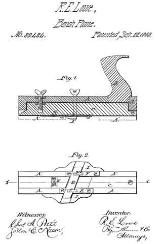
Figure 1 is a longitudinal vertical section through line x x of Fig. 2. Fig. 2 is a bottom view.
The object of this invention is to construct a simple and easily-adjustable instrument, by which the slats of which rustic window-blinds are made can be out out from the wood in an easy and expeditious manner. The instrument is so improved that the slats can be cut of different widths and thicknesses, while, if the plane becomes dull, it can be made to present a sharp edge again in a moment of time, without the necessity of removing it to be ground or sharpened.
In the drawings, A A’ is the stock; B, the handle, and C an adjustable shoe, held at the rear end by a screw, c, and held and adjusted at or near the forward end by a larger and stronger set-screw, c’, provided with a thumb piece or nut on the upper side of the stock. This shoe does not extend across the whole width ofthe sole of the stock, but lies in a groove or longitudinal depression in the latter, as seen in the bottom view, Fig. 2. The part A represents the body of the stock, A A’ representing a projecting flange along its left lower edge, which operates against the side or edge of the stick from which the slats are cut, and serves to guide the instrument.
D is the bit or cutter-iron, lying obliquely across the sole in a flat position upon two supporting-plates, E E, which are screwed to the stock, and itself being firmly held in position by two hooks, F F, the shanks of which pass through the stock and enter the screw-nuts G G on its upper side, just in front of the handle. The supporting-plates E E rest upon the stock, and neither they, nor the cutter-iron, nor the hooks F F are connected in any way with the shoe C, which lies under the cutter, as shown in Fig. 2. In consequence of this arrangement, when the shoe is adjusted up or down by means of the set-screw c’, the thickness of the slat that the iron will cut is perfectly controlled and regulated thereby. Strips of rubber may be placed under the ends of the bit, between it and the wood, to hold it more firmly. The width of the track between the projecting flange A’ and the opposite projecting hook F, between which the stick that is operated upon must be held, is such that a wide slat may be cut; or, by means of a splitting-gage, H, one or two narrow ones may be made.
In practical operation I usually construct the instrument so that it will, without the gage, cut a strip of one inch in width, or, with the gage, will cut two strips of half an inch each. Were the bit only of sufficient length to cut one strip, without the possibility of shifting it endwise, so as to bring anew cutting-edge or an unused portion of the same cutting-edge into operation when one part of the edge becomes dull, the workman would be obliged to take out the bit and sharpen it every time it lost its edge. I obviate this difficulty by making it of such length that it can be shifted endwise in either direction, so as to bring a fresh portion of the edge into operation. Practically I construct it so that it will cut a one-half inch strip at its center, and, when dull there, can be shifted half an inch either to right or to left. Its edge will hold without grinding, therefore, three times as long as if of the usual form.
In order to support and guard the projecting ends of the cutter-iron, I attach guards I I to the side of the stock, their under edge flush with the sole of the stock, and a groove or depression sunk obliquely across them to allow the longitudinal movement of the cutter-iron.
Having thus described my invention, what I claim as new, and desire to secure by Letters Patent, is —
1. The arrangement of the shoe G, stock A A’, screws c c’, cutter-iron D, and clamping-hooks and nuts F G, substantially as described, when the parts are constructed to operate in the manner set forth.
2. The arrangement of the guards I I with the knife D, the track C, and the gage H, constructed and operating substantially as described.
R. E. LOWE.
Witnesses :
C. W. LEVERETT,
J. B. HOVEY.


