
| PLEASE NOTE: The images presented on this page are of low resolution and, as a result, will not print out very well. If you wish to have higher resolution files then you may purchase them for only $2.95 per patent by using the "Buy Now" button below. All purchases are via PayPal. These files have all been cleaned up and digitally enhanced and are therefore suitable for printing, publication or framing. Each zip package contains all the images below (some packages may contain more), and purchased files can be downloaded immediately. |

United States Patent Office.
JOHN BLAKE TARR, OF CHICAGO, ILLINOIS.
Letters Patent No. 82,450, dated December 18, 1868.
_________________
IMPROVEMENT IN CARPENTERS’ PLANES.
_________________
The Schedule referred to in these Letters Patent and making part of the same.
_________________
TO ALL WHOM IT MAY CONCERN:
Be it known that I, JOHN BLAKE TARR, of Chicago, Cook county, State of Illinois, have invented an Improved Carpenters’ Plane; and I do hereby declare that the following is a full, clear, and exact description thereof, reference being had to the accompanying drawings, making part of this specification, in which —
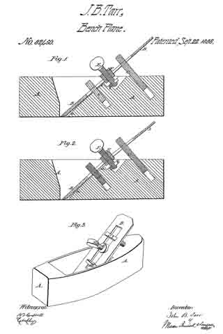
Figure 1 is a longitudinal section, taken vertically through the centre of my improved plane.
Figure 2 is a similar view of the same parts, showing the plane-iron set to cut a very thick shaving.
Figure 3 is a perspective view of the plane complete.
Similar letters of reference indicate corresponding parts in the several figures.
This invention relates to an improvement in adjusting and setting plane-irons of carpenters’ or bench-planes, of various descriptions, whereby these irons or blades can be adjusted and set at any desired pitch for removing very thin or very thick shavings, by simply turning a thumb-screw, which is applied to the plane-stock and blade in such manner as to give a greater or less bow or bend to the latter, according to the pitch required, as will be hereinafter described.
Before my invention, plane-irons have been applied to plane-stocks by means of clamping-devices, which bent or bowed the irons, so as to increase or diminish the pitch of their cutting-edges for removing thick or thin shavings. The objection to said devices is, that it is necessary to render the plane-irons comparatively loose in adjusting their cutting-edges for removing thick shavings. The object of my invention is, to so construct and apply adjusting-clamps to plane-irons and their stocks, that the greater the amount of pitch given to the cutting-edges of the irons, the tighter will they be held, as will be hereinafter described.
To enable others skilled in the art to understand my invention, I will describe its construction and operation.
In the accompanying drawings —
A represents the stock of a jointing-plane, having my invention applied to it. This stock is constructed in the usual well-known manner, and is also in the blade or plane-iron B, as will be seen by reference to figs. 1 and 2.
Near the upper termination of the inclined bed a of the plane-stock, a recess is made, into which is fitted and firmly secured a plate, b, having a deep notch or slot formed in it, which should be exactly in the centre of the width of the stock.
In rear of this slotted plate b, and in a line therewith, a hole is bored into the plane-stock, and screw-tapped for receiving a male-screw, C, which has a T-head formed upon its upper end. A similar T-head screw, D, is tapped into the plane-stock in front of the slotted plate b. Both screws, C and D, are in the same vertical plane, and both have the same degree of inclination backward, as shown in figs. 1 and 2. The screw C projects from the top of the plane-stock, and the screw D projects from the inclined bed a of this stock. They are arranged about equal distances from the slotted plate b, and may be adjusted further into or out of the stock at pleasure, by turning them to the right or left.
A thumb-screw, E, is tapped through a sliding nut, F, applied to the plane-iron B, which screw has an annular groove formed in it near that end which is opposite its head. This groove leaves a contracted neck, which is received by the groove or notch in the upper edge of fixed plate b, as shown in figs. 1 and 2, thus affording a purchase for the screw E, when applied in its place.
The nut F has grooves in its sides, at right angles to the axis of the screw E, which grooves receive the inner edges of the plane-iron B, when the nut is applied in the slot thereof, and thus afford an attachment for the nut to the plane-iron.
The heads on the screws C and D are turned so as to bring them in line with the length of the slot through the plane-iron.
The nut F, with screw E applied to it, is slipped upon the plane-iron, and the latter adjusted in place in the plane, so that the neck of the screw E will be received by the slot or notch on plate b, and the screws C D passed through the plane-iron slot, as shown in the drawings. The screws C and D are then turned around so as to leave their heads cross-wise of the slot through the plane-iron, thereby causing them to serve as bearings against wliich the plane-iron is pressed upward, by tightening the screw E.
It will be seen, from the above description, that the plane-iron is forced upward and forward against the lower edges of the heads of screws C D, by means of an adjusting-screw, which is between said screws; consequently the degree of inclination of said plane-iron will be governed by the relative positions of the beads of said screws C D, which latter can be adjusted at pleasure, when the plane-iron is released from pressure.
It will also be seen that by setting the screw E up tight, the plane-iron will be more or less curved or bent out of a straight line, as shown in fig. 2, the result of which will be to throw back the cutting-edge of said iron and increase or diminish its pitch, and the size of the throat. By this arrangement, a very nice adjustment can be effected by simply turning the thumb-screw E, while, at the same time, the greater the pitch attained, the stronger will the plane-iron be held in place.
To remove the plane-iron for sharpening it, it is only necessary to loosen the screw E, and turn the heads of the screws C D in line with the slot through the plane-iron, when the latter may be slipped out of its place, and the screw E and its nut detached from it.
I do not claim, broadly, adjusting the cutting-edges of plane-irons by pressure applied between the upper and lower ends of the iron; but
What I do claim as my invention, and desire to secure by Letters Patent, is —
1. The combination of the central clamping and tightening-device with the adjustable supports C D, the said device and the supports being applied to a plane-stock, and in the relation to the plane-iron thereof, substantially as and for the purpose herein described.
2. Making the two supports or abutments C D adjustable, substantially as and for the purpose herein described.
3. Applying pressure to a plane-iron between two supports, C D, through a device, E F, substantially in the manner and for the purpose herein described.
4. Changing the pitch and tightening the plane-iron by the same means, and at the same time, the means employed being constructed and operated substantially as herein described.
5. The adjusting of the plane~iron by means of the clamping-device composed of the screws C, D, and E, nut F, and plate b, and applied in such manner that the bit is tightened, and the pitch changed at the same time, and by the same means, when constructed to operate substantially in the manner described.
6. Arranging the plane-iron beneath the heads or shoulders of two adjustable bearings, C D, and under a shoulder of a nut, F, so that it may be adjusted by means of either or both ofthe bearings C D, and may be tightened and have its pitch changed by the screw E, all substantially in the manner and for the purpose described.
JOHN BLAKE TARR.
Witnesses:
EDW. SCHAFER,
EDM. F. BROWN.