No. 960,256 – Plane (Christian Bodmer) (1910)

[paiddownloads id=”671″]960256


UNITED STATES PATENT OFFICE.

_________________

CHRISTIAN BODMER, OF NEW BRITAIN, CONNECTICUT, ASSIGNOR TO THE STANLEY RULE
& LEVEL COMPANY, OF NEW BRITAIN, CONNECTICUT, A CORPORATION OF CONNECTICUT.

PLANE.

_________________

960,256. Specification of Letters Patent. Patented June 7, 1910.
Application filed January 31, 1910. Serial No. 540,967.

_________________

To all whom it may concern:

Be it known that I, CHRISTIAN BODMER, a citizen of the United States, residing at New Britain, county of Hartford, State of Connecticut, have invented certain new and useful Improvements in Planes, of which the following is a full, clear, and exact description.

My invention relates to planes and particularly to that type of plane known as a fillister or rabbet plane.

The invention has particular reference to the construction of the plane body, my object being to overcome certain weaknesses that have heretofore existed in planes of this type.

In a fillister or rabbet plane, the cutting edge of the plane-iron is made the full width of the sole, or so that the side edges of the plane iron will be coincident with the sides of the plane, whereby the cut may be formed square up to each side edge or surface of the plane body. It follows that the throat or opening in the plane sole must therefore be the full width of the sole. This results in separating the sole transversely at a point intermediate its length, and places, therefore, the entire responsibility of holding the forward and rear sections of the sole in proper spaced relation upon the single side plate of the frame. It is at this point that heretofore has not only great weakness existed, but in the casting of the plane body great difliculty has been encountered in preventing warping and twisting of the parts, tending to throw the sections out of correct alinement and making the process of machining not only laborious but exceedingly difficult. By my improvement great strength is added at this point, warping and twisting during the process of casting are prevented, and machining is simplified and expedited. The plane body is made from cast iron and since this tool is usually a hand tool, it is obvious that it must be so constructed as to withstand severe usage. Heretofore planes of this type made from cast iron as in the present case have almost always been broken across the relatively narrow connection between the two sections of the plane. By my construction such a greater degree of strength is added that there is very little danger of breakage at any point even when the tool is roughly handled. The tool being a hand tool, it is obvious that great consideration must be attached to the element of weight, since unnecessary weight unduly taxes the strength of the workman. In this connection I have constructed a plane body so that the metal is economically disposed and well balanced throughout, my aim being to secure the highest degree of stability with a mininium amount of material.

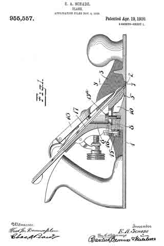
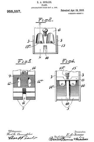
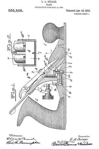
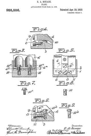
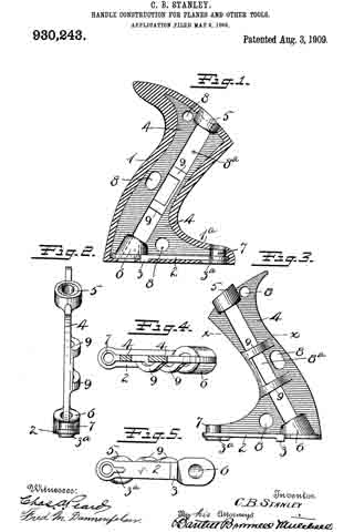
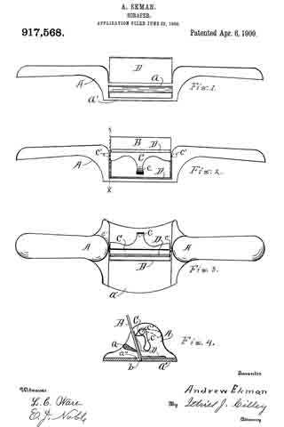
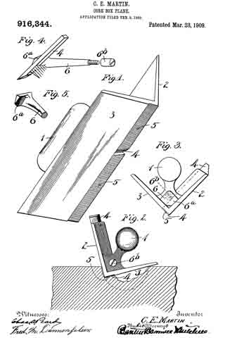
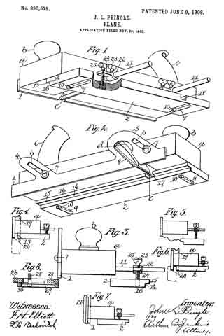
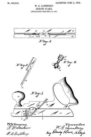
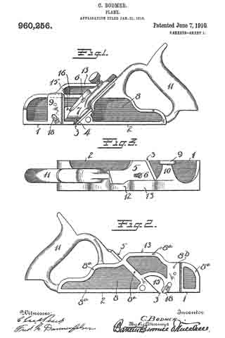
In the accompanying drawings, Figure 1 is a side elevation of the complete plane, looking up from the left hand side. Fig. 2 is a view of the reverse or right hand side of the plane body. Fig. 3 is a plan view of Fig. 2. Fig. 4 is a relatively enlarged view showing a part of the plane in longitudinal section. Fig. 5 is a cross section of the plane on the line x–x. Fig, 6 is a cross section of the plane on the line y–y.

The plane body is cast in iron or steel and comprises the forward sole section 1 and the rear sole section 2, separated by a throat 3, in which the cutting edge of the plane-iron 4 stands when the plane is set up and adjusted ready for use.

5 is a seat for the plane-iron.

The throat 3 extends transversely and obliquely entirely across the plane body as best seen in Fig. 1, and it follows therefore, that the seat 5 not only inclines rearwardly but slants down toward one side of the plane. Any suitable mechanism may be employed for holding the plane-iron to the seat, such as the headed screw-stud 6 and the cap 7. The two sections 1–2. of the sole are integrally connected by a side plate 8 formed in this instance at the right hand side of the body, a part of the side plate bridging the throat 3 and being constructed, as hereinafter described, to afford great strength and to prevent warping and twisting. The plate 8 is provided with a raised bearing portion which is machined smooth, as indicated by the laterally offset ribs 8a–8a. These bearings 8a are raised with reference to the plain unfinished side of the said side plate 8, the area of said bearing portion being suflicient to afford a sufficiently long and broad seat, at the same time being much less than the entire area, thus simplifying exceedingly the operation of machining.

9 is an upwardly projecting bearing support at the opposite side (the left hand side) of the plane body, the same being in this instance parallel with the bearing portion of the side plate 8, and at right angles to the plane of the sole sections 1–2. This bearing-section 9 is connected integrally not only with the sole section 1, but also with the opposite side plate 8, said last connections being effected through the medium of the bridge rib 10.

11 is a handle preferably cast integrally with the plane body, but of course may be made capable of being connected to said plane body in any well known or desirable manner.

Referring particularly to the views 4–6, the connections between the throat and the rib sections of the plane will now be described. It is to be understood that the plane-iron, in this type of plane, is widest at its lower end, its middle and upper portion being narrowed down to clear the side plate 8. In the present instance, I avail myself of this feature to specially construct the bridge connection between the two sole sections, providing, where necessary, a solid strong mass of material and wherever possible a ribbed construction to secure the necessary strength and lightness. Immediately adjacent to the plane seat 5, where the side plate 8 leaves the rear section, I provide a relatively heavy mass of stock, as indicated at 12, Fig. 6. Immediately forward of this point, the bridge is arched up as indicated at 13, said arch descending at a point slightly forward of the plane of the throat and meeting the transverse bridge 10 which extends across to the opposite side-bearing or support 9. The lower part of the solid mass of material 12 near the lower end of the seat 5 is extended forwardly to form a curved rib 14, which performs the double function of a strengthening rib for the plane body and a deflector for the shavings, there being a clearance space 15 entirely through the plane body above the throat 3. This rib 14 curves forwardly and across the plane and meets the sole section 1 and the inner side of the support 9, being integrally formed with both of said parts. The arched portion 13 is provided with a recess or cavity 13a and between this recess or cavity 13a and the base of the rib 14 is a horizontally disposed strengthening rib 16, extending back to the heavy mass of material 12, and serving, together with the upper flange of the bridge 13 and the rib 14, to provide a connection between the sections 1–2 of maximum strength and minimum of weight. The inside of the plane body is of course hollowed out as at 17–17 to lighten the structure.

18–18 are scoring spurs or cutters employed on opposite sides of the plane to form score lines in advance of the plane-iron 4, said score lines being coincident with the opposite edges of said plane-iron.

The part 9 performs, in addition to the function of bearing for the adjacent side of the plane, the function of a support for a depth gage, such as is customarily employed in planes of this character. The opposite side (right hand side) plate is provided with a supporting portion 8b, upon which a depth gage may be adjustably supported. Since gages and other plane attachments are well known, no particular description is required herewith, it being merely proper to state that the part 8b performs not only the function of a bearing, but also a support for any attachment such as is customarily employed in tools of this character.

As has already been stated, my invention aims at producing a plane body of the type referred to which shall be accurately formed. One of the great difficulties to overcome I will now describe. It is a well known fact that the machining of the outer flat face of a casting releases the surface tension and permits the tension on the opposite (unmachined) face to act in such a manner as to twist and warp the structure; to illustrate, were it not for the recessed form of the outer face of the side plate 8, the machining of that side to produce a bearing surface would release the surface tension on the outer side and result in warping and buckling, tending to distort and throw out of line the two sole sections 1–2 of the plane body. This buckling would occur during or immediately following the machining process. To avoid this disastrous effect, I provide a construction which requires the machining of such a relatively small area of the surface 8 that the surface tension is not released to any dangerous extent. Consequently, the tension being substantially balanced on the opposite surface of the side plate 8, all tendency to injurious warping or twisting is eliminated. It should be stated that the unmachined held of surface metal between the bearing faces 8a of the side plate 8 affords more than a mere panel intended only for the reception of a name or number. In the present instance, this unmachined surface of substantial area is so located as to overcome the aforesaid injurious tendency of warping by reason of the lessening of the surface tension at the vulnerable point.

A further advantage growing out of this construction is the rapidity and ease with which this machining process may be effected. The sum of these advantages results in great economies that add to the durability or accuracy of the instrument.

While of course I have shown herein the preferred embodiment of my invention, it is obvious that in some respects the construction may be modified or varied without changing materially those features of improvement which characterize my invention. Hence it may be stated that I contemplate that reasonable latitude may be had in the particular design resorted to.

What I claim is:

1. A plane body formed of cast metal including two sole sections separated by a throat, a wall or plate integrally connecting said sections by an arch at one side of the plane body and including a plurality of substantially horizontally disposed and inwardly directed spaced ribs extending laterally across the plane body, a standard at the opposite side of the plane forming a bearing support projecting upwardly from the forward sole section and connected to the last mentioned rib, and still another rib extending across the plane body from the support on one side to the plate on the other side and forming a combined deflector and strengthening rib.

2. A plane body formed of cast metal including two sole sections separated by a throat, a wall or plate integrally connecting said sections by an arch at one side of the plane body and including a plurality of substantially horizontally disposed and inwardly directed spaced ribs extending laterally across said body, a standard at the opposite side of the plane forming a bearing support projecting upwardly from the forward sole section and connected to the last mentioned rib, and still another rib extending across said body from the support on one side to the plate on the other side and forming a combined deflector and strengthening rib, said last mentioned rib being also integrally connected with said bearing support and one of said sole sections.

3. A plane body formed of cast metal including two sole sections separated by a throat, a wall or plate at one side, connecting said sections by an arch at one side of the plane body, a standard at the opposite side of the plane forming a bearing support, the inner side of said standard being integrally connected to the inner side of said wall or plate, the outer or bearing side of said plate where said arch is formed having a relatively raised bearing surface, said bearing surface being machined, the relatively unraised portion being unmachined to balance surface tension on opposite sides of said plate at said arch.

4. A plane body formed of cast metal including two sole sections separated by a throat, a wall or plate connecting said sections at one side of the plane body and including a plurality of substantially horizontally disposed ribs at the inner side of said side plate, the outer or bearing side of said side plate having a relatively raised bearing surface, said bearing surface being machined, said unraised portion being unmachined, said unmachined surfaces being so disposed relatively to the forward and rear sections of the sole portions of the plane as to retain surface tension at the point where buckling would tend to occur between the two sole sections.

5. A plane body comprising a forward sole section and a rear sole section arranged in line and separated by a narrow throat, a wall or plate connecting said two sections at one side of the plane body, all of said parts being formed integrally by casting, the outer bearing surface of said wall or plate including a smoothed machined bearing surface and an umnachined surface arranged in a plane slightly below the plane of the bearing surface, said unmachined portion being so located with relation to the forward and rear sole sections as to retain surface tension at the point between the front and rear sole sections where buckling would tend to occur.

CHRISTIAN BODMER.

Witnesses:
THOMAS K. O’CONNOR,
JOSEPH M. HANCE.

No. 955,557 – Plane (Edmund A. Schade) (1910)

[paiddownloads id=”670″]955557


UNITED STATES PATENT OFFICE.

_________________

EDMUND A. SCHADE, OF NEW BRITAIN, CONNECTICUT, ASSIGNOR TO STANLEY RULE &
LEVEL COMPANY, OF NEW BRITAIN, CONNECTICUT, A CORPORATION OF CONNECTICUT.

PLANE.

_________________

955,557. Specification of Letters Patent. Patented Apr. 19, 1910.
Application filed November 4, 1909. Serial No. 526,204.

_________________

To all whom it may concern:

Be it known that I, EDMUND A. SCHADE, a citizen of the United States, residing at New Britain, county of Hartford, State of Connecticut, have invented certain new and useful Improvements in Planes, of which the following is a full, clear, and exact description.

My invention relates to improvements in planes.

The object of the invention is to provide a simple and effective means to facilitate the adjustment of the plane frog to and fro for the proper positioning of the cutting edge of the plane iron in the throat of the plane.

In the drawings — Figure 1 is a longitudinal section of a plane taken approximately on the plane of the line x–x of Fig. 2, certain parts being shown in elevation; Fig. 2 is a cross section of the body of the plane on the line y–y, Fig. 1, showing a portion of the plane frog in elevation; F ig. 3 is a view of the under side of the forward part of the plane frog; Fig. 4 is a plan view of that part of the body of the plane which supports the frog.

1 represents the sole of the plane body; 2 the throat therein, and 3–3 are the cheek pieces. Immediately to the rear of the throat 2 is a smooth bearing support 5 designed to receive a cooperating bearing surface 7 at the forward end of the frog 6. Still farther to the rear of the throat 2 is an elevated bearing support 8, the rear portion of which is constructed to receive and support a cooperating bearing surface 9 on the frog. The bearing supports 5–8 are spaced apart so that the frog will be supported at two different points.

10 is a longitudinally arranged guide and strengthening rib on the upper side of the sole of the plane extending rearwardly from a point at or near the throat 2.

11 is a groove or slot in the under side of the frog, the side walls of which are arranged to take a bearing upon the side walls of the rib 10 whereby said rib 10 will serve to hold the frog in correct aiinement and guide the frog in its movement to and fro, thereby avoiding any twist or lateral displacement of the frog as it is being adjusted.

12–12a are longitudinal slots in the frog, parallel with the groove 11 but somewhat to the rear of the same. These slots are arranged to receive clamping screws 13–13a respectively. The lower ends of these clamping screws take into threaded openings 14–14a respectively in the sole of the plane which openings are arranged forward of the most elevated portion of the support 8.

15 is an adjusting screw carried by the sole of the plane at the rear of and below the bearing 8. This screw has a groove 15a arranged to receive a yoke 16, which is secured to the rear of the frog. When the screw 15 is moved to and fro, it will impart a corresponding movement to the frog.

17 is the plane iron or cutter held in place on the frog by the usual cap 18.

In operation, the frog is secured in place by means of the screws 13–13a, the same being set down snugly so as to prevent accidental or unintentional displacement of the frog. The strain of these screws, as shown, comes upon an intermediate part of the frog between the supports 5–8. The plane iron and cap are then applied. The adjustment of the plane iron for the purpose of projecting or retracting the cutting edge of the same may be accomplished in any well known manner, that being immaterial to my invention. If it is found that the position of the plane iron, fore and aft, in the throat 2 should be changed, it is merely necessary to move the screw 15 in the proper direction and to the desired extent, producing thereby the desired movement and adjustment of the frog. If by chance (and it is practically impossible to prevent it) one of the screws 13 or 13a is screwed down more tightly than the other, it is obvious that any movement to and fro of the frog would tend to twist the same upon its bearing supports by reason of an abnormal drag on one side of the center line. The provision of the guide rib 10 which fits between the guide walls of the groove 11 will prevent this displacement. I have found that even though the screws 13–13a be screwed down very tightly nevertheless adjustment of the frog by means of the screw 15 alone may be readily effected, due doubtless to the smooth bearing supports 5–8 and the co-acting smooth bearing surfaces 7–9 and to the fact that there is sufficient elasticity or spring in the frog along the line of the clamping screws 13–13a to prevent the absolute locking of the frog. While the clamping engagement of the screws 13–13a is not sufficient to prevent the intentional adjustment of the frog by the screw 15, said clamping engagement is quite sufficient to prevent accidental or unintentional displacement of the frog, particularly as in this respect the guiding rib 10 and the adjusting screw 15 cooperate with the clamping screws 13–13a in the retention of the frog in any of its adjusted positions.

l am aware that heretofore separated frog supports, adjusting screws, clamping screws and reinforcing ribs are old but in the present instance I have added a new function to the reinforcing rib, viz., the guiding function, and have thereby produced a means for permitting the quick and accurate adjustment of a plane frog, which means is vastly more simple and far more effective than any adjusting means heretofore produced in that it eliminates certain parts and operations heretofore regarded as essential, simplifies the act of adjusting, and guarantees a straight line movement of the frog to and fro. ln devices of this character it is desirable that the plane iron should be in position when the adjustment of the frog is being effected. By my improvement this is possible.

It is obvious that the number of guiding ribs 10 employed may be increased, but one is sufficient, and is, indeed, preferable. It is obvious that the rib 10 may engage the side walls of the groove 11 throughout their entire length, but in the preferred form it is desirable to cut back or narrow the top of the rib to the rear of its front end, so that the active guiding part of the rib is comparatively short and close to the throat. By this arrangement a slight lateral adjustment of the extreme rear end of the frog may be had in assembling the plane, only a very slight adjustment at this point ever being required (if at all) to secure the accurate positioning of the frog on the supports 5 and 8 relatively to the throat.

In practice I accomplish the proper positioning of the frog on its support in the following manner: Before tightening up the screw which holds the fork in its place, I place the forward end of the frog in its proper position upon the rib and then swing the rear end of the frog to right or to left as may be necessary to secure perfect alinement between the frog and center line of the plane bottom. During this swinging movement the fork 16 (loose on its own fastening screw) engages the circular groove 15a. When perfect alinement is secured, I force home the screw which holds the fork, thereby securing all the parts in cooperative combination. In this way the fore and aft movement of the frog on the plane bottom is made to be in perfect alinement throughout. When the fore and aft movement is secured in this manner the front edge of the frog is always parallel to the throat of the plane. This method is found to be advantageous in practice, although it is evident that with sufficient pains the proper cooperative relations of the frog and plane bottom may be secured even if the fork were firmly fastened in the first instance.

It is evident that yoke 16 and the adjusting screw 15 may be reversed, that is to say, the yoke may be secured by a screw to the bottom of the plane and the adjusting screw be inserted in the rear of the frog, these two elements cooperating with each other in the same way, whichever one of them may be uppermost. Likewise the fork may be cast integral with the portion of which it is a part.

What I claim is:

1. A bench plane comprising a body portion having a transverse throat in the sole portion thereof, a frog support to the rear of said throat, a frog mounted thereon for adjustment to and fro, means for frictionally clamping said frog to said support, a combined guide and operating means located at and accessible at the rear of the frog for moving said frog on said support longitudinally of the plane body, and a guiding rib and groove engagement between said frog and support adjacent to the throat of the plane whereby said frog will be prevented from twisting out of correct alinement relatively to the throat as it is adjusted to and fro.

2. A bench plane comprising a plane body having a transverse throat in its sole portion, a frog support, a frog mounted thereon, means for frictionally clamping said frog to said support on both sides of the central vertical plane thereof, and intermediate its forward and rear ends a single positively operating means for adjusting said frog on said support longitudinally of said plane, and a guiding rib and groove engagement between said frog and support at the forward end of the frog and adjacent to the throat of the plane whereby the said single adjusting means will move the frog parallel with said central vertical plane regardless of difference of degree of clamping between said clamping means.

EDMUND A. SCHADE.

Witnesses:
W. J. WORAM,
I. W. CHAPMAN.

No. 955,556 – Plane (Edmund A. Schade) (1910)

[paiddownloads id=”669″]955556


UNITED STATES PATENT OFFICE.

_________________

EDMUND A. SCHADE, OF NEW BRITAIN, CONNECTICUT, ASSIGNOR TO THE STANLEY RULE
& LEVEL COMPANY, OF NEW BRITAIN, CONNECTICUT, A CORPORATION OF CONNECTICUT.

PLANE.

_________________

955,556. Specification of Letters Patent. Patented Apr. 19, 1910.
Application filed March 18, 1909. Serial No. 484,099.

_________________

To all whom it may concern:

Be it known that I, EDMUND A. SCHADE, a citizen of the United States, residing at New Britain, county of Hartford, State of Connecticut, have invented certain new and useful Improvements in Planes, of which the following is a full, clear, and exact description.

My invention relates to improvements in planes, the main object being to provide superior adjusting means.

In the accompanying drawings, Figure 1 is a longitudinal section of the body of a plane and certain parts, showing also certain other parts in side elevation, this section being taken on approximately the line W–W Fig. 2. Fig. 2 is a cross-section on the line X–X Fig. 1, looking in the direction of the arrow. Fig. 3 is a cross-section on the line Y–Y Fig. 1, looking in the direction of the arrow. Fig. 11 is a cross-section on the line Z–Z Fig. 1, looking in the direction of the arrow. Fig. 5 is a central longitudinal section of certain parts of the plane. Fig. 6 is a longitudinal section taken on the same plane as the section of Fig. 1 and showing a modiication. Figs. 7 and 8 are side elevations of companion parts. Fig. 9 is a side elevation of a modified part.

1 represents the frame of a plane provided with the usual sole and cheek pieces, and having the usual handles 2–2.

3 is a saddle mounted on the sele of the plane and preferably integral therewith. This saddle 3 furnishes a support for the frog 4, upon which is mounted the plane-iron 5, the same being secured thereto by the well known clamp 5a not necessary to describe in detail herein. The forward or cutting edge of the plane-iron 5 projects through a throat 6 in the sole of the plane. In the particular form shown, the saddle 3 is provided with a rib 7, which enters a groove in the lower end of the frog 4 and so fits the same that it operates as a guide to guarantee an accurate fore and aft movement of the frog relatively to the longitudinal axis of the plane while adjustment is being effected. The frog is suitably shaped to rest upon the saddle 3 so that it may be adjusted back and forth, thereby shifting as desired the cutting edge of the plane-iron 5 forward and back in the throat 6. The usual adjusting mechanism to vary the projection of the plane-iron may be provided, but, since the same constitutes no part of this invention, it need not be described herein.

The particular feature of invention herein disclosed relates to the adjustment of the frog, whereby the throat clearance may be varied. To accomplish the adjustment of the frog, I provide an adjusting screw 8 mounted at the rear of the saddle 3 and operating to and fro. A forked plate 9 carried by and at the rear of the frog 4 stands in an annular groove in the head of the screw 8 so that as the screw 8 is operated to and fro, it imparts a corresponding movement to the frog, provided the latter is not locked in place. To lock the latter in place, I provide a simple and effective clamping mechanism comprising (in the form shown in Figs. 1 to 4 and 6 and 7) the tubular shank 10 arranged vertically in a suitable bore in the saddle 3. As shown, two of these tubular shanks 10 are provided and each of these shanks is preferably threaded to receive a screw 10a, the shank of each screw standing in a longitudinal slot 4a in the frog 4.

11–11 are set-screws which pass into the rear of the saddle 3 so as to be easily accessible from the rear. These screws preferably have conical noses at the forward end, which pass into recesses in the side of each sleeve 10 so that when said screws 11 are advanced they will operate to force the sleeves 10 down so as to clamp the heads of the screws 10a tightly against the frog, in turn drawing the frog hard down against the saddle 3. Ordinarily, in planes of this character, it has been necessary, in order to adjust the frog, to remove the plane-iron 5. Inasmuch as the degree of throat clearance cannot be accurately and quickly determined when the plane-iron is removed, it follows that an adjusting device which is accessible and operable when the plane-iron is in place, furnishes an exceedingly valuable improvement.

By my invention all that is required is to simply loosen the screws 11–11, after which the adjusting screw 8 may be turned in a direction to advance or retract the frog to the desired extent. When the proper adjustment has been attained, the set-screws 11–11 are advanced by a screw-driver entered from the rear, until the heads of the screws 10a draw down on the frog and clamp it firmly to the saddle.

During the period of adjustment, the rib serves to guide the forward edge of the frog to and fro in exactly the proper line, thus relieving all the other parts of this burden. While of course an approximate alinement might be given by the cheek-pieces, it would require an expensive machining operation to so finish the cheek pieces and frog sides that accurate alinement, from this source, could be relied upon. By my invention the rib 7 may be cast integrally with the saddle and the groove in the lower side of the frog which rides on the rib may be quickly and easily formed so as to guarantee the maximum of perfection in adjustment at a minimum of expense and labor.

In the modification shown in Figs. 6 and 9, I provide the solid clamping stud 10b in place of the companion parts 10–10a, and in this case, instead of providing a tubular sleeve similar to 10, I provide a solid shank for the stud 10b.

I am aware that various modifications may be made, and, so long as the construction selected provides for adjustment of the frog without removing the plane-iron therefrom, I deem such modification as within the scope of the broadest of the claims herein.

What I claim is:

1. In a plane, a body portion having a sole and a throat therein, a frog support arranged at the rear of said throat and extending transversely across the sole, a frog mounted on said support, and adjustable to and fro, means for adjusting said frog comprising a screw accessible at the rear of said frog, means to secure said frog on said support comprising a clamping device projecting downwardly through the frog and into said support, a locking device comprising a screw entering said support from the rear, the forward end of said screw having a cone head, a recess in said clamping device into which said cone head may be projected, the inclined wall of said cone head engaging and forcing said clamping device in a direction to rigidly secure said frog in place.

2. In a plane, a body portion having a sole and a throat therein, a frog support arranged at the rear of said throat and extending transversely across the sole, a frog mounted on said support and adjustable to and fro, means for adjusting said frog comprising a screw accessible at the rear of said frog, means to secure said frog on said support comprising a two part clamping device projecting downwardly through the frog and into said support, a locking device comprising a screw entering said support from the rear, the forward end of said screw having a cone head, a recess in said clamping device into which said cone head may be projected, the inclined wall of said cone head engaging and forcing said clamping device in a direction to rigidly secure said frog in place, said clamping device being adjustable as to length.

EDMUND A. SCHADE.

Witnesses:
W. J. WORAM,
I. W. CHAPMAN.

No. 949,691 – Plane-Guide (William T. Whiteway) (1910)

[paiddownloads id=”668″]949691


UNITED STATES PATENT OFFICE.

_________________

WILLIAM T. WHITEWAY, OF CAMBRIDGE, MASSACHUSETTS.

PLANE-GUIDE.

_________________

949,691. Specification of Letters Patent. Patented Feb. 15, 1910.
Application filed December 17, 1907. Serial No. 406,911.

_________________

To all whom it may concern:

Be it known that I, WILLIAM T. WHITEWAY, a citizen of the United States of America, residing at Cambridge, in the county of Suffolk and State of Massachusetts, have invented new and useful Improvements in Plane-Guides, of which the following is a specification.

This invention relates to plane-guides, and one of the principal objects of the same is to provide detachable and adjustable guides for planes which can be quickly adjusted and which will serve to hold the plane in alinement with the edge of a board.

Another object is to provide a plane-guide which can be used as a try-square, side gage, or supplemental sole.

These and other objects may be attained by means of the construction illustrated in the accompanying drawing, in which :–

Figure 1 is a perspective view of a metal jack-plane of ordinary construction having two guides secured to one side thereof. Fig. 2 is a longitudinal section through one of the guides and the guideway and keeper for said guide.

Referring to the drawing for a more specific description of my invention, the numeral 1 designates a plane which may be of any suitable construction and preferably provided with a side member 2 having a dovetailed upright groove 3 formed therein near each of its front and rear ends and by preference forward and backward of the cutting blade which latter at its edge may stand as close to the side 2 as desired. The grooves are open at top and bottom and laterally through the side 2, and hence when the guides are not employed the grooves cannot readily become clogged with sawdust, or if it accumulates therein it can easily be shaken out. Into these grooves are fitted guides 4, preferably counterparts of each other so that they are interchangeable, and each guide consists of a straight bar of a size to closely yet adjustably fill the groove, having a flat outer face which will stand flush with the side 2 of the plane and a flat inner face which will stand at right angles to the sole 9 of the plane, and rounded ends 5. In length the bar is preferably such that when in place it will project both above and below the plane body as shown; and it may be adjusted in its groove so that its lower end will stand above the sole when its presence will not interfere with the ordinary use of the plane, or so that its lower end will project below the sole more or less when it may be employed as a guide to hold the plane on the edge of a board or on its side adjacent its edge. Obviously one or both guides may be withdrawn entirely; or, when one is used and the other raised or withdrawn, one end of the plane will be guided along the board and the other may be deflected from the line of travel so as to produce a shearing action of the cutting blade which then stands slightly oblique. Finally, either or both of the guides 4 when projected below the sole 9 stand at right angles thereto and may be used for squaring work as will be understood; and a plane having one or more of these guides will not dull its blade if thrown upon the bench, because the lower end of the guide holds the sole elevated.

In connection with the guides, I prefer to employ keepers as shown. These consist each of a straight bar much like the bar of each guide except that it is preferably rectangular in cross section, and the two keepers 6 are also counterparts of each other. Each stands across one groove at about the center of its vertical length and is secured flat to the side face 2 of the plane parallel with the sole 9. The keepers are in alinement with each other longitudinally, and hence their flat outer faces will constitute a side gage to hold the plane at a uniform distance from an upright along which planing is to be done, and their flat lower edges will constitute a supplemental sole to limit the depth to which the cutting of the plane may proceed. These keepers stand only across the midlength of the upright grooves, and hence sawdust in the latter may be easily dislodged as by tapping the plane against the bench.

By preference the keepers are attached to the plane by screws 7 having countersunk heads as shown so that the flat outer face of the keepers is not interrupted. Such means of attachment renders the keepers removable when desired, yet without detracting from their function just set forth. By preference also a set screw 8 is passed inward through a threaded hole at about the center of each keeper and its inner end bears flat against the outer face of the guide beneath, whereby the latter is positively held against movement in its groove and is still capable of adjustment by first loosening the set screw. The threaded hole through the keeper is open at both ends when the screw 8 is removed, and sawdust can be easily dislodged therefrom; and the use of the set screws is therefore useful though not absolutely necessary. In the complete device, I prefer to employ all these attachments and sell them with the plane as illustrated; but with proper use they provide the plane with a guide, a side gage, a supplemental sole, and a square, and it is even possible to use the plane with a shear cut as above set forth.

Having thus described the invention, what is claimed as new, is :–

1. A plane provided in one side near its front and rear ends with upright dovetailed grooves open at top and bottom and laterally through said side; combined with two guides, each consisting of a straight bar of a section to fit either groove closely but adjustably and having a flat outer face standing flush with the side of the plane and a flat inner face standing at right angles to its sole.

2. A plane provided in one side near its front and rear ends with upright dovetailed grooves open at to and bottom and laterally through said side; combined with two guides each consisting of a straight bar of a I section to fill either groove and having a flat outer face flush with the side of the plane, two keepers each secured across a groove with their lower edges parallel with each other and the sole of the plane, and a set screw through each keeper against its guide.

3. A plane provided in one side near its front and rear ends with upright grooves open at top and bottom and laterally through said side; combined with guides each consisting of a straight bar standing in and longer than said groove and having rounded ends and flat inner and outer faces, keepers standing in alinement with each other and extending across said grooves between the ends of the latter, said keepers having their lower edges parallel with the sole of the plane and their outer faces parallel with its side, screws removably securing the keepers to the plane and having countersunk heads, and a set screw through the keepers against each guide.

In testimony whereof I affix my signature in presence of two witnesses.

WILLIAM T. WHITEWAY. [L. S.]

Witnesses:
WALTER E. ROGERS,
SARAH WHITEWAY.

No. 936,085 – Woodworker’s Plane (James Horace Brown) (1909)

[paiddownloads id=”665″]936085


UNITED STATES PATENT OFFICE.

_________________

JAMES HORACE BROWN, OF BOSTON, MASSACHUSETTS.

WOODWORKER’S PLANE.

_________________

936,085. Specification of Letters Patent. Patented Oct. 5, 1909.
Application filed November 17, 1908. Serial No. 462,996.

_________________

To all whom it may concern:

Be it known that I, JAMES HORACE BROWN, a citizen of the United States, and a resident of Mattapan, Boston, in the county of Suffolk and State of Massachusetts, have invented a new and Improved Woodworker’s Plane, of which the following is a full, clear, and exact description.

The purpose of this invention is to provide novel details of construction for a plane, that facilitates the exact adjustment of the cutter bit laterally and longitudinally in the throat of the plane stock, enable the quick and exact graduation for size of the throat opening in said stock, provide novel means for clamping the cutter bit when adjusted in the throat opening.

The invention consists in the novel construction and combination of parts, as is hereinafter described and defined in the subjoined claims.

Reference is to be had to the accompanying drawings forming a part of this specification, in which similar characters of reference indicate corresponding parts in all the views.

Figure 1 is a partly sectional side view of the improved plane, substantially on the line 1–1 in Fig. 2; Fig. 2 is a partly sectional plan view, substantially on the line 2–2 in Fig. 1; Fig. 3 is a fragmentary plan view, partly in section on the line 3–3 in Fig. 1; Fig. 11 is a sectional side view of details shown in Fig. 1, but showing a changed adjustment thereof and Fig. 5 is a partly sectional view of parts, taken substantially on the line 5–5 in Fig. 1.

The stock for the plane is cast into form from metal, and essentially consists of a flat base plate 10 having vertical walls 10a formed along its side edges, and said side walls having their greater height near their longitudinal centers are curved on their upper edges, as shown for one side wall in Figs. 1 and 4. At a suitable distance from the front end of the stock 10, a transverse throat opening a is formed in the base portion thereof, and at the front and rear edges of said throat, oppositely inclined defining walls a1, a2 are formed on said base portion, as is clearly shown in Fig. 1. Rearward of the throat opening a and parallel therewith, a post 11 is erected on the base 10, said post extending from one side wall 10a to the opposite one, as shown in Figs. 1 and 3, and being located near the longitudinal center of the plane stock.

Novel means is employed for graduating the width of the slot opening a, consisting in the provision of a wedge-shaped tongue piece 12, seated upon the inclined rear defining wall a2 of the slot a, said tongue piece extending across the stock into loose engagement with the inner surfaces of the side walls 10a. The tongue piece 12 is provided with a rearward extension 12a in the form of a flat plate, having at its end a fork 12 projecting from its lower face and adjacent to said fork a cross slot b. The post 11 is thickened near its junction with the base 10, and in said thickened portion a threaded perforation is formed, in which the threaded body of an adjusting said screw screw 13 is screwed, said screw having a roughened head 13a formed or secured on the rear end thereof. The screw 13 extends between the members of the fork 12b and is provided at its end with a collar 13b which projects into the slot b, so that by manipulating the screw the tongue piece 12 can be adjusted to increase or decrease the width of the slot a. The connection between the tongue and screw, permits the tongue to be readily detached from the screw and removed when desired.

The cutter bit 14 of the plane, is in the form of a flat metal plate, preferably formed of steel and having one end beveled to produce a transverse cutting edge c thereon. At the transverse center, a longitudinal slot d is formed in the cutter bit 14 extending of a suitable length between the ends thereof. The cutter bit 14 is seated upon the tongue piece 12 and the upper end of the post 11, said end being sloped forward and downward, as shown in Fig. 1, to adapt it for a proper support of the bit. The bit 14 is held seated upon the tongue piece 12 and post 11 by a novel clamping device that also serves the purpose of a cap plate for the cutter bit, said device comprising the following details: A resilient thin metal plate 15 having a proper length, and a width that is equal with that of the cutter bit, is secured by one end that is uppermost in service upon a spacing block 16 whereon a resilient hook plate 17 is also secured. The spacing block 16 is a flat rectangularly-edged slab of metal from the rear end of which projects a flange 16a at a right angle, said block having parallel sides. The hook is of an equal width with the resilient cap plate 15, and these plates at their upper ends are oppositely lapped upon the upper and lower surfaces of the spacing block 16, whereon they are secured by a rivet or screw, as shown at e. Upon the lower or forward end of the plate 17, a transverse hook g is formed, that is adapted for a hooked engagement with a keeper bar 18 that extends across the stock of the plane above and in contact with the cap plate 15, and is secured by its ends in the side walls 10a of said stock. It will be seen that the hooked engagement of the plate 17 with the keeper bar 18, will hold the cap plate 15 imposed upon the cutter bit 14; and to enforce said engagement set screws h are inserted in the cap plate and spacing block 16, that will graduate the pressure of the cap plate in accord with the degree of projection given the set screws, that bear on said cutter bit near each side edge thereof, as shown in Figs 1, 2 and 4.

In the post 11, near its upper edge, a screw 19 is secured by one end thereof, and thence extends rearward and upward. Upon the threaded body of the screw 19, a sleeve nut i1 is loosely mounted, said nut having a radial flange i formed thereon, and upon a portion of the cylindrical body of said nut, a thread is cut. Upon the threaded body of the nut i1, a nut i2 having a body similar to the flange i is adjustably mounted and adapted for rotatable movement toward or from the flange i. Near the upper end of the cutter bit 14, a transverse slot d1 is formed that crosses the longitudinal slot d. Below the slot d, the adjusting screw 19 is positioned and in such close relation to the cutter bit 14 that the radial flange i1 and the nut i2 will project into the transverse slot a1 and by lateral adjustment may be caused to have lateral contact with the side edges of said slot.

It will be seen that by a screwed adjustment of the nuts i, i2, on the body of the adjusting screw 19, there may be an exact longitudinal adjustment given to the cutter bit let for its projection or retraction in the transverse throat slot a; further, by screwing the flange i1 and nut i2 into an engagement with the defining sides of the cross slot d1, the cutter bit 14 will be firmly held at a desired point of longitudinal adjustment thereof.

Upon the adjusting screw 19, near the post 11, a lever 20 is mounted and secured near one end thereof, a toe m extending from the upper end of said lever through the slot d, having a loose engagement with the defining side edges thereof, the main portion of said lever projecting down near to the base 10, and it will be noted that a side movement of the lever will slightly rock the cutter bit 14 accordingly and thus depress a respective corner of the cutting edge of the bit, enabling an exact adjustment of said edge to adapt it to have a true bearing on the material over which the plane is moved in planing it.

At the front end, a knob 21 is secured that projects vertically from the plane stock, this being a common provision to enable hand pressure to be applied upon the front end of the plane.

The handle 22 of the plane, is provided with a forwardly-projecting flange n at the lower end thereof, said flange having a notch o in the front edge, which receives a stud o1 formed on the rear portion of the base of the stock at its transverse center. The body of the handle 22, is preferably given skeleton form, that affords a flat bottom wall n1 thereon, which is centrally perforated and registers with a threaded perforation formed at the transverse center of the base portion 10; and it will be seen that if the stud o1 is placed in the notch o and a screw p is inserted through the perforation in the handle down into the threaded perforation in the base 10, the handle 22 will be firmly but detachably secured upon the plane stock.

It will be apparent from the foregoing description, that the cutter bit 14 may be given different degrees of inclination on the stock by an adjustment of the tongue piece 12 toward or from the throat slot a; the cap plate 15 may be adjusted for graduating its pressure on the cutter bit and is not connected therewith other than by frictional contact. The provision of the adjusting screw 19 and flanged nuts i and i2 thereon that are adjustable in the cross slot d1, greatly facilitates the exact adjustment of the bit 14 so as to cut a thick or thin shaving from the material operated upon, and this in conjunction with the lever 20 enables a close accurate adjustment to be given to the edge of the cutter bit.

Having thus described my invention, I claim as new and desire to secure by Letters Patent:

1. In a plane, the combination with a stock having a base portion and side walls thereon, said base having a transverse throat opening therein, a post erected on the base a distance rearward from the throat opening, and a cutter bit seated upon the tongue piece and upon the post, of a clamping device comprising a resilient cap plate, a hook plate, a spacing block whereon the end portions of the cap plate and hook plate are secured, a hook formed transversely on the free end of the hook plate, a keeper bar secured at its ends in the side walls of the stock and whereon the hook plate is hooked, and means for enforcing spring pressure of the clamping device upon the cutter bit.

2. In a plane of the character described, the clamping device for the cutter bit, comprising the resilient cap plate, the hook plate having a hook on one end thereof, the spacing block secured between the adjacent ends of the cap plate and hook plate, and adjusting screws carried by the spacing block.

3. In a plane, the combination with a stock having a transverse member, and a cutter bit, of a resilient cap plate engaging the bit, a member carried by the cap plate and engaging the transverse member of the stock, and means for increasing the pressure of the cap plate upon the bit.

4. In a plane, the combination with a stock having a transverse member above the base thereof, and a cutter bit, of a resilient cap plate engaging the bit, a member secured at its upper end to the cap plate and having a hook at its lower end engaging the transverse ineniber of the stock, and screws arranged between the cap plate and bit for increasing the pressure of said cap plate.

5. In a plane, the combination with a stock having side walls and provided with a bar extending between the side walls of the stock, and a cutter bit, of an angular block, two resilient plates secured upon opposite sides of one member of the said block, one plate resting upon the cutter bit and the other provided with a hook at its free end engaging the said bar, and screws projecting from the inner face of the said block and engaging the cutter bit.

In testimony whereof I have signed my name to this specification in the presence of two subscribing witnesses.

JAMES HORACE BROWN.

Witnesses:
MICHAEL F. HART,
F. HOWARD HALLETT.

No. 946,178 – Combination Woodworking-Plane (Mardonious L. Carter) (1909)

[paiddownloads id=”667″]946178


UNITED STATES PATENT OFFICE.

_________________

MARDONIOUS L. CARTER, OF GLASSPORT, PENNSYLVANIA.

COMBINATION WOODWORKING-PLANE.

_________________

946,178. Specification of Letters Patent. Patented Dec. 14, 1909.
Application filed February 13, 1909. Serial No. 477,535.

_________________

To all whom it may concern:

Be it known that I, MARDONIOUS L. CARTER, a citizen of the United States, residing at Glassport, in the county of Allegheny and State of Pennsylvania, have invented certain new and useful Improvements in Combination Woodworking-Planes; and I do declare the following to be a full, clear, and exact description of the invention, such as will enable others skilled in the art to which it appertains to make and use the same, reference being had to the accompanying drawings, and to the letters and figures of reference marked thereon, which form a part of this specification.

This invention relates to an improved combination wood-working plane for carpenters’ use, and it comprises a plane proper carrying the bits which in itself forms what is known in the art as a “smoothing plane” a detachable rear extension and means for securing the same which when in position converts said smoothing plane into a “jack plane” or one of greater length and by a further addition of a forward extension in addition to that of the rear the plane answers the purpose of a “fore plane”, and the invention further consists in the certain details of construction of parts as will be fully described hereinafter.

In the accompanying drawings:– Figure 1, is a central side sectional elevation of my improved combination plane showing the same converted into a fore-plane, the same being constructed and arranged in accordance with my invention. Fig. 2 is a similar view partly in elevation, showing the implement converted into at smoothing plane, the rear and forward extensions being adjusted and secured above the level of the base of same. Fig. 3 is a plan view of the converted fore plane, as shown at Fig. 1. Fig. 4; is an end elevation of the same. Fig. 5 is a cross section, taken on the line x x of Fig. 1.

To put my invention into practice and thereby construct a convertible hand plane for carpenters’ and joiners’ use and provide a combination of these planes in one, I form from cast metal a middle section which comprises a flat base 1, upwardly projecting sides 3, extending the entire length of said base, a cross portion 4 located above the throat 5 and an inclined integral rest 6 upon which the bits 7 are held by means of a plate 3 and screw 9 and rigidly secured by a thumb screw 10 operating in connection with a pivoted dog 11.

The above described construction differs but slightly from an ordinary smoothing plane such as are now in common use.

The base 1 of the middle section is rabbeted or reduced to one-half its thickness both at its forward and rear ends 2, and two threaded openings 17′–29′ formed through the base, and suitably located openings in the two side flanges 3 for the reception thumb screws 20 and 32 for the purpose securing the front and rear extensions, as will be fully described hereinafter.

The rear extension of the plane consists of a flat base 27 having side flanges 31, a rabbeted or reduced forward end 28 to register with and engage with the reduced rear end of the plane proper. Formed with this base 27 are parallel arranged dovetailed slides 36, which extend in the direction of its length and are adapted to contain a sliding dovetailed strip 35, in such manner that said strip may move freely therein. This strip 35 is secured rigidly in a certain position by means of thumb screws 29–30, engaging with the threaded opening 29′ in the base 1 of the plane proper and with a similar opening 30′ formed in the base of the extension, as will be best seen by reference to Fig. 1 of the drawings. This rearward extension is further secured and made more rigid with the plane proper by means of thumb screws 32 passing through the side flanges 3 and engaging with threaded openings formed in the flanges 31 of said extension (see Figs. 3 and 5) this making a permanent and rigid connection between the parts. The movable dovetailed member 35 carries an ordinary handle 33, such as are used on all wood planes said handle being attached by a screw 34 at the forward end and by another passing down through the same.

At the rear end of the base 27 of the rear extension is a threaded opening 30, and like openings 35′ are formed in the side flanges of the same, by means of which together with the thumb screws 32, this said extension may be adjusted to the position shown at Fig. 2 of the drawings, having first released the screws 29–30, moved the sliding member 35 back until the thumb screw 29 may engage with the forward threaded opening of the base 27 at which time the side screws 32 are adjusted to make a rigid connection of the parts. This backward movement of the sliding member 35 will bring the handle 33 and adjust the other parts to form the smoothing plane, the whole having been moved forward and on the top of the base 1 of the plane proper, and when in this position the forward extremity of the guides 36 will project beneath an offset 26 formed beneath the inclined bit rest 6′ and prevent any lateral or vertical movement of the extension.

The forward end of the plane proper is also fitted with an adjustable extension, the same consisting of a base 12, rabbeted to register with the front rabbet of the base 1, side flanges 14, parallel dovetailed guides 24 in which a corresponding movable member 23 operates in the direction of its length. This forward extension is secured in line with the plane proper by means of two thumb screws 17 and 18, together with side screws 20 in the same manner as that of the previously described rear extension. The sliding member 23 carries a knob or hand hold 16, common to planes of this class and when the said extension is in position to form a fore plane (as at Fig. 1) said sliding member is projected into a slot 25 formed at the base of the partition 41, and the extension held rigid with the plane proper by thumb screws 17 and 18, engaging the base of said extension and with the base of the plane proper. In addition to these two securing screws 17–18, side screws 20 are used which pass through the fianges of the two members, as will be seen by reference to Figs. 1 and 4.

To adjust the forward extension when the implement is to be used as a smoothing or jack plane the two screws 17–18 are released, the sliding member 23 moved back and the one screw 18 engaged with the threaded opening 19 and the extension more to a position on the top of the base 1 of the plane proper, the rear end of the sliding member 23 entering a pocket 22 formed in the partition at and the rear end of the base resting upon strips 25′ (see Fig. 2). The extension is now secured in this position by the side clamping screws 20.

By placing the front and rear extensions in position as at Fig. 1, a fore plane is formed, the handle 33 being first adjusted to the proper position.

To form a jack plane it is only necessary to adjust the forward extension to the position shown at Fig. 2, leaving the rear extension adjusted as shown at Fig. 1, and in order to convert the implement into a smoothing plane the front and rear extensions occupy a position as shown at Fig. 2.

The advantages of a convertible plane construction, as described are many, as is obvious among which are cheapness, as it takes the place of the three ordinary smoothing planes required for all ordinary carpenters’
practice, and it may be adjusted to occupy the minimum of space in a carpenter’s tool chest.

Various slight modifications and changes may be made in the details of construction without departing from the spirit of the invention. Therefore, I do not wish to confine myself to the construction, shown and described, but wish to claim all such modified forms as would come properly within the general scope of the invention.

Having thus described my invention, what I claim and desire to secure by Letters Patent, is:–

1. A bench plane, comprising a. plane proper, an extension therefor, means for attaching the extension with its sole in line with the plane sole, or with the sole in contact with the inner sides of the main sole plate, and a handle adjustable along the extension.

2. A bench plane, comprising a plane proper, a rearward extension therefor, means for attaching the extension with its sole in line with the plane sole, or with its sole in contact with the inner side of the main sole plate, and a handle adjustable along the extension, in combination with a forward extension, an adjustable knob carried by said extension, and means for locking said adjustable knob and extension to the plane proper.

In testiniony whereof, I affix my signature, in presence of two witnesses.

MARDONIOUS L. CARTER.

Witnesses:
W. G. WALTER,
ARTHUR V. McKEE.

No. 940,324 – Oil-Cup For Planes (David James) (1909)

[paiddownloads id=”666″]940324


UNITED STATES PATENT OFFICE.

_________________

DAVID JAMES, OF COFFEYVILLE, KANSAS.

OIL-CUP FOR PLANES.

_________________

940,324. Specification of Letters Patent. Patented Nov. 16, 1909.
Application filed June 22, 1907. Serial No. 580,239.

_________________

To all whom it may concern:

Be it known that I, DAVID JAMES, citizen of the United States, residing at Coffeyville, in the county of Montgomery and State of Kansas, have invented new and useful Improvements in Oil-Cups for Planes, of which the following is a specification.

My invention relates to improvements in oilers for planes.

The object of my invention is to provide a device of the character described, in which the lower face of the plane can be supplied with the proper amount of oil, and by which the oil supply opening can not be filled with dirt and prevent the proper operation of the oiler. Neither will the oil run from the oil cup when the plane is inverted.

Another object of my invention is to provide a more simple, cheap and effective oiler of this character to accomplish the result desired.

ln the accompanying drawings: Figure 1 is a longitudinal vertical sectional view of a plane, showing my improved oiler applied thereto; Fig. 2 is a top plan view of the plane partly broken away; and Fig. 3 is an enlarged detached view of the valve showing the several parts removed or separated from each other.

Referring now to the drawings, 1 represents a plane which is of the ordinary structure and having the usual boss 2 adjacent its forward end to which is attached an ordinary knob 3 for operating the same. In my improved oiler, this knob forms the oil cup, and, as shown, is of a spherical shape and hollow so as to receive and hold the oil. As shown, the boss 2 is externally screw-threaded and the oil cup provided with an internally screw-threaded opening 4, which is screwed upon the boss. The said boss is provided with a central opening 5 which extends through the lower face of the plane 6 and through which the oil passes to the lower face of the plane. The oil cap has an inwardly extending flange 7 which extends over the upper end of the boss and is provided with an opening 8 corresponding with the opening 5 in the boss. The said opening, at its upper end, is provided with an annular flange 9, the lower face of which forms the seat for the valve, as will be hereinafter more fully described.

The upper end of the oil cup is provided with an enlarged opening 10 through which the oil is placed in the cup and in which the operating button is placed. Within the oil cup is a vertically disposed valve stem 11 which extends downwardly through the opening within the flange 9 and below the same has rigidly secured thereto a valve 12, which, as shown, is of a circular form and fits firmly against the lower face of the flange 9 and forms a tight joint to prevent the escape of oil from the cup. The stem 11, adjacent its upper end, is screw-threaded and screwed thereon is a nut 13. Coiled upon the stem, below the nut, is a coil-spring 14 which has its lower end bearing upon the flange 9 and normally forces the valve stem upwardly and holds the valve firmly to its seat.

Screwed upon the extreme upper screw-threaded end of the valve stem is a head 15 which is of a size approximating that of the opening 10 and is provided with a reduced externally threaded sleeve 16 extending within the oil cup. Carried by this sleeve is a washer 17, preferably of leather, which engages the walls of the opening 10 and prevents the oil from leaking therefrom. Below the washer and carried by the sleeve is a nut 18 which is adapted to expand the washer and insure a perfect fit with the walls of the openings.

In order to prevent the screw-head from turning and accidental displacement from the valve stem, I provide the upper face of the oil cup, adjacent the opening 10, with an annular recess 19, having a screw-threaded opening into which is screwed a flat-headed screw 20, and the screw-head 15 is provided with a recess 21 into which the flat-headed screw 20 extends and prevents the head from turning. The head of the screw has a curved cut-away portion 22 which, when turned in its proper position, allows the head to be turned.

The valve stem 11 has its lower end screw-threaded at 23 and screwed thereon is a sleeve nut 24, the head portion of which fills the opening 5 in the boss and prevents the dirt, etc., from filling this opening 5. By turning this nut, it will be seen that the same can be adjusted so that it will hit a slight distance above the lower face 6 of the plane.

By pushing upon the screw-head, it will be seen that the valve stem is forced downwardly against the tension of the spring and the valve is unseated. The sleeve nut is likewise carried downwardly clearing the opening 5 of all the dirt and allows the oil to freely flow downwardly to the lower face of the plane. When the screw-head is released, it resumes its normal position and should the plane be inverted no oil will leak therefrom.

Having thus fully described my invention, what I claim as new and desire to secure by Letters Patent, is:

1. The combination with a plane, of an oil cup attached to the upper face of the plane and in communication with the lower face of the plane, a valve controlling the flow of oil from the cup, and a plug carried by the valve for preventing the communication from being filled with dirt.

2. The combination with a plane, of an oil cup attached to the upper face of the plane and in communication with the lower face of the plane, the cup having a filling opening therein, a valve controlling the upper end of the lower communication, a plug carried by the valve for closing the lower end of said opening, a valve stem carried by the valve and extending within the filling opening, and a head within the filling opening for closing the same and adapted to operate the valve stem.

3. The combination with a plane, of an oil cup attached to the upper face of the plane and in communication with an opening through the plane, the oil cup having a filling opening, a head closing said opening and having a screw-threaded sleeve extending within the oil-cup, an elastic washer carried by the sleeve and engaging the walls of the filling opening, a nut on said sleeve for expanding the washers, a valve stem screwed within the sleeve, a valve carried by the stem and controlling the opening through the plane, and means carried by the stem for preventing the last named opening from being filled with dirt.

4. The combination with a plane, of an oil cup attached to the upper face of the plane and in communication with an opening through the plane, the oil-cup having a filling opening, a head closing said opening and having a recess in its upper face, a screw carried by the oil-cup and having its head extending within the recess, the said head having a cut-away portion to correspond with the curvature of the screw-head, a sleeve carried by the head and extending within the oil cup, an elastic washer carried by the sleeve and engaging the walls of the filling opening, a nut on said sleeve for expanding the washer, a valve stem screwed within the sleeve, a flange surrounding the opening through the plane and forming a valve seat on its lower face, a valve carried by the stem, a spring surrounding the stem between the sleeve and the flange and normally holding the valve stem upward with the valve seated, and a screw sleeve screwed upon the lower end of the valve stem and normally filling the lower end of the opening extending through the plane for preventing the same from being filled with dirt.

5. The combination with a plane, of an oil cup attached to the upper face of the plane and in communication with the lower face thereof, a vertically disposed valve stem within the oil cup and having a valve carried thereby and working in combination with a valve seat within the cup, and a plug carried by the lower end of the valve stem and closing the communication between the oil cup and the lower face of the plane.

6. The combination with a plane, of an oil cup attached to the upper face of the plane and in communication with the lower face thereof, a vertically disposed valve stem within the oil cup and having a valve carried thereby and working in combination with a valve seat within the cup, a valve stem carried by the valve and extending into the filling opening, a head closing the filling opening and adapted to operate the valve stem, a plug carried by the lower end of the valve stem within the communication between t.he oil cup and the lower face of the plane, and means connected to the valve stem for normally holding it in an upward position with the plug flush with the lower face of the plane.

In testimony whereof I have affixed my signature, in presence of two subscribing witnesses.

DAVID JAMES.

Wittnesses:
J. B. ELLIS,
N. M. JANSSEN.

No. 930,307 – Plane (Charles E. Mitchell And Edmund A. Schade) (1909)

[paiddownloads id=”664″]930307


UNITED STATES PATENT OFFICE.

_________________

CHARLES E. MITCHELL, OF NEW YORK, N. Y., AND EDMUND A. SCHADE, OF NEW BRITAIN, CONNECTICUT, ASSIGNORS TO THE STANLEY RULE & LEVEL COMPANY, OF NEW BRITAIN, CONNECTICUT, A CORPORATION OF CONNECTICUT.

PLANE.

_________________

930,307. Specification of Letters Patent. Patented Aug. 3, 1909.
Application filed May 6, 1902. Serial No. 106,200.

_________________

To all whom it may concern:

Be it known that we, CHARLES E. MICHELL and EDMUND A. SCHADE, citizens of the United States, residing at New York, N. Y., and New Britain, Connecticut, respectively, have invented certain new and useful Improvements in Planes, of which the following is a full, clear, and exact description.

Our invention relates to improvements in the construction of planes, and particularly to the parts which are adapted to carry and provide adjustment for plane irons in that class known as bench planes.

The part of the plane which immediately supports the cutting tool or plane iron is commonly termed a frog. This part is so constructed as to bear upon and be supported by the stock portion of the plane and to itself carry and provide means for adjusting the position of the iron. This frog is commonly constructed of cast iron and separate from the base or stock portion of the plane. Frogs constructed in this manner of cast metal are heavy, and having the usual characteristics of such metal, are easily broken and but poorly adapted to withstand the strains to which such a structure is subjected. The great weight is also a material element in considering the usefulness and general utility of a plane. For this reason, it is desirable that the parts shall he made as light as possible and consistent with a requisite strength. In casting such a body as this, it is not feasible to make it of such a finish as to be immediately useful in the final construction which is desired. For this reason it is necessary that it should be put through several finishing operations under machine tools in which the surfaces are given the proper angles relatively to one another and finished to present satisfactory bearing surfaces and appearance. Being of irregular and peculiar shape, there are moreover set up in a frog strains due to the unequal cooling of the metal in different parts of the frog consequent upon the casting operation. These strains are likely to and often do cause checks and irregularities in the structure to such a degree that the parts are the more easily subject to fracture when used in the ordinary course of business. Even if actual defects do not appear on the surface of the metal, there sometimes are such initial strains in the interior as to seriously impair the strength of the parts. For these reasons and in order to make the structure in a more simple and economical manner we have constructed the parts of sheet metal which may he for instance cold rolled steel. ln this way a very light, reliable and economical structure is effected which in its use is most satisfactory and durable.

ln the drawings: Figure 1 is a side elevation partly in section of a plane embodying the improvements of our invention. 2 is a perspective view from the rear of the parts which immediately support a plane iron. Fig. 3 is a rear elevation of the same with what may be termed yoke portion of Fig. 4. Fig. 4 is a perspective view from the front of this so-called yoke portion. Fig. 5 is a view partly in section of the Y-adjustment lever which is used with the part of Fig. 2. Fig. 6 is a side elevation and section of the plane iron supporting member and adjusting devices.

In Fig. I the stock or base portion of the plane is represented as shown at 1 which may have as usual a rear handle and a forward knob for convenience in handling the same. In the base of the stock portion is provided the usual throat or opening 10, and to the rear a chair or seat 13. Above the chair is supported the part 2 which may he herein termed the frog and which provides the immiediate support or bearing for a plane iron. Beneath this frog is what may be conveniently termed a yoke portion 3 which may he attached to the frog as hereinafter set forth. The plane iron 4 which rests upon the face of the frog is in the form shown provided with a plate 5 at its upper surface. These are in turn held in place by a cap iron 6 and are provided with the Y-adjustment lever 7 coacting with an adjusting nut 8. A laterally adjusting lever 9 is secured at the top of the frog.

The yoke portion 3 which is formed at the lease in a manner suitable to cooperate with the chair portion 13 of the stock 1, is provided with slots or holes 30. Through these holes pass the screws 31 which secure the yoke portion to the base and thus provide a forward and backward adjustment for the position of the frog. The front end 32 of the base portion of the yoke may be bent downward at an angle to correspond with the under surface of the face of the frog to which it may be secured, as for example by rivets. The upright portion or back of the yoke extends upward and is secured at the downwardly bent portion 36 to the frog at a point just above the opening 20 in the face of the frog. Through this opening access may be had readily to the securing screws 31 in the base.

When the plane iron and plate are adjusted in position and secured to the frog by means of the cap iron 6 and cap screw 61, the frog is subjected to stresses of considerable amounts. To provide for meeting these stresses it is desirable that the sides of the frog should be bent down and depressed to form reinforcing flanges. It will be noted that these flanges as shown are substantially triangular in form and correspond in depth from the face of the frog very closely to the diagram of changes in bending moments which would occur in a beam loaded in the center and supported at the ends, which is the case that we have herein. The cap iron 6 is provided with a cam lever 65 for effecting the requisite pressure between the cap and the plane iron or the plane iron plate for holding the parts in place.

The upper end of the bearing face of the frog is depressed in a truss-like form at 29 to provide a recess in which the lower end of the aterally adjusting lever 9 may be pivoted at 92 and operate. The end of this lever 9 may be provided as is usual in planes of this character with a disk 94 which cooperates with a slot 40 in the plane iron 4 to effect the desired lateral adjustment. The depth of the cutting edge of the instrument may be adjusted by means of what is known as a Y-adjustment 7 in which the nose 75 projects forward through an opening in the face of the frog into a hole 50 in the plate which is above the plane iron. The plane-iron and plate being secured together by the screw 45, movement up and down of the Y-adjustment will also operate the plane iron itself.

The face of the frog is provided with a perforation or recess to receive the head of the securing screw which is thus let into the platform and allows the plane iron to have a smooth and even bearing upon the face of the frog. Above this recess the metal of the frog may be cut out and bent back in the form of ears 27 which will provide bearings for the pivot of the Y-adjustment. In order that these ears may be bent back at convenient angles and with as little injury to the metal as possible, it is desirable that the sides of the recess should be cut back both above and below the ears and at the base thereof as shown particularly in Fig. 3. ln order that the Y adjustment 7 may have a secure and even bearing and also to increase the economy and efficiency of the device, we have made the Y-adjusting lever 7 of sheet metal as shown in Fig. 5, in which 70, 70 are perforations in the two opposite sides of the lever to provide for the pivot pin. It will thus be seen that the lever has two bearings and that they are spaced apart a considerable distance. The lower ends of the arms 78 coact with the adjusting nut 8 which operates on the screw 81. in this construction as shown particularly in Fig. 6 the adjusting screw 81 is conveniently seated in the back of the yoke at a point near the top thereof where the strength and rigidity of the same would be sufficient to give it a secure bearing. lt is also desirable that the face of the frog should have a reinforcing piece at the point where the cap screw 61 is attached thereto. The bent down portion 36 of the yoke provides this in a most satisfactory manner. By this structure also the cap screw tends to aid in holding the yoke and the frog more securely together. The upper portion 33 of the back of the yoke may be out away as appears most clearly in Fig. 3, and thus provide an easy and convenient access for the purpose if desired of riveting the plate 36 to the frog 2. The lower front end of the yoke acts also as a reinforcement to the lower front edge or toe of the frog in the structure herein shown, and materially adds to the strength and efficiency of the parts since the pressure of the lower end of the cap iron 6 is applied near this point. The cutting edge of the plane iron may be projected through the throat or slot 10 in the base of the stock portion just in front of the toe of the frog. The face of the frog is also reinforced as shown by the depressed portion 29 which in stamping the article forms a corrugation at that point substantially opposite the point of application of the pressure applied by the cam lever 65 at the upper end of the cap iron.

The whole structure is exceedingly light in weight and although very simple and economical in its construction is durable and efficient.

The yoke 3 forms a backing for the plane-iron and may be referred to in some of the claims by the term backing or frog backing.

What we claim is:

1. In a plane the combination of a stock-portion having a throat therein for the passage of a plane-iron, a chair at the rear of said throat, a sheet metal frog adapted to sit upon said chair, a plane-iron bearing against the face of said frog, a plate for said plane-iron, a screw for securing said plane-iron and said plate together, a perforation through the face of said frog forming a cavity to receive the head of said screw the head of said screw being accessible from the rear of said frog, the sides of said frog being depressed to form supporting flanges, substantially as described.

2. In a plane the combination of a stock-portion having a throat therein for the passage of a plane-iron, a chair at the rear of said throat, a sheet metal frog sitting upon said chair, a plane-iron bearing against the face of said frog, a plate reinforcing said plane-iron, a screw for securing said plane-iron and said plate together, a recess in the face of said frog forming a cavity to receive the head of said screw, pivot ears formed from the metal of the face of said frog and bent above said recess forming bearings for the pivot of an adjustment lever.

3. In a plane the combination of a stock-portion having a throat therein for the passage of a plane-iron, a chair at the rear of said throat, a sheet metal frog sitting upon said chair, a plane-iron bearing against the face of said frog, a plate for said plane-iron, a screw for securing said plane-iron and said plate together, a perforation through the face of said frog forniing a cavity to receive the head of said screw, pivot ears formed frori the metal of said frog and above said cavity forming bearings for the pivot of an adjustment lever, said adjustinent lever being formed of sheet metal and having bearings in the opposite sides thereof, substantially as described.

4. In a plane the combination of a stock-portion having a throat therein for the passage of a plane-iron, a raised chair at the rear of said throat, a sheet metal frog for said chair, a plane-iron bearing against the face of said frog, a plate over said plane-iron, a screw for securing said plane-iron and said plate together, a perforation through the face of said frog forming a cavity to receive the head of said screw the head of said screw being accessible from the rear of said frog, the sides of said frog being depressed and forrning triangular shaped supporting flanges for said frog resting on said chair, the forward edge of said frog projecting downward beyond the chair and resting on the sole back of the throat and forward of the chair.

5. In a plane, a stock-portion having a chair seat therein, a frog adapted to support a plane-iron and adjacent parts, the sides of said frog being depressed to form supporting and reinforcing flanges and a sheet metal yoke portion secured to said frog, and means for securing said yoke portion to said frog portion, substantially as described.

6. In a plane, the combination of a stock-portion, a frog for supporting a plane-iron, the said frog being formed of sheet metal having the opposite sides depressed to forrn supporting and reinforcing flanges, a yoke secured to said frog forming a seat for said frog, and a screw secured in said yoke portion and adapted to carry a means for adjusting the cutting depth of a plane-iron.

7. In a plane, a stock-portion having a chair therein, a sheet metal frog adapted to support a plane-iron, screws for securing said frog to said stock-portion, a perforation through the face of said frog to permit of access to the said screws, a plane-iron having a plate at the top thereof, a screw for securing said plate and said iron together, a perforation in the face of said frog to receive the head of said screw, a lever for laterally adjusting the position of said plane-iron, a depressed portion from the face of said frog to form a recess to receive said laterally adjusting lever, pivot ears struck from the metal of said frog and bent down to form bearings for an adjustment lever, the metal of the face of said frog being cut away above and below at the sides of said ears, substantially as described.

8. ln a plane, a stock-portion having a chair therein, a sheet metal frog adapted to support a plane-iron, screws for securing said frog to said stock-portion, a perforation through the face of said frog to permit of access to said screws, a plane-iron having a plate at the top thereof, a screw for securing said plate and said iron together, a perforation in the face of said frog to receive the head of said screw, a lever for laterally adjusting the position of said plane-iron, a depressed portion from the face of said frog to form a recess to receive said laterally adjusting lever, pivot ears struck from the metal of said frog and bent down to forrn bearings for an adiustrnent lever, the metal of the face of said frog being out away at the sides of said ears, and a yoke portion secured to said frog forming a reinforce therefor, and providing a bearing for a cap screw and also a bearing for an adjusting screw.

9. ln a plane, a sheet metal frog forrned with depressed side flanges, a sheet metal yoke having slots in the base thereof for adjusting-screws, said yoke being bent down at the upper portion and secured to the underside of the face of said frog, substantially as described.

10. ln a plane, a sheet metal frog formed with depressed side flanges, a sheet metal yoke having slots in the base thereof for adjusting-screws, said yoke being bent down at the upper-portion and secured to said frog, and a cut out portion in the face of said frog below the point of attachrnent of the upper end of said yoke, whereby access may be had to the slots in the base of said yoke, as and for the purpose specified.

11. In a plane, a frog formed of sheet metal having the sides depressed to form supporting flanges , a yoke formed of sheet metal and separately therefrom but united to the underside of the face thereof at the lower end and also at the upper end by a bent down portion, substantially as described.

12. ln a plane, a stock-portion, a frog for and forming a bearing for a plane-iron, means for securing said frog to said stock-portion, a plane-iron secured to the face of said frog, a plate secured to said plane-iron, a screw for fastening said plate to said iron, a recess in the face of said frog forming a cavity to receive the head of said screw, bearings formed integral with said frog and above said recess, an adjustment lever formed of sheet metal and having its nose projecting upward into a hole in said plate and having bearings in the two opposite sides thereof for a pivot therefor, and means for operating said adjusting lever, substantially as described.

13. In a plane, a stock-portion, a frog for and forming a bearing for a plane-iron, means for securing said frog to said stock-portion, a plane-iron secured to the face of said frog, a plate secured to said plane-iron, a screw for fastening said plate to said iron, a recess in the face of said frog forming a cavity to receive the head of said screw, pivot bearing ears formed integral with said frog, the face of said frog being out away at the sides near the upper and lower edges of each pivot bearing ears for the purpose specified.

14. In a plane, a stock-portion, a frog for supporting a plane-iron, a yoke portion formed of sheet metal and secured to said frog portion and having slots in the base thereof for receiving securing screws and a support in the rear thereof for carrying a Y-adjustment screw.

15. In a plane, a frog formed of sheet metal having a perforation near the top thereof to receive a screw-head, a yoke portion formed of sheet metal and at its lower forward edge parallel to the face of said frog portion, the base of said yoke portion being bent back from the face of said frog to form a bearing surface and slotted to receive securing screws, the back of said yoke portion being adapted to form a bearing for an adjustment lever screw, and means for securing the upper end of said yoke to said frog.

16. In a plane, a frog formed of sheet metal having a recess near the top thereof to receive a screw-head, a yoke portion formed of sheet metal and secured at its lower forward edge to said frog portion, the base of said yoke portion being bent back from said frog and having holes to receive securing screws, the back of said yoke portion being adapted to form a bearing for an adjustment screw, the upper end of said yoke being bent downward and forward and parallel to the face of said frog, and means for securing said bent down portion to said frog.

17. In a plane, a frog formed of sheet metal adapted to support a plane iron, a yoke portion formed of sheet metal and at its lower forward edge secured to said frog portion, the base of said yoke portion having holes to receive securing screws, the back of said yoke portion being adapted to form a bearing for an adjustment screw, the upper end of said yoke forming a supporting means for a cap screw.

18. In a plane, a frog formed of sheet metal adapted to form a bearing for a plane iron, a yoke-portion formed of sheet metal and secured at its lower edge to said frog portion, the base of said yoke portion having holes to receive securing screws, the back of said yoke portion being adapted to form a bearing for an adjustment screw, and means for securing the upper end of said yoke to said frog, the sides of said frog being depressed to form reinforcing flanges about said yoke portion.

19. In a plane, a plane stock, a chair portion therein, a frog adapted to carry a plane-iron, a sheet metal yoke secured to said frog having a base portion and being secured at its upper portion to the said frog and having a back portion extending from said upper portion to said base, said back portion being narrowed at the top adjacent said top portion to facilitate attaching the said top portion to the said frog.

20. A frog for a plane said frog being formed of wrought metal, the opposite edges being turned downwardly, a sheet metal frog-backing to the rear and underneath said frog, permanently secured to the frog, and means for removably securing the backing to the plane stock.

21. In a plane, the combination of a stock portion, a frog formed of sheet metal and adapted to support a plane iron said frog having downwardly extending flanges formed integrally with its face, a rearwardly extending sheet metal member carried by said frog and substantially parallel to the upper surface of the sole of said stock portion an upward extension therefrom secured to the back of the frog and means for securing said frog to said stock portion whereby it may be adjusted backward and forward on its seat.

22. In a plane, a plane stock, a frog formed of sheet metal and having reinforcing side flanges, a sheet metal frog-backing formed separately from said stock and said frog, means for securing said backing to said frog and means for adjustably securing said backing to said stock to permit said frog to be adjusted to and fro and a passage through the frog to afford access to the last mentioned means.

23. A frog for a plane, said frog being formed of sheet metal, downwardly extending integral side flanges and a separately formed sheet metal downwardly extending and reinforcing backing secured to the frog.

24. A frog for planes, said frog being formed of sheet metal, a separate backing attached thereto and extending downwardly and to the rear thereof, screws for securing said frog to the plane, a passage through the face of the frog to afford access to the screws, an opening in the upper part of the frog and integral lugs adjacent to said opening and a lever pivot-ed between said lugs.

25. In a plane, a stock portion, a frog therefor formed of sheet metal and having at downwardly extending backing securely fixed at the rear thereof end resting on the stock, and means for removably securing the same thereto.

26. In a plane, the combination of a stock portion, a sheet metal frog adapted to support a plane iron and a reinforcing sheet metal yoke portion secured to said frog, said yoke portion having a downwardly extending member, a forwardly extending member and a further downwardly and forwardly extending member, the letter being secured to said frog adjacent its foward lower end.

27. In plane, a stock portion, a frog carried thereby, a plane iron and cap carried by said frog, a lever for adjusting said plane iron formed of sheet metal and having side arms connected by an integral bend forming a double nose for engagement with the plane iron, and an adjusting member cooperating with said side arms for moving said lever.

Signed at New Britain, Conn., this 2d day of May 1902.

CHARLES E. MITCHELL.
EDMUND A. SCHADE.

Witnesses:
H. S. WALTER,
W. J. WORAM.

No. 930,243 – Handle Construction For Planes And Other Tools (Charles B. Stanley) (1909)

No. 930,243 – Handle Construction For Planes And Other Tools (Charles B. Stanley) (1909)

[paiddownloads id=”663″]930243


UNITED STATES PATENT OFFICE.

_________________

CHARLES B. STANLEY, OF NEW BRITAIN, CONNECTICUT, ASSIGN OR TO THE STANLEY RULE
& LEVEL COMPANY, OF NEW BRITAIN, CONNECTICUT, A CORPORATION OF CONNECTICUT.

HANDLE CONSTRUCTION FOR PLANES AND OTHER TOOLS.

_________________

930,243. Specification of Letters Patent. Patented Aug. 3, 1909.
Application filed May 8, 1909. Serial No. 494,909.

_________________

To all whom it may concern:

Be it known that I, CHARLES B. STANLEY, a citizen of the United States, residing at New Britain, county of Hartford, State of Comecticut, have invented certain new and useful Improvements in Handle Construction for Planes and other Tools, of which the following is a full, clear, and exact description.

My invention relates to a new and improved tool handle particularly adapted to planes.

The object of the invention is to provide a superior construction by which a strong and durable handle may be formed from composition which would otherwise lack sufficient strength in itself to resist hard usage. Ordinarily this material is molded from some suitalble composition, and it has been found that by reason of the fragile character of most compositions there is great loss due to breakage, not only occurring when the handles are applied to the planes, but also in after use. By my invention the strain of the holding devices is effectively resisted, the molded or pressed composition of the handle being relieved of the same.

In the accompanying drawings Figure 1 is a vertical section of a plane handle constructed to embody my invention, a portion of the same being shown in side elevation. Fig. 2 is an edge view of reinforcing means detached from the handle. Fig. 3 illustrates the same part and the reverse side from that shown in Fig. 1. Fig. 4 is a section on line x–x of Fig. 3, looking down. Fig. 5 is a view of the under side of the same part.

In the drawings, 1 represents the grip portion of the handle, which may be of conventional form, said grip portion being made of a suitable composition material molded or pressed to the desired configuration. Arranged within the handle is a reinforcement of iron, or other suitable material, capable of withstanding severe strains and hard usage. This reinforcement is preferably of skeleton form and is so arranged as to furnish a backbone for the handle at all vulnerable points, and at the same time is available to receive the screw fastenings (not shown), by which said handles are secured to the plane bodies. This reinforcement comprises the base plate 2, preferably provided with the feet 3–3a, the ends of which feet are coincident with the bottom surface of the finished handle so as to act as a support. The plate 2 has an upwardly extending fin 4, which extends through the grip portion 1 of the handle and well toward the upper end thereof, as best seen in Fig. 1.

5 is an upper bearing for one of the fastening screws (not shown). 6 is a lower bearing for the same screw. The upper bearing 5 is coincident with the upper end of the grip portion of the handle, so that the strain of the screw head when in place will be taken directly by the bearing 5, then by the web 4, then by plate 2, and finally by the bearing 6 and foot 3. 7 is another bearing for another fastening screw, the upper end of this bearing being exposed at the upper surface of a forwardly extending portion 1b at the base of the grip 1. This bearing 7 likewise takes the strain of the head of the second screw, which passes therethrough when the handle is applied.

The web 4, in order to insure lightness may be out away, as at 8–8a, the cut-away portion so being between the bearings 5–6. The two sides of the web adjacent the cut-away portion 8a may have offset connections 9–9 to properly tie together the two parts of the web, said connections being offset to afford clearance passage for the screw. These openings 8–8a permit the composition material to become more rigidly anchored to the reinforcement.

From the foregoing it will be seen that a handle thus constructed possesses very great strength and durability, and the danger of breakage is reduced to a minimum. It will be also seen that the strain of the holding screws is taken wholly by such parts and material as are best capable of withstanding the same. It will also be seen that the composition covering or envelop may be made from a material that would otherwise be unavailable because of too little initial strength, such, for example, as cork. These and other advantages will be apparent to the experienced mechanic.

What I claim is:

1. In a tool handle, a grip of composition material, an interior reinforcement having a screw passage therethrough from end to end of the grip portion of said handle, said reinforcement carrying a bearing at the upper and lower end to receive a fastening screw.

2. In a tool handle, a grip of composition material, an interior reinforcement having a screw passage therethrough from end to end of the grip portion of said handle, said reinforcement having a bearing at each end to receive a fastening screw, and having a second screw passage, and a bearing for a second fastening screw, both of said bearings relieving the composition covering of said reinforcernent from the strain of fastening screws.

3. A tool handle formed of composition material and having an inclosed metallic reinforcement, said reinforcernent having two screw passages therein and having bearings at the base of the reinforcement adjacent to said screw passages, and other bearings at the upper end of both screw passages arranged to directly receive the strain of fastening screws.

CHARLES B. STANLEY.

Witnesses:
ROBERT N. PECK,
W. J. WORAM.

No. 928,227 – Tool-Handle (Charles B. Stanley) (1909)

[paiddownloads id=”662″]928227


UNITED STATES PATENT OFFICE.

_________________

CHARLES B. STANLEY, OF NEW BRITAIN, CONNECTICUT, ASSIGNOR TO THE STANLEY RULE
& LEVEL COMPANY, OF MERIDEN, CONNECTICUT, A CORPORATION OF CONNECTICUT.

TOOL-HANDLE.

_________________

928,227. Specification of Letters Patent. Patented July 13, 1909.
Application filed February 20, 1909. Serial No. 479,081.

_________________

To all whom it may concern:

Be it known that I, CHARLES B. STANLEY, a citizen of the United States, residing at New Britain, county of Hartford, State of Connecticut, have invented certain new and useful Improvements in Tool-Handles, of which the following is a full, clear, and exact description.

My invention relates to new improvements in tool handles and is particularly useful for plane handles.

The object of the invention is to provide an improved combination of parts whereby composition and similar handles may be constructed in such a way as to effectively withstand the strain which comes upon the fastening screw at the forward portion of the handle, thereby removing the danger of breakage, which has been found to be in this class of handles, very great.

In the manufacture of what are known as imitation rubber handles, the composition material employed is of a fibrous or brittle nature, and it frequently happens, owing to the shape of the handle, that the material through which the forward screw passes is unequal to the strain and that portion of the handle becomes broken.

With my invention I propose to overcome this defect and to provide the handle at its most vulnerable point with an effective reinforcing device which can be very economically produced, and in combination with the remainder of the handle, be used to great advantage.

In the accompanying drawings, — Figure 1 is a vertical section of a handle for a plane, the reinforcement therefor being shown in side elevation. Fig. 2 is a section on the line X–X Fig. 1. Fig. 3 is a side elevation of the reinforcement, detached. Fig. 4 is a plan view thereof. Fig. 5 is a view of the under side thereof.

1 represents the body or grip portion of the composition plane handle, usually made from fibrous material of considerable brittleness, molded to the desired shape. The handle is usually screwed to the upper side of the sole of the plane (not shown) by means of suitable fastening devices passing through the apertures 2 and 3. Inasmuch as the aperture 3 is located in a comparatively thin part of the extended base 1a of the handle, the pressure employed in screwing the handle in place is frequently such as to break the handle. Then, too, the strain which comes upon the forward end of the handle, when held by the operator, is very great, owing to the weight of the plane, which is largely borne by that end. Also, the inclination of the large screw which enters the aperture 2 is such as to cause the handle to be forced backward in attaching it to the plane, thereby creating what is known as the drag of the screw. This drag of the screw causes the handle to move backward relatively to the plane sole, to which it is attached, and when the material is fibrous or brittle, causes the material to be broken adjacent to the forward screw. To overcome this defect I provide metallic means for reinforcing the lower part of the handle, taking the strain of the screws and relieving the handle from all tendency to breakage, the reinforcing means in the particular form shown herein comprising the plate 4, having the feet 5–6.

7 is a hub extending upward from the plate 4 and directly over the circular part of the foot 6. The screw hole, or passage 3, extends through the hub 7 and the foot 6. The screw passage 2, extends through the rear end of the plate 4, preferably closely adjacent to the foot 5, which, in this particular instance, is located just forward of said screw passage.

8 is a reinforcing web formed on the upper side of plate A to prevent the buckling or breaking of the base plate and to establish in general a secure and operative connection between the base plate and the remainder of the handle.

It should be understood that although the feet 5 and 6 perform a useful function, their use is preferable rather than essential, as the base plate 4 would in large measure discharge the duties required of it if the feet were removed and it rested directly upon the upper side of the sole of the plane.

It should be understood also that the shape of the reinforcing web where it extends up into the gripping portion of the handle, is not material. The height to which it extends, and the shape which it takes in the portion of the handle which is grasped by the hand, is a matter which may be greatly varied without departing from the spirit or true character of my invention.

In operation it will be seen that the strain which in use is occasioned by the screw passing through the passage 2, is taken by the portion of the metallic plate surrounding the screw, so that all danger of breaking off the handle at its base is avoided. Likewise, the strain, which, but for the metallic reinforcement, would come upon the extended front end of the handle when in use, is prevented from breaking the handle or doing damage in any way.

It will be understood that the head of the screw which extends through the passage 3, sets down upon the metallic hub 7 and that the pressure of the screw is transinitted directly downward to the base of the plane, the connection between the underside of the screw head and the sole of the plane being metallic all the way.

The strain occasioned by the drag upon the screw, inserted through the passage is taken by the metal surrounding the passage, thereby reducing all danger of breakage to a minimum.

The material of the handle being usually molded into shape permits the plate 4 and the parts connected therewith to be located within and hidden by the material of the handle, the only exposed parts being in the preferred form — the feet 5 and 6 and the upper end of the hub 7, which latter, when the screw is in place in the passage 3, is covered by the head thereof. By this means the strain of the holding screws is wholly taken up by the metallic portion of the plane handle, and the plane handle as a whole becomes as effectively provided with means for resisting tendencies to breakage as if it were not composed of a composition or other brittle material.

It should be stated that this invention is not confined to imitation rubber handles but extends to other handles produced by shaping in a mold and reinforced in the manner herein described.

It should also be understood that it is immaterial whether the reinforcing plate and its subordinate parts are composed of a single piece of cast metal or are made in separate parts and united together in any well understood mechanical manner.

What I claim is:

1. In a composition handle of the character described, a grip portion and a base portion, a plate reinforcement for said base embedded therein, said base having a screw passage extending through said plate, said reinforcement being arranged to take the strain of the screw and distribute the same along the base to relieve the material of the handle from said strain.

2. In a tool handle, a composition body molded to the form of the handle and comprising a grip portion and a base portion, a plate reinforcement for said base, said plate being embedded therein and having a foot projecting downwardly and terminating coincident with the lower bearing surface of the base portion, a screw passage adjacent to said foot, said reinforcement being arranged to take the strain of the screw to relieve the material of the handle from said strain.

3. In a composition tool handle of the character described, a base, a plate-like reinforcement embedded therein, a web reinforcement for said plate, said web being formed integrally therewith.

4. In a composition handle of the character described, a grip portion and a base portion, a metallic plate reinforcement for said base, two screw passages through said handle and plate, portions of said plate being arranged coincident with the lower surface of the base of the handle.

5. In a tool handle of the character described, a grip portion, a base extending forwardly from the lower end of said grip portion, a plate reinforcement for said base and having two screw passages, one coincident with the grip portion, and the other coincident with the forwardly extending base portion, a part of said plate being coincident with the lower surface of the base.

6. In a tool handle of the character described a grip portion, a base extending forwardly from the lower end of said grip portion, a plate reinforcement for said base and having two screw passages, one coincident with the grip portion, and the other coincident with the forwardly extending base portion, a part of said plate being coincident with the lower surface of the base, a hub on the plate surrounding the screw passage coincident with the forward rear extension of the base and arranged to directly receive the strain of the screw.

CHARLES B. STANLEY.

Witnesses:
W. J. WORAM,
H. S. WALTER.

No. 917,915 – Bench-Plane (Willem H. J. Vander Toorn) (1909)

[paiddownloads id=”661″]917915


UNITED STATES PATENT OFFICE.

_________________

WILLEM H. J. VANDER TOORN, OF FLUSHING, NETHERLANDS.

BENCH-PLANE.

_________________

917,915. Specification of Letters Patent. Patented April 13, 1909.
Application filed July 2, 1908. Serial No. 441,707.

_________________

To all whom it may concern:

Be it known that I, WILLEM H. J . VANDER TOORN, a subject of the Queen of the Netherlands, residing at Flushing, Netherlands, have invented certain new and useful lmprovements in Bench-Planes; and I do hereby declare the following to be a full, clear, and exact description of the same, reference being had to the accompanying drawings, forming a part of this specification, and to the figures and letters of reference marked thereon.

The present invention relates to bench planes, the objects of the invention being to provide a plane of strong and simple construction conveniently having a stock of wood and embodying an improved form of adjustable fore sole and side guide, all as will be hereinafter described in detail and pointed out particularly in the appended claims.

In the accompanying drawings: Figure 1 is a perspective view of a plane embodying the present improvement, the side guide being shown detached. Fig. 2 is a longitudinal section on a central plane. Fig. 3 is a transverse section through the front end of the stock. Fig. 4 is a cross section in rear of the plane iron or bit with the side guide in place.

Similar letters of reference in the several figures indicate the same parts.

The stock A of the plane is preferably of hardwood and has the usual handle or tool B and slot a, for the plane iron or bit C. This bit while shown as a single bit may be of the usual double type, and is held in place by the wedge C’ or other ordinary or preferred securing means. In accordance with the present invention the cutting edge of the bit is equal in length to the width of the sole and as a most convenient construction to accomplish this end the sole A’ is narrower than the body of the stock, as shown clearly in Figs. 3 and 4.

The portion A2 of the sole forward of the bit is made separate from the stock and is adjustably mounted thereon in a diagonal plane in order to raise or lower the same and to simultaneously adjust the width of the mouth. Conveniently, the forward end of the stock is made with its under face at a slight inclination to the plane of the sole and the upper face of the adjustable fore sole is correspondingly inclined, the two surfaces forming guide ways along the line A3, which is only slightly inclined to the sole, whereby an exceedingly accurate adjustment of the level of the fore sole is possible. For retaining the adjustable fore sole in its adjusted position it is provided with side plates D embracing the stock and set screws d working in slots d’, also with a bolt E extending upwardly through a slot e in the stock and provided at its upper end with a thumb nut E’.

In rear of the bit a downwardly projecting side guide F is removably clamped to the side of the sole under the overhang of the stock, the preferred means for holding the side guide in place embodying a series of pins f in the side guide adapted to enter sockets f’ in the sides of the sole. A plate G held to the side of the stock by square headed screws g passing through L-shaped slots g’ is adapted when dropped down to the position shown in Fig. 4. to clamp the side guide in position. When the plate G is in its lowered position the screws rest in the extremities of the L-shaped slots, whereby any movement of the plate backwardly or upwardly will be prevented, and no accidental displacement of the side guide can occur while the plane is being used.

To guide shavings into the mouth, thin angle iron side plates H may be located on each side of the knife, care being taken that the lower edges of the plates never project below the bottom of the fore sole.

Certain advantages result from the construction of the sole and cutting edge of the bit of the same width and from making the fore end of the sole adjustable in level with respect to the rear end. Thus were the sole of greater width than the bit some part would be in position to rest on the high levels of the work and consequently the plane would be unstable or would make a cut of uneven depth but with the cutting edge of the bit of a length equal to the width of the sole, as herein set forth, the fore end will rest squarely on the work in front of the cut, the rear end will rest squarely on the work in the cut, and the depth of the cut is accurately determined by the difference in level of the two parts of the sole.

As the cutting edge does not project below the rear part of the sole it is not in contact with the work during reverse movement of the plane, nor is it liable to be injured by the bench or other surface on which the plane rests when not in use.

Having thus described the invention, what is claimed, is:

1. A bench plane embodying a stock having a sole narrower than the body of the stock, the forward end of the sole being adjustable to different levels parallel with the plane of the rear portion and a bit having a cutting edge equal in length to the width of the sole.

2. A bench plane embodying a stock having a downwardly projecting sole and laterally projecting body, the portion of the sole forward of the mouth being adjustable longitudinally and vertically, means for clamping the fore end of the sole in adjusted position, and a bit having a cutting edge equal in length to the width of the sole.

3. A bench plane embodying a stock having a downwardly projecting sole and laterally projecting body, a bit of equal width to the sole, an edge guide removably secured to the side of the sole under the overhang of the body, and a vertically movable edge guide securing plate mounted on the side of the body.

4. A bench plane embodying a stock having a downwardly projecting sole and laterally projecting body, the end of the sole forward of the mouth being longitudinally and vertically adjustable, and an edge guide secured beneath the body and against the side of the sole in rear of the mouth.

WILLEM H. J. VANDER TOORN

Witnesses:
P. ROLDAUM
C. Y. FÉLIN

No. 917,568 – Scraper (Andrew Ekman) (1909)

[paiddownloads id=”660″]917568


UNITED STATES PATENT OFFICE.

_________________

ANDREW EKMAN, OF GRAND RAPIDS, MICHIGAN.

SCRAPER.

_________________

917,568. Specification of Letters Patent. Patented April 6, 1909.
Application filed June 22, 1908. Serial No. 439,883.

_________________

To all whom it may concern:

Be it known that I, ANDREW EKMAN, a citizen of the United States, residing at Grand Rapids, in the county of Kent and State of Michigan, have invented certain new and useful Improvements in Scrapers, of which the following is a specification.

My invention relates to improvements in scrapers for use in scraping and smoothing the surface of lumber, as in the manufacture of furniture, inside finish, &c., and its objects are: first, to provide a means for readily and securely fastening the scraper bit to place in such a manner that there will be no possible chance for it to tremble when being worked upon the surface of lumber, and, second, to provide a means whereby the scraper bit may be readily clamped to place by the use of an eccentric cam without danger of draiving the bit up from the desired position. I attain these objects by the mechanism illustrated in the accompanying drawing, in which —

Figure 1 is a front elevation of the scraper. Fig. 2 is a back elevation of the same. Fig. 3 is a top plan of the same, and Fig. 4 is a transverse section of the same on the line x x of Fig. 2.

Similar letters refer to similar parts throughout the several views.

In the construction of this scraper I make use of a frame A, having handles projecting sidewise from the bit-holding portion of the frame, somewhat after the form of an ordinary spoke shave frame. The bottom, a’ of this frame is thin and broad and has a slot through its center, as at a” in Fig. 4, for the passage of the edge of the bit B, and an integral girth a arranged to bear equally across the entire length of the force of the bit a short distance above the bottom a’ so that with the bit in its proper position, as indicated in Fig. 4, the back of the lower edge of the bit will bear against the bottom a’ with the scraping edge b projecting just far enough below the bottom of the frame to engage the wood being scraped, to the desired depth. To secure the bit to place I provide an eccentric cam C, having a short lever c integral therewith, for actuating the cam to press its edge against the surface of the bit its entire length, thus forcing the upper edge of the bit forward so that its hotly will be forced against the girth a in such a manner that the back surface of the lower edge of the bit will bear heavily against the edge of the bottom a’, in the slot a”, the entire length of the bit, thus readily clamping the bit to place and holding it so securely the whole length that it will be impossible for any portion of the bit to tremble or “chatter” and render the surface being scraped, rough and uneven. This cam may be flattened at the point so that the pressure of the bit against it will hold it to place to retain the bit firmly in position.

I provide for averting the danger of drawing the bit upward with the cam C, by securing a thin metal plate D to the frame in such a manner that one lip thereof will extend upward between the point of the cam and the surface of the bit, so that the movement of the cam when clamping the bit to place will act upon the surface of the plate D, thus having no effect upon the bit to draw it upward. Without this, or some equivalent appliance, this tool would be inoperative, or practically so, for the reason that it would be almost impossible to hold the bit to the desired position while clamping it to place with the cam C. The cam C is pivotally supported in the frame A by means of a rod passing through it and forming short gudgeons projecting from each end, as at c’, into corresponding holes in the frame, as indicated in Figs. 2 and 3, and has a short lever c projecting down from its longitudinal center, with which to actuate it for securing or liberating the bit, as hereinbefore described and as shown in Figs. 2. 3, and 4.

It will be noticed that the bit B, in this tool, inclines to the front, instead of to the back as with planes &c., which position is bit the finished than the cutting designed for use necessary to give to the results of a scraper rather results of a plane, it being after the plane has reduced the surface to as near a finished surface as is possible with a plane, and before the application of sandpaper for a final finish.

I find that the most convenient, and in fact, the only really practical way to pivot the cam C into the frame is to drill a hole through the side of the frame and the length of the cam and pass a rod through of suflicient length to engage the frame at both ends of the cam, in which case the rod must be securely clamped into the cam to avert the danger of its sliding endwise and one end becoming disengaged from the frame. Another object to be carefully provided for is to so place the cam, and so finish its bearing edge, the bearing edge of the girth a and the bearing edge of the bottom plate a’ in the slot a” that the corresponding portions of the bit B will have perfect contact the entire length of the several bearing edges here mentioned. To release the bit B for removing it from the frame, it is only necessary to throw the handle c of the cam C up to the position indicated by the dotted lines in Fig. 4 when the plate D will be released and the bit may be readily removed or inserted.

What I claim as my invention, and desire to secure by Letters Patent, is:

In a furniture scraper, a supporting frame, a thin bottom thereto having a longitudinal slot through it, a girth connecting the sides of the trains above the bottom plate, in position so that a line from the bearing b on the bottom directly across the bearing face of the girth will incline sharply forwad, a bit extending up from the slot to and some distance above the girth, a protecting plate secured to the bottom of the frame and extending up along the surface of the bit, and a cam pivotally secured in the frame in position to bear against the protecting plate and force the bit solidly between the cam and the bearing b in the bottom of the frame on one side, and the girth on on the other side.

Signed at Grand Rapids Michigan June 19th, 1908.

ANDREW EKMAN.

In presence of —
T. M. NESBITT,
GEORGE L. KELNER.

No. 916,344 – Core-Box Plane (Clifford E. Martin) (1909)

[paiddownloads id=”659″]916344


UNITED STATES PATENT OFFICE.

_________________

CLIFFORD E. MARTIN, OF GREENFIELD, MASSACHUSETTS, ASSIGNOR TO THE STANLEY RULE &
LEVEL COMPANY, OF NEW BRITAIN, CONNECTICUT, A CORPORATION OF CONNECTICUT.

CORE-BOX PLANE.

_________________

916,344. Specification of Letters Patent. Patented March 23, 1909.
Application filed February 9, 1909. Serial No. 476,946.

_________________

To all whom it may concern:

Be it known that I, CLIFFORD E. MARTIN, a citizen of the United States, residing at Greenfield, county of Franklin, State of Massachusetts, have invented certain new and useful Improvements in Core-Box Planes, of which the following is a full, clear, and exact description.

My invention relates to improvements in planes, and particularly to that type of plane termed a “core-box” plane.

The broad object of the invention is to provide a simple improvement in planes of the above type, by which improvement perfect segments of circles may be planed out with the greatest ease and accuracy. This feature of improvement and others will be more fully explained in the following description.

In the drawings, Figure 1 is a perspective view of the plane complete. Fig. 2 is a rear end elevation of the plane as it appears when actually in use. Fig. 3 is a front end elevation of the plane. Fig. 4 is a perspective view of certain details. Fig. 5 is a perspective view, partly broken away, of one of the details shown in Fig. 4.

The stock of the plane includes a suitable handle 1 connected to the main body, which latter includes the two side plates 2 and 3. The surfaces of these two plates are arranged in two planes intersecting each other at an angle of 90°.

4 is the plane iron. In this particular form the plane iron is arranged in a groove intersecting the surface of the plate 2, said groove being formed at a suitable rearwardly inclined angle relatively to the direction of movement of the plane iron during its cutting movement. The cutting edge of the plane iron is exposed at the meeting angle of the plates 2 and 3, and the groove in which the plane iron stands is preferably cut back at an oblique angle to the surface of plate 12 so that its cutting edge will be presented obliquely to the work, thus producing a draw-cut.

5 represents a clearance groove or recess formed in the side plate 3 and intersecting the meeting angle of plates 2 and 3, and of a width corresponding substantially to the width of the plane iron. This clearance groove 5 is of sufficient depth to provide for the proper thickness of shaving. The cutting edge of the plane iron, when properly adjusted, is coincident with the surface of plate 3 so that the extreme edge will be located accurately in one of the planes of the right angle.

A clamping device 6 is carried by the plane iron and passes longitudinally through the base of the handle 1 and wholly below the grip portion thereof. This clamping device has a hooked end 6a arranged to partially embrace the plane iron 4 as shown in Fig. 4.

6b is a suitable screw device arranged to engage the rear end of the body 6 of the clamping device, said screw device 6b being accessible at the rear end of the base of said handle. This clamping device 6 is arranged at an angle to the plane iron as shown in Fig. 4 so that when the adjusting screw 6b is set down the hooked end 6a of the clamping member will bind the plane iron firmly upon its seat.

As will new be seen, when the plane is used in the manner illustrated in Fig. 2, the cutting will be performed in such a way as to work out a groove of perfect semi-circular outline in cross-section. That part of the clearance groove 5 in front of the cutting edge of the plane iron permits the latter to encounter the material to be cut without projecting said cutting edge beyond or outside of the right angle. That part of the groove 5 to the rear of the plane iron operates to let the edge of the plane settle at each stroke whether or not said plane is drawn back sufficiently far to cause the plane iron to entirely clear the end of the groove. Thus short strokes may be employed to cut away tenacious portions of the wood. Were it not for this rearward extension of the clearance groove 5, the progress of the work would be very much impeded.

The usual throat to permit the escape of shavings is of course provided directly in front of the cutting edge of the plane iron through which chips and shavings will escape in the usual manner.

What I claim is:

1. In a plane of the character described, a stock having two diverging side plates the surfaces of which are arranged at an angle of 90 degrees relatively to each other, a plane iron having its cutting edge coincident with said angle and extending to one side thereof and in the plane of one of the side plates, and a clearance groove in said side plate extending forwardljv and rearwardly of the cutting edge of said plane iron.

2. In a core-box plane, a stock comprising two side plates the surfaces of which are arranged in planes intersecting one another at right angles, a clearance groove in one of said plates extending the full length thereof and coincident with the angle of intersection of said side plates, a plane iron carried by said stock, and means for detachably holding said plane iron in place, the cutting edge of said plane iron projecting into said clearance groove.

3. In a core-box plane, a stock including two side plates the surfaces of which are arranged in intersecting planes at right angles to each other, a groove in one of said sides intersecting the surface thereof for receiving a plane iron, a plane iron adapted to said groove, and rneans for detachably holding the same therein, a clearance groove in the surface of the other plate to the front and rear of the cutting edge of the plane iron and of a width corresponding substantially thereto.

4. In a core-box plane, two side plates the surfaces of which are arranged in planes intersecting each other at right angles, a clearance groove in one of said plates at and adjacent to the meeting angle of said planes and extending the full length of said side plate, a plane iron, and means for detachably holding the same, the cutting edge of said plane iron projecting into said clearance groove and being arranged to stand directly in one of said intersecting planes.

5. ln a plane of the character described, a stock having two diverging side plates the surfaces of which are arranged at an angle of 90° relatively to each other, a plane iron having its cutting edge coincident with said angle and extending to one side thereof and in the plane of one of said plates, and a clearance groove in said side piate extending forwardly and rearivardly of the cutting edge of the plane iron, a handle arranged in the angle between the two side plates, and a clamping device carried lay said handle and wholly below the grip portion thereof.

6. ln a plane of the character described, a stock having two diverging side plates, the surfaces of which are arranged at an angle of 90° relatively to each other, a plane iron having its cutting edge coincident with said angle and extending to one side thereof and in the plane of one of said side plates, and a clearance groove in said side plate forward of said cutting edge, a handle arranged in the angle between the diverging side plates, and a clamping mernber for the plane iron arranged in the base of said handle and accessible at the rear thereof for operation.

CLIFFORD E. MARTlN.

Witnesses:
ELLEN K. O’KEEFE,
FRANCIS NIMS THOMPSON.

No. 913,959 – Scraper (Noble Keller) (1909)

[paiddownloads id=”658″]913959


UNITED STATES PATENT OFFICE.

_________________

NOBLE KELLER, OF LOS ANGELES, CALIFORNIA.

SCRAPER.

_________________

913,959. Specification of Letters Patent. Patented March 2, 1909.
Application filed January 10, 1908. Serial No. 410,191.

_________________

To all whom it may concern:

Be it known that I, NOBLE KELLER, a citizen of the United States of America, residing at Los Angeles, in the county of Los Angeles, State of California, have invented a certain new and useful Scraper; and l do hereby declare the following to be a full, clear, and exact description of the invention, such as will enable others skilled in the art to which it appertains to make and use the same.

This invention relates to a scraper and has among other objects, to provide a tool of this description, of simple and cheap construction which shall be efficient and durable in use and wherein the cutting blade can be readily formed, without the use of tools, other than those usually possessed by the user of the device.

It is also an object to provide a scraper that can be worked close up to any projection perpendicular to the surface on which it is used.

Another object is to provide means for easily adjusting the scraper blade.

A further object is to provide a scraper of such form that it can be readily grasped and pressure applied thereto without fatiguing the hands of the operator.

Still another object is to provide a scraper in which the blade need not be removed to sharpen the same.

One form in which this invention may be embodied, is herein described and is illustrated in the accompanying sheet of drawings, in which —

Figure 1 is a side elevation, and Fig. 2 is a rear elevation with portions broken away.

A handle 1 is fitted into a tubular socket 2, being retained therein by a pin or rivet 3. The rearward end of socket 2 has a downwardly deflected flattened portion 4, to which is attached by screws 5, a bolster 6, prefer-
ably formed of wood or other slightly yielding material. The lower portion of bolster 6 has a rabbet 7, which receives the upper portion of a blade 8, said blade being held frictionally between bolster 6 and a back plate 9, by means of bolt 10, which passes through a slot 9a in back plate 9, bolster 6, and downwardly deflected portion 4 of the handle, and has on its forward end, a nut 11. The sides of blade 8 may be beveled and sharpened in the same manner as the bottom of said blade. Blade 8 is preferably wider than back plate 9 and bolster 6. It may be formed of any convenient piece of sheet metal, such as an old saw blade, and there being no holes through it, it can readily be made with such tools as are usually carried by a wood worker.

The mode of operation of this invention is as follows: Handle 1 is grasped by one hand of the operator, while the other hand rests upon the top of bolster 6 and back plate 9. These parts being designed as shown, the hand rests easily upon this portion of the assembled tool and pressure may be applied without great fatigue to the operator.

The scraper is used by drawing it along the surface to be scraped, in the usual manner, as will be readily understood by those skilled in the art to which this invention appertains. In working close to vertical surfaces, the scraper may be laid upon its side and the ends of the blade used. In such use of the device, it will be readily understood that the handle extends away from the vertical surface, so that there is a sufficient clearance to enable the operator to manipulate the device conveniently. The blade 8 may be protruded, as it becomes worn, by striking on the upper sides of the projecting portions.

I claim:

1. A scraper comprising ahandle having a widened portion at the lower end thereof, a wooden bolster affixed to said portion, a back plate, said bolster and said plate suitably shaped to afford a hand-rest thereon when the same are assembled, a single bolt having a nut threaded thereon and passing through said plate, bolster, and widened portion of the handle, whereby the blade may be clamped between said bolster and said back plate.

2. A scraper comprising a handle, a metal tube affording a socket for said handle and having a flattened part bent at an angle to said socket, a wooden holster secured to said flattened part, said bolster shaped to afford a hand-rest thereon, and having a out-away portion to accommodate a blade, a slotted back plate, a single bolt having a nut threaded thereon and passing through said plate, bolster, and flattened part, whereby the blade may be clamped between the bolster and the back plate.

In testimony whereof, I have signed my name to this specification in the presence of two subscribing witnesses at Los Angeles county of Los Angeles, State of California this 31st day of December A. D., 1907.

NOBLE KELLER.

Witnesses:
ALEXANDER H. LIDDERS,
ANNA A. BALTZ.

No. 898,556 – Mortising-Plane (Maurice A. Clark) (1908)

[paiddownloads id=”657″]898556


UNITED STATES PATENT OFFICE.

_________________

MAURICE A. CLARKE, OF EDMONTON, ALBERTA, CANADA.

MORTISING-PLANE.

_________________

898,556. Specification of Letters Patent. Patented Sept. 15, 1908.
Application filed February 15, 1908. Serial No. 416,095.

_________________

To all whom it may concern:

Be it known that I, MAURICE A. CLARK, a subject of Great Britain, residing at Edmonton, in the Province of Alberta, Dominion of Canada, have invented certain new and useful Improvements in Mortising-Planes; and I do hereby declare the following to be a full, clear, and exact description of the invention, such as will enable others skilled in the art to which it appertains to make and use the same, reference being had to the accompanying drawings, and to the letters and figures of reference marked thereon, which form a part of this specification.

This invention relates to new and useful improvements in planes and the object in view is to produce a simple and efficient device of this nature designed especially for cutting mortises for the reception of stairs and consists essentially in the provision of two cutting blades beveled upon their inner edges and placed side by side in advance of an obliquely positioned plane or blade, the parts of the apparatus being so adjusted that a groove of varying depth may be cut.

The invention comprises various details of construction and combinations and arrangements of parts which will be hereinafter fully described and then specifically defined in the appended claims.

I illustrate my invention in the accompanying drawings, in which:–

Figure 1 is a side elevation of the plane, parts being shown in section. Fig. 2 is a side elevation, Fig. 3 is a cross sectional view and Fig. 4 is a sectional view taken on line 4–4 of Fig. 1.

Reference now being had to the details of the drawings by letter, A designates a stock of the plane, made preferably of metal, and has an integral handle B at one end thereof. Said stock has a vertically formed slot D’ therein for the reception of the cutting blades F, details in edge view of which are shown in Fig. 4 of the drawings. It will be noted upon reference to said blades F, that each of said blades is beveled and is designed to cut two slots spaced apart and parallel to each other. Said blades are mounted upon a screw D3 which passes through the arms of the bracket extension D4, as shown in Fig. 4 of the drawings, and D5 is a wheel with a milled edge and having a threaded aperture to engage the ends of said screws D3 whereby as the screw is raised and lowered, the depth at which it may be desired to have the blades cut, may be regulated. In order to hold the blades securely, a tapering pin F2 is provided passing through a similar shaped transverse aperture, as shown in Fig. 3 of the drawings the marginal edge of said pin being adapted to be drawn against the edges of the two blades F by means of a thumb nut F3 upon a tmeaded end of said pin.

H designates a wedged block which is mounted in a vertical slot in the stock and H’ designates a pin which is fastened to said wedged block and extends through the bracket arms H2 similar in construction to the bracket arms shown in Fig. 4 of the drawings and H3 is a wheel having a threaded opening for engagement with the screw H’, whereby said block may be raised or lowered.

It will be noted that the block H cooperates with the tapering pin F2 for the purpose of frictionally holding the blades in adjusted positions.

K designates a knife which is mounted in a diagonally disposed slot D2 formed in the stock and E designates a pin which is tapered, provided with a threaded end E2 upon which a thumb nut E3 is mounted, said pin E passing through a tapering aperture in the stock plane.

H4 designates a set screw mounted in a threaded aperture in the stock and adapted to bear against the pin E to hold the same in an adjusted position. A suitable screw N2 is fixed to the knife K, said screw not passing through the bracket arms N3 of the stock and N is a wheel having a threaded aperture to iit the screw end N’ and provided with a milled circumference.

R designates a gage having an integral rod R’ projecting therefrom and extending through an aperture in a projecting portion R2 of the stock, which projecting portion carries a set screw R3 for engagement with the rod R’ to hold the same m an adjusted position. The upper end of said rod R’ is threaded to receive an adjusting wheel R4 with a milled edge, and R5 designates a projection upon said wheel R4 which is swiveled in a recess in said projection R2.

In operation, the cutting blades F being adjusted with their cutting ends projecting below the bottom of the plane, the apparatus is positioned over the surface to be cut, the two blades F cutting the marginal edges of the groove while the planer or plowing blade K follows on and mortises out the parts intermediate the side walls of the groove. Owing to the adjustment of the gage R upon the stock, it will be noted that the depth at which it may be desired to mortise may be readily adjusted by simply loosening the set screws and raising or lowering the gage R after which the screws may be tightened and the apparatus held in its adjusted position.

by the provision of a mortising plane as shown and described, it will be observed that means is afforded whereby a groove or channel may be readily formed without inconvenience, even though the rnortising to be done may be in positions ordinarily inaccessible by means of the usual planes provided for the purpose and so arranged that the blades may be readily adjusted for mortising at different depths.

What I claim is :–

1. A mortising plane comprising a stock having a vertical slot in the forward end thereof, an inclined planer blade, blades mounted in said slot with their inner faces in contact with each other, a pin passing through a ertures in said blade, a screw to which said pin is secured, a bracket arm rising from the stock and having laterally extending fingers which are spaced apart and provided with apertures, a wheel mounted between said fingers and provided with a central threaded aperture through which said screw passes, a wedge block mounted in said slot and bearing against corresponding edges of said blades, means for moving said block, a screw having an unthreaded tapering portion passing through the stock and adapted to bear against the edges of said blades opposite said wedge block, and a nut upon said blade engaging stock, as set forth.

2. A mortising plane comprising a stock having a vertical slot in the forward end thereof, an inclined planer blade, blades mounted in said slot with their inner faces in contact with each other, a pin passing through apertures in said blade, a screw to which said pin is secured, a bracket arm rising from the stock and having laterally extending fingers which are spaced apart and provided with apertures, a wheel mounted etween said fingers and provided with a central threaded aperture through which said screw passes, a wedge block mounted in said slot and bearing against corresponding edges of said blades, a second bracket arm rising from the stock and having laterally projecting fingers which are spaced apart, a screw fastened to the block and passing through the apertures in the adjacent fingers, means for raising and lowering the stock connected to the block, and a screw passing through a transverse aperture in the stock and provided with an unthreaded tapering portion bearing against the edges of said blades, as set forth.

In testimony whereof I hereunto affix my signature in the presence of two witnesses.

MAURICE A. CLARK.

Witnesses:
HENRY GILBERT,
WILLIAM CHARLES CUNNINGHAM.

No. 895,796 – Adjustable Plane (Owen J. Sund) (1908)

[paiddownloads id=”656″]895796


UNITED STATES PATENT OFFICE.

_________________

OWEN J. SUND, OF TACOMA, WASHINGTON.

ADJUSTABLE PLANE.

_________________

895,796. Specification of Letters Patent. Patented Aug. 11, 1908.
Application filed May 16, 1907. Serial No. 373,931.

_________________

To all whom it may concern:

Be it known that I, OWEN J. SUND, a citizen of the United States, residing at Tacoma, in the county of Pierce and State of Washington, have invented certain new and useful Improvements in Adjustable Planes; and I do hereby declare the following to be a full, clear, and exact description of the invention, such as will enable others skilled in the art to which it appertains to make and use the same.

This invention relates to improvements in planes and particularly to adjustable planes of the type known as “carpenter’s nosing planes.”

The invention comprises the production of a cutter-holder and means for varying the width at which the same is designed to operate.

The invention further comprises the production of a plurality of cutter-holders that are designed to register with each other for providing means for varying the width of cut of the cutters.

The invention still further comprises the production of a plurality of cutter-holders designed to be adjustably secured together, and means for varying the adjustment, for regulating the width of cut desired.

The object in view is the production of a plane for forming rounded edges that may be adjusted to any desired width and without changing the cutting tools used.

A still further object of the invention is the production of a nosing plane formed in a plurality of parts, and means for adjustably securing same together, and cutters that are designed to extend past each other, in order to form a cutting surface of varying width.

With these and other objects in view, the invention comprises certain other novel constructions, combinations and arrangements of parts as will be hereinafter more fully described and claimed.

In the accompanying drawing:–Flgure 1 is a perspective view of one of the cutter-holders and surrounding parts. Fig. 2 is a side elevation of a cutter forming part of the present invention. Fig. 3 is a cross-section through a plane constructed according to the present invention the section being taken on the line 3–3 of Fig. 1. Fig. 4 is a detail fragmentary bottom plan view of a plane formed according to the present invention, an adjusting device being seen in connection therewith. Fig. 5 is a side elevation of one of the cutter-holding members. Fig. 6 is a bottom plan view of a plane formed according to the present invention the cutters being removed. Fig. 7 is a bottom plan view of a plane the cutters being removed, said plane being adjusted to its extreme position, certain parts being broken away to better disclose the invention. Fig. 3 is a detail fragmentary perspective view of a slightly modified form of the present invention.

In constructing a plane according to the present invention, I provide a pair of cutter-holding members 1 and 2. Member 1 has formed integral therewith an extension 3, as clearly seen in Fig. 1, for accommodating a slot 4, which is designed to extend from the outer edge of member 3 to the outer edge of member 1. Slot 4 is designed to be of such a shape and depth as to accommodate cutter 5. An adjusting screw or clamping member 6 is screw-threaded into member 3 and is designed to extend entirely through one of the walls of the same and engage cutter 5 for holding the same in position for having its cutting edge 7 project a short distance above the surface of the members 1 and 2. Member 2 is made similar to member 1 and has provided an extension 3 similar to extension 3 which is designed to accommodate a slot 9 similar to slot 4 in which a knife, as 5, is designed to be inserted and held in place by a suitable clamping member 10. Member 8 is designed to fit into a hollowed-out portion 11 in member 1 and member 3 is designed to iit into a hollowed-out portion 12 of member 2, when members 1 and 2 are in their closed position, as seen in Fig. 1, or when in a partially closed position. When in a closed position a semi-circular portion 13 is formed between members 1 and 2, as clearly seen in Fig. 3 for forming a rounded edge upon any board or other device that is designed to have the edges rounded. As seen in Fig. 3 the curved portion 13 is semi-circular in cross-section and the plane will cut or round the edge of any board or material to which the same is applied. If the material requires it the curved part 13 members 1 and 2 may be moved apart by unscrewing thumb screws 14 and 15. When thumb screws 14 and 15 are screwed outward, springs 16 will force outward member 22 to any desired distance, as, for instance, seen in Fig. 7. Though the members 1 and 2 are thus forced apart, a cutting surface is provided for the space between the same, as cutting members 5, located in slots 4 and 9, pass each other, as clearly seen in Fig. 7, for providing a continuous cutting edge regardless of the distance apart of members 1 and 2. By this construction one set of knives, as 5, will cut or round the edges of boards, planks, and the like, of various widths or thicknesses, without changing the cutting knife. In order to form a bottom or surface for taking place of the surface 13, when members 1 and 2 are moved apart, I provide sliding members 18 and 19, which are accommodated in slots 20 and 21.

Positioned on the opposite side or bottom to the cut out portion or depression 13 are members 22 and 23, which are designed to overlap and form a support for the hands of the operator, when using the plane, so that the operator will not be under any danger of accidentally placing his hand between members 1 and 2 during the operation of the device. Members 22 and 23 also form a smooth, even surface, against which the hands of the operator may press when using the plane.

When moving members 1 and 2 from the position shown in Fig. 6, thumb screws 14 and 15 are unscrewed or moved outward, and springs 16 normally force outward the members against which the same are designed to press, but in order to form a more positive operation of forcing apart and holding in the extended position, I provide adjusting member 24. Adjusting member 24 is preferably placed upon the top of the plane and is composed of reciprocating members 25 and 26 that are secured to members 1 and 2, respectively. Members 25 and 26 are provided on one edge with a rack bar for engaging a gear wheel 27, which is designed to be revolved by a suitable hand wheel 28. When springs 16 fail to work and when it is desired to positively hold in an extended position members 1 and 2, hand wheel 28 is revolved, and in turn forces outward members 25 and 26, which are secured respectively to members 1 and 2.

In constructing a device according to the present invention, slots 4 and 9 may be made at any desired angle for accomplishing the desired result, and members 1 and 2 may be made of any desired material, but are preflerably made from a good quality of steel.

Referring more particularly to Fig. 8, it will be observed that I form the same in a slightly modified way the way I form members 1 and 2 of the preferred construction. Members 1′ and 2′ are formed with projections 29 and 30 on the inner surface, which are designed to fit into slots or depressions 31 and 32. This is designed to take the place of members 18 and 19 and for guiding members 1′ and 2′ in their movement and to form a sort of false bottom. Suitable overlapping members 22′ and 23′ are used on the back of the plane, similar to the members 22 and 23.

What I claim is:

1. In a plane, a plurality of cutting-holders overlapping, cutters adjustably secured therein, their cutting edges adjoining each other and arranged in parallel lanes and means for varying the position of the cutter holders.

2. A plane, comprising a plurality of cutter-holders overlapping, cutters positioned therein their cutting edges adjoining each other and arranged in parallel planes, means for varying the position of said cutter-holders, and means for guiding said cutter-holders in their various positions.

3. A plane, com rising a plurality of cutter-holders, formed with a cut out portion and a projection, the projection of one cutter-holder being adapted to register with the cut out portion of the corresponding cutter-holder, overlapping cutters positioned therein, their cutting edges adjoining each other and arranged in parallel planes and means for holding said cutter-hollders in operative position.

4. A plane, comprising a plurality of cutter-holders, said cutter-holders being formed with a cut out portion and a projecting portion, the projecting portion of one cutter-holder being adapted to register with the cut out portion of the other cutter-holder, said cutter-holders being formed with slots that extend into said projections, overlapping cutters positioned therein, their cutting edges adjoining each other and arranged in parallel planes, and means for adjusting the cutter-holders to various positions for varying the cut of said cutters.

5. A plane comprising a plurality of transverse cutter holders formed with overlapping portions, overlapping cutters positioned therein, the edges of said cutters being arc-shaped, and means for forcing apart said cutter holders in planes parallel with each other for varying the widlfh of the cut, the shape of the cutters permitting the separation of the same without changing the shape of the cut.

6. A plane, comprising a plurality of cutter-holders, overlapping cutters positioned therein, their cutting edges adjoining each other and arranged in parallel planes, and means for forcing apart said cutters, said means comprising a plurality of rack bars, a gear wheel for operating said rack bars, a hand wheel for operating said gear wheel, and means for holding said gear wheel in contact with said rack bars.

7. A plane, comprising a plurality of cutter-holders, overlapping cutters mounted therein, their cutting edges adjoining each other and arranged in parallel planes, a set screw for holding the same in any desired position, and means for regulating the distance between said cutter-holding members.

8. A plane, comprising a plurality of cutter-holders, overlapping cutters positioned in said holders the edges of said cutters being segment shaped, means for varying the distance between said cutter-holding members, and longitudinal overlapping strips secured to said cutter-holding members on the edges opposite the cutting edges.

In testimony whereof I affix iny signature in presence of two witnesses.

OWEN J. SUND.

R. D. SHUTT,
W. G. HEINLY.

No. 890,575 – Plane (John L. Pringle) (1908)

[paiddownloads id=”655″]890575


UNITED STATES PATENT OFFICE.

_________________

JOHN L. PRINGLE, OF NEW BRITAIN, CONNECTICUT.

PLANE.

_________________

890,575. Specification of Letters Patent. Patented Jun. 9, 1908.
Application filed November 20, 1905. Serial No. 288,128.

_________________

To all whom it may concern:

Be it known that I, JOHN L. PRINGLE, a subject of the King of Great Britain, and residing at New Britain, in the county of Hartford and State of Connecticut, have invented a new and Improved Plane, of which the following is a specification.

My improvement relates to the class of hand tools used for working upon the surface of boards and the like for smoothing or for grooving, or for similar purposes, and the object of my invention is to provide a plane which shall be simple and cheap in construction, few as to the number of parts, and one which may be put to all of the varied uses to which this class of devices are subjected.

One form of device in the use of which the desired object may be attained is illustrated in the accompanying drawings, in which —

Figure 1 is a perspective view illustrating the bottom and one side of a plane embodying my invention. Fig. 2 is a like view looking from the opposite side of the plane. Fig. 3 is an end view showing the bottom gage-sole used as a side gage. Fig. 4 is what may be termed an illustrative view showing the application of my improvement in cutting a tongue on the edge of a board. Fig. 5 is a like view showing the improvement adapted to the formation of a molding. Fig. 6 is a like view showing the improved tool adapted to cut a groove in the edge of a board. Fig. 7 is a like view showing the improved tool as applied to cutting a concaved surface. Fig. 8 is a view illustrating a modified form of the adjustable gage-sole.

In the accompanying drawings the letter a denotes the body or stock of tlie plane, b a knob or handheld at the forward end, and c a handle located at or near the rear end and on the upper surface of the body part in the usual manner. The body part may be constructed of wood or of any other desired material common to tools of this class. The body part is also provided with a depthwise opening d in which the blade or bit e is located. All of these parts may be of any ordinary and well-known construction.

In carrying out my invention I provide a vertically adjustable secondary sole 1 secured preferably to the side part of the body of the plane, and a laterally adjustable gage-sole 2 which is located underneath the body. The sole 1 includes a plate extendin lengthwise of the body part of the plane, this plate being of proper width and thickness for the purposes in hand, and as shown herein, and as ears 4–5 projecting from the upper edge thereof. These ears are provided with slots 6 through which adjusting studs or screws 7 extend for the purpose of holding the plate in any position of vertical adjustment. An opening 8 is also formed through the ear 5 through which cutting tools or blades of various form may project.

The gage-sole 2 has slots 9 extending laterally thereof formed therein, and studs or screws 10 projecting through these slots into the body of the plane serve as a means of securing the shoe in any position of lateral adjustment. The heads of the screws 10 are located well within the slots, the latter being shouldered to receive the head of the screw. These slots 9 are located at equal distances from the ends of the sole so that the latter may be reversed end for end for certain purposes to be hereinafter described.

It will be seen from the above description and the accompanying illustration that by removing the soles 1 and 2 the plane may be used for all the purposes of a smoothing plane or other surfaces. By placing the secondary sole 1 in position and providing the proper cutting blade the plane may serve the purpose of a plow. By placing the gage-sole 2 and adjusting it in proper position laterally on the bottom of the body part with a proper shaped blade in position, the plane may be used to out moldings of different form. By properly adjusting the soles 1 and 2 with respect to each other and using a blade of proper form articles may be formed of curved shape or round.

The gage-sole 2 is provided on one edge with a recess 14 the walls of which are located preferably at right-angles to each other. When this groove is employed what may be termed the horizontally arranged wall 15 will serve as the bottom proper or sole of the plane, in connection, of course, with the secondary sole 1, and the side or vertically arranged wall 16 will form a gage.

The gage-sole 2 is provided with blade recesses 17 and 18. These recesses are formed to receive one side of the blade of a bit when the tool is used for certain purposes. As shown in Fig. 2, the recess 17 covers one side of the cutting edge of a comparatively wide bit, so that the pidane with such bit may be used as a fillister plane.

By adjusting the gage-sole 2 vertically and laterally, as shown in Fig. 5 of the drawings, and also by adjusting the second ary sole 1 it will be seen that the plane is readily adapted for cutting various forms of moldings, the blade 18 being, of course, properly adjusted.

By adjusting the parts as shown in Fig. 4 the device is adapted for cutting a tongue on the edge of a board, the bit 19 having one of the prongs lying within the opening 8 in the vertical guide, and the other prong extending through the shoulder 15, the edges of these being shown projecting as at 20 in Fig. 4. By reversing the gage-sole 2 and moving it to the position shown in Fig. 6 the device may be used for cutting a groove on the edge of a board, the same knife as shown in Fig. 4 being employed, and that point located within the opening in the secondary sole 1 cutting the groove and the other point being located within the recess 18 in the sole 2, as shown in dotted outline in Fig. 6.

If a circular or curved recess is to be reduced then a blade 21, as shown in Fig. 7 of the drawings, may be used, having its cutting edge of proper form, the extreme curved edge of the blade being located just in advance of the sole 1, and the sole 2 being emlployed as a guide.

In order to adapt the sole 2 for vertical adjustment adjusting supports are mounted on the arms 11, these consisting of a sleeve 22 having set screws 23 with wings 24 bearing adjusting screws 25 which engage threaded sockets in the surface of the gage-sole 2. When the gage-sole 2 is used with the recess 14 facing the secondary sole 1, as shown in Figs. 1, 2, 4, and 5 of the drawings, the screws 10 may be turned out of the stock a or may be removed entirely. It is also obvious that when the gage-sole 2 is used as shown in Figs. 1 and 2, the adjusting screws 25 are not absolutely essential, a though they form a means of support for the projecting edge of the sole.

While the secondary sole 1 has been shown herein as adjustable it is obvious that advantageous results would follow its use in a plane in which it was rigidly secured to the stock without any means of adjustment, but by providing the adjustment I secure all of the advantages present in the late as used in either of the ways mentioned.

In the form of adjustable sole shown in Figs. 1 and 2 the gage-sole is reversed end for end when it is desired to employ the sole as a gage. In Fig. 8 I have adapted this form of the invention so that the sole need not be so reversed when it is to be employed as a gage. In this form of the invention I construct the gage-sole in two parts, a main section 26 and an adjustable section 27. The main section is rovided with a groove 29, and the adjustable section with a shouldered groove 30, a screw 28 to take the place of the screws 10 hereinbefore described for holding the parts in engagement and for holding the sole as a whole in place on the sole or bottom of the plane. It will be seen from this construction that with the parts adjusted as shown in Fig. 8 the device is applicable for the same use as shown in Figs. 1 and 2. By loosening the screw and moving the adjustable section 27 so that the edges are flush, then the sole is adapted for a gage, as illustrated in Fig. 3. It will be noted that the parts 1 and 2 act as soles for the plane, that is, they support the plane in a direction depthwise thereof, the secondary sole 1 supporting the plane when grooves, tongues and the like are being cut, and the gage-sole in connection with the secondary sole supporting the plane as when moldings, and rabbets are cut. It will be noted that when either of the soles 1 and 2 are employed the sole proper of the plane is not in use, the latter mainly being employed when the plane is used as an ordinary surface plane.

I claim:

1. A stock having a bit opening and adapted for use as a surface plane, a secondary sole secured to the side surface of said stock and adjustable depthwise to project below the main sole thereof, and a gage-sole underlying said main sole and adjustable laterally thereof, both of said secondary and gage-soles having openings for the bit and adapted to cooperate therewith in the cutting operation.

2. A stock having a bit opening and adapted for use as a surface plane, a secondary sole secured to the side surface of said stock and adjustable depthwise to project below the sole thereof, a age-sole underlying the main sole and lateragy adjustable thereof, and means for securing the latter sole directly to the under surface of the stock, both of said secondary and gage-soles having openings for a bit to cooperate therewith in the cutting operation.

3. A stock having a bit opening adapted for use as a surface plane, a secondar sole secured to the side surface of the stock and adjustable depthwise to project below the main sole thereof, a reversible gage-sole underlying the said main sole, means for securing said sole in position, both of said secondary and gage-soles having bit openings to cooperate with the bit in the cutting operation.

4. A stock having a bit opening and adapted for use as a surface plane, a secondary sole secured to the side surface of the stock and adjustable depthwise to project below the main sole thereof, a reversible gage-sole underderlying said main sole and adjustable laterally thereof, means for securing said gage-sole directly to the bottom of the stock, both of said secondary and gage-soles having openings for a bit to cooperate therewith in the cutting operation.

5. A stock having a bit opening and adapted for use as a surface plane, a secondary sole secured to the side surface of the stock and adjustable depthwise thereof to project below its main sole, a gage-sole underlying the stock and adjustable vertically and laterally thereof, and means for adjustably securing said gage-sole directly to the under surface of the stock, both of said secondary and main soles having bit openings to cooperate therewith in the cutting operation.

6. A stock having a bit opening, and adapted for use as a surface plane, a secondary sole secured to the side surface thereof and adjustable depthwise to project below its main sole, a gage-sole underlying the stock and vertically and laterally adjustable thereof, means for adjustably securing said sole directly to the under surface of the stock and including slots for the reception of screws and recesses for the reception of the heads thereof, screws for securing said soles, each of said secondary and main soles having openings for a bit to cooperate therewith in the cutting operation.

7. A stock having a bit opening and adapted for use as a surface plane, a secondary sole secured directly to the side surface and adjustable deipthvvise to project below the main sole thereo, a reversible gage-sole underlying the stock and adjustable vertically and laterally thereof, and means for securing said sole directly to the main sole of the stock, both of said secondary and main soles having openings for the bit to cooperate therewith in the cutting operation.

8. A stock having a bit opening and adapted for use as a surface plane, a secondary sole secured to the side surface of the stock and adjustable depthwise to project below the main sole thereof, a gage-sole underlying the stock and reversible thereon and vertically and laterally adjustable thereof , slots in said sole for the reception of screws and recesses for the heads thereof, and screws for securing said sole directly to said main sole, both of said secondary and main soles having openings for a bit to cooperate therewith in the cutting operation.

JOHN L. PRINGLE.

Witnesses:
ARTHUR B. JENKINS,
LENA E. BERKOVITCH.

No. 890,519 – Joining-Plane (Wilfred R. Lansberry) (1908)

[paiddownloads id=”654″]890519


UNITED STATES PATENT OFFICE.

_________________

WILFRED R. LANSBERRY, OF DES MOINES, IOWA.

JOINING-PLANE.

_________________

890,519. Specification of Letters Patent. Patented June 9, 1908.
Application filed September 19, 1907. Serial No. 393,734.

_________________

To all whom it may concern:

Be it known that I, WILFRED R. LANSBERRY, a citizen of the United States, residing at Des Moines, in the county of Polk and State of lowa, have invented a certain new and useful Joining-Plane, of which the following is a specification.

The object of my invention is to provide a plane especially designed for use in trimming or cutting away the edge of a board on a line exactly parallel with the edge of another board placed adjacent to it, so that said boards may be fitted together accurately and smoothly, and my device is of special advantage in cases where neither of the boards to be fitted have perfectly smooth straight edges, and where it is necessary to do the work by hand.

My invention consists in the construction of the joining plane, whereby the objects contemplated are attained, as hereinafter more fully set forth, pointed out in my claims and illustrated in the accompanying drawings, in which —

Figure 1 shows a side elevation of a joining plane embodying my invention. Fig. 2 shows an enlarged sectional view on the line 2–2 of Fig. 1, also showing two boards in position to be operated on by the plane, one of said boards formed with a cut such as would be made by the plane. Fig. 3 shows a perspective view of the plane bit detached, and Fig. 4 shows a perspective view of the bolt for clamping the bit to the plane.

Referring to the accompanying drawings, I have used the reference numeral 10 to indicate the body of the plane, provided with a handle 11 at its rear, and a handle 12 at its front. Below the body 11 is a smooth, straight runner 13, cut away at 14 to receive the bit. A groove is formed on the body portion 10 to receive the bit, which groove inclines downwardly and forwardly, terminating in the cut-away portion 14, and it also inclines rearwardly and toward the left of the plane body relative to a transverse line through the plane. This latter inclination may be readily seen in Fig. 2. The plane bit comprises a straight, flat body portion 15 designed to enter the groove in the plane body, and a shank 16 narrower than the part 15, and having its right edge arranged substantially flush with the right edge of the runner so that it will not cut into a board at the right side of the runner. The left edge ofthe shank 16 is arranged with the forward corner 18 thereof projected a slight distance outside of the line of the left side of the runner, and the rear corner lies inside of said line. That is to say, the left side of the bit inclines rearwardly and toward the center of the runner, thus leaving a smoothing edge 18 at the forward corner thereof that projects beyond the runner, and that serves as a smoothing blade for the edge of a board at the left side of the runner against which it is to be moved. The lower end of the bit is sharpened in the ordinary way to cut a shaving from a board over which it is moved. I have used the reference numeral 17 to indicate the right edge of the bit, and 18 the forward corner of the left edge, which is the smoothing center.

I have provided for adjustably securing the bit to the body by means of a bolt 19, having a flattened portion at 20, which bolt is inserted in a suitable opening in the body 10 with its flattened surface engaging the bit body 15, a winged nut 21 being provided on the other end of said bolt. Formed on the right side of the runner 13, in front of the cut-away portion 14 is a vertical groove 22, with a central slot 23 therein. Mounted in said groove is a guide blade 24, and a set screw 25 extends through the blade and through the slot 23, whereby the blade may be set to any position of its adjustment. This guide blade is on the side opposite from the smoothing edge of the bit.

In Fig. 2 of the drawings, I h ave shown the adjacent edge portions of two boards, one of which is to be trimmed down so that it will fit accurately to the other. The board to be trimmed is indicated by the numeral 26. The other board serves as a guide, and is indicated by the numeral 27.

In practical use, I first place the two boards that are to be joined, together on a bench, with the edges that are to be joined adjacent to each other, and as nearly parallel as possible, it being assumed that the boards do not have perfectly straight edges. I then select the board that has the straightest edge and use it as the guide, and proceed to cut away the edge of the other board. I do this by placing the plane in position with the guide blade 24 against the edge of the board that is to be used as a guide while the cutting edge of the bit rests on top of the board that is to be cut away, near its edge. I then cut away one shaving throughout the entire length of the board to be trimmed and obviously the edge of the board that is formed by the cutting away of the first shaving, will be absolutely parallel with the edge of the guide board, I then continue the operation of cutting away one shaving at a time, until the guide blade projects below the board that is used as a guide. When the operation has proceeded. this far, the guide blade is not necessary, as the plane runner will be guided between the edge of the guide board and the edge of the board being cut that was formed by the removal of the shavings thus far made. Then the operator continues the removing of the shavings as before described. It is essential that the edge of the board first being cut be made comparatively smooth by the joining plane, for if it were left rough and uneven, then the edge would have to be smoothed with a smoothing plane, which might result in leaving it out of parallelism with the edge of the guide board, so that it is very essential that a smoothing edge be formed on the left side of the plane bit, which edge projects beyond the runner. It is also important that this smoothing edge be so arranged that it will not cut a shaving from the edge of the board, but it will smooth the edge by removing rough and uneven pieces left thereon by the successive cutting of shavings from said edge portion. Heretofore in dressing down the edge of a board, the plane bit has usually been placed against the edge to be cut. By the use of my improved plane, the bit is placed against the side of the board adjacent to the edge that is being trimmed, and the shavings are cut away successively until the board is entirely cut through from one side to the other. The guide board is firmly fixed in position throughout the entire operation so that when the board is cut through as before described, the resulting edge will be exactly parallel with the edge that was used as a guide, no matter how irregular the edge of the guide board may have been.

Having thus described my invention, what I claim and desire to secure by Letters Patent, is —

A joining plane comprising a straight runner formed with a bit recess, a guide blade adjustably mounted on one side of the runner in front of the bit recess, and abit adjustably mounted, having a sharpened lower edge, the front edge of the bit being inclined from a transverse line through the runner rearwardly, and to the left, the right edge of the bit being contained inside of the line of the right side of the runner, and the left edge of the bit having its forward corner projected outwardly beyond the runner to form a smoothing edge at the forward corner of said left side, and its left side inclined rearwardly and toward the center of the runner, the rear corner thereof being inside of the line of the left side of the runner.

Des Moines, Iowa, Aug. 21, 1907.

WILFRED R. LANSBERRY.

Witnesses:
RALPH ORWIG,
S. F. CHRISTY.

No. 879,793 – Plane (Andro Nyland) (1908)

[paiddownloads id=”653″]879793


UNITED STATES PATENT OFFICE.

_________________

ANDRO NYLUND, OF DULUTH, MINNESOTA.

PLANE.

_________________

879,793. Specification of Letters Patent. Patented Feb. 18, 1908.
Application filed May 28, 1907. Serial No. 376,047.

_________________

To all whom it may concern:

Be it known that I, ANDRO NYLUND, a citizen of the United States, and a resident of Duluth, in the county of St. Louis and State of Minnesota, have invented a new and Improved Plane, of which the following is a full, clear, and exact description.

This invention relates to planes, and it is particularly useful with rabbet or dado planes.

The object of the invention is to provide a simple, strong and efficient plane, having adjustable means for limiting the depth to which the cut of the plane may proceed, and which is provided with means for easily adjusting the plane iron and for locking the same in position.

A further object of the invention is to provide a plane having guide blades at both sides thereof, which can be easily and quickly adjusted, and which has means for limiting the projection of the blades.

The invention consists in the construction and combination of parts to be more particularly described hereinafter and fully set forth in the claims.

Reference is to be had to the accompanying drawings forming a part of this specification, in which similar characters of reference indicate corresponding parts in all the views, and in which Figure 1 is a side elevation of the plane; Fig. 2 is an elevation of the opposite side of the plane, showing parts broken away and in section 5 Fig. 3 is a vertical cross-section on the line 3–3 of Fig. 1; Fig. 4 is a vertical cross-section on the line 4–4 of Fig. 1; Fig. 5 is an enlarged view of a detail showing parts in cross section and parts broken away; and Fig. 6 is a plan view of a part of the plane.

Referring more particularly to the drawings, 1 represents the body of the plane, which may be of wood or any other suitable material. Secured to the body 1 is the sole-plate 2 extending the entire length of the tool. Side-plates 3 are secured to the sides of the body, and like the sole-plate 2 may be of steel or any other suitable material, preferably metal. The body 1 is cut away between the sides to form a plane iron recess 4. The recess 4 presents a flared opening 4a at the side, through which the shaving formed by the plane iron can leave the tool. The plane iron 5 is mounted in the recess 4 and presents a rack 6. A pinion 7 in mesh with the rack 6 is rotatably mounted in an extension 8 of the recess 4. The pinion 7 has a shank 9 extending through the side of the plate and provided with a wing 10, by means of which it may be operated. A locking-block 12 is secured upon the plane iron on the side opposite to the pinion 7. A set-screw 13 is mounted in a suitably threaded opening of the body and abuts against the block 12. The set-screw 13 is provided with a- wing 14 by means of which it may be operated to jam the plane iron in position through the block 12, which is carried in the recess 4 upon transverse pins 15 arranged in openings 16 of the block.

A recess 17 is formed in the body between the side plates 3, and connects with lateral guide grooves 18 formed at the sides of the body by the side-plates 3 which are cut away for this purpose. A threaded member 19 is arranged slidably in the recess 17 and is engaged by a screw pin 20. The screw pin 20 has a collar 21 seating against the upper part of the body, and a nut 22 in engagement with the inner wall of the recess to prevent the displacement of the screw pin, which has at its outer extremity a wing 23 by means of which it may be manually operated to adjust the member 19 within the recess. It will be understood that as the screw pin 20 is turned the member will move up or down within the recess. Guide blades 24 are slidably mounted in the guide grooves 18 and have slots 25. The guide blades 24 are adjustably secured to the member 19 by means of screws 26 arranged in the slots 25 and secured in suitable threaded openings in the member 19. The guide blades 24 have shoulders 27 adapted to engage with shoulders 28 formed at an edge of each slot, to limit the projection of the cutting point 29 of the blade from the groove. The guide blades are adapted to be projected a distance beyond the sole of the plane, equal at least to the projection of the plane eyes. In the operation of the plane in the usual manner, the guide blades form parallel grooves or guides exactly within and between which the plane iron follows and cuts the shaving.

A vertical guide-way 30 is formed within the body and has a lateral slot 31 extending through the side 3. A slidable member 32 comprising substantially a rod, is arranged within the guide-way 30 and has a lateral extension 33 in the slot 31. A gage member is secured to the extension 33 by means of a screw 35. The gage member 34 has a supplemental sole 36. The gage member may be adjusted at the side of the body by moving the member 32 up or down within the guide-way. A transverse pin 37 is arranged adjacent to the member 32 and has a wing 33 at the side, by means of which it may be operated. An eccentric cam groove 39 is formed in the pin 37. When the member 32 engages the cam groove at the greatest depth of the same the member is free to slide within the guide-way. When the pin 37 is rotated from this position the member 32 is jammed within the guide-way by the cam-like action of the groove. The pin 37 is provided with a second annular groove 40 with which a pin 41 carried by the body engages to prevent the lateral displacement of the adjusting pin 37. Aleaf spring 47 is arranged in the guide-way 30 and engages the member 32 to hold the same resiliently within the guide-way and to prevent lateral movement of the same. The gage 34 serves to determine and measure the depth oi the rabbet formed by the plane. A guide-plate 42 having slots 43 is adjustably mounted at the side of the plane opposite to the gage 34, by means of set-screws 44 arranged in the slots 43 and in suitable openings of the body. The guide-plate 42 extends the entire length of the plane and is adapted to be projected below the sole of the same to guide the tool at the edge of the work when a rabbet is being cut. A handle 45 is mounted by means of screws 46 at one side of the plane and serves for holding the tool when it is in operation.

Having thus described my invention I claim as new, and desire to secure by Letters Patent:

1. In a plane, a plane iron having a rack, and a pinion adapted to be manually controlled and operatively engaging with said rack, a block tapered toward the cutting edge of said iron and loosely mounted to engage the same, and a set screw adjustably engaging said block to lock said iron in position.

2. In a plane, a body having a guide-groove, a guide-blade mounted to slide in said groove, a movable member arranged to slide in the longitudinal direction of said groove and having an adjustable connection with said blade, and means for adjusting said member.

3. In a plane, a body having a recess, and a guide-groove communicating with said recess, a movable member in said recess, a guide-blade in said groove and having an adjustable connection with said member, and a screw-pin engaging with said member and controlling the same.

4. In a plane, a body having a recess, and a guide-groove communicating with said recess and presenting a shoulder, a movable member in said recess, a guide-blade in said groove and having an adjustable connection with said member, said guide-blade presenting a shoulder adapted to engage said shoulder of said guide-groove to limit the projection of said blade from said groove, and a screw-pin engaging with said member and controlling the same.

5. In a plane, a body having a recess and guide-grooves at opposite sides of said body and communicating with said recess, a movable member in said recess, guide-blades in said grooves and presenting slots, adjustable screws carried by said member and engaging said slots to secure said blades to said member, and a screw-pin operatively engaging said member and having collars engaging said body to prevent the longitudinal movement of said pin.

In testimony whereof I have signed my name to this specification in the presence of two subscribing witnesses.

ANDRO NYLUND.

Witnesses:
S. C. MILLER,
W. A. ANDERSON.

No. 876,789 – Scraper (William Erdmann) (1908)

[paiddownloads id=”652″]876789


UNITED STATES PATENT OFFICE.

_________________

WILLIAM ERDMANN, OF MADISON, WISCONSIN.

SCRAPER.

_________________

876,789. Specification of Letters Patent. Patented Jan. 14, 1908.
Application filed August 28, 1907. Serial No. 390,520.

_________________

To all whom it may concern:

Be it known that I, WILLIAM ERDMANN, residing at Madison, in the county of Dane and State of Wisconsin, have invented a new and Improved Scraper, of which the following is a specification.

My invention relates to certain new and useful improvernents in scrapers for dressing floors and the like, and the invention primarily has for its object to provide a scraper of an improved construction which can be easily and cheaply manufactured and which will readily and effectively serve its intended purposes. In my invention means are provided for holding and clamping the scraping blade, which means can be easily and quickly adjusted to permit insertion or withdrawal of the blade, as the case may be.

Another object of my invention is to provide a scraper having a yielding pad against which the blade rests to absorb or prevent vibration when the implement is in use.

The invention also embodies certain novel construction, combination and arrangement of parts, all of which will be first described in detail and then be specifically pointed out in the appended claims, reference being had to the accompanying drawings, in which, —

Figure 1, is a perspective view of my invention. Fig. 2, is a central, vertical section thereof. Fig. 3, is a horizontal section on the line 3–3 of Fig. 2. Fig. 4, is a perspective view of the metallic gage and blade holding clamp member. Fig. 5, is a similar view of the stock and handle member. Fig. 6, is a perspective view of the bridge members.

Referring now to the accompanying drawings in which like letters and numerals of reference indicate like parts in all of the figures, 1 designates the stock with which the handles 1a merge, and the stock 1 has its under face plane, while its front face 1c is in a plane held at an obtuse angle to the plane containing the horizontal surfaces 1b of the stock.

Cemented or otherwise held in contact with the front face 1c of the stock 1, is a pad 2, of leather or other similar yielding material of substantially even thickness throughout, and against which the scraping blade 3 is held.

The blade 3 may be of the ordinary type and have the usual cutting edge 3a, as shown.

On the rear the stock 1 is formed with an elongated countersunk portion 1d to receive the bow shaped bridge member 4 and the set screw carrying bridge bar 5, the bar 5 having a threaded aperture to receive the set screw 6 and having its ends cut away as at 5b to form nut holding sockets.

The ends of the bars 4 and 5 have alining apertures 4a and 5a which register with the bolt holes 1x in the stock 1, to permit passage of the clamping bolts 7 which cooperate with the nuts 8, as shown.

9 designates the combined gage and blade holding clamp member which has the usual body 9a whose under face 9b lies in the same plane with that containing the face 1b of the stock 1. The body 9a has an upwardly projecting rear face 9c held at an acute angle to the face 9b and it also has upwardly projecting arms 9c having depressed blade receiving portions 9d and bolt apertures 9e together with a clearance space 9f to permit passage for the shavings.

In practice, the parts are arranged as shown in Figs. 1, 2 and 3. To loosen the member 9 and release the blade, it is only necessary to turn the set screw to ease up on the tension exerted on the bolt, when the blade may be easily withdrawn for sharpening or otherwise. When it is desired to reinsert the blade it is only necessary to replace the same in the position shown in Fig. 1, within the recesses 9d and tighten up on the set screw, thus exerting a tension on the bolts and drawing the member 9 against the blade, and tightly clamping the blade against the yieldable cushion or pad.

By constructing a scraper as shown and described, the same can be easily and cheaply manufactured at a minimum expense and the blade can be readily adjusted to its proper position as well as easily and quickly removed for sharpening, the provision of the yieldable pads serving to take up any vibrations which may occur during the operation of the implement and prevent chattering of the blade.

It will be noticed that the cut away ends of the set screw carrying bridge member 5 together with the countersunk portion of the stock 1 in which the bridge members are held, serve as a nut lock and prevent the nuts becoming loose, it being understood that the heads 7a of the bolts have their faces held at a slight angle to the longitudinal axis of the bolts, thus preventing turning of the bolt when the set screw is tightened up.

From the foregoing description, taken in connection with the accompanying drawings, it is thought the complete construction, opoperation and numerous advantages of my invention will be readily understood by those skilled in the art to which the invention appertains.

What I claim is, —

1. The combination with the stock, the blade holding clamp member, and means for mounting the blade holding clamp member on the stock, of means carried by the stock and cooperatively connected with the aforesaid mounting means for causing the blade carrying clamp member to clamp the blade against the stock substantially as shown and described.

2. The combination with the stock, the blade holding clamp member having blade receiving recesses and the blade therein, of securing means passed through the clamping member and the stock for holding the clamping member to the stock, and means for tightening up or loosening said securing means to clamp or release the blade, substantially as shown and described.

3. The combination with the stock, the blade holding clamp member having blade receiving recesses and the blade therein, of securing means passed through the clamping member and the stock for holding the clamping member to the stock, means for tightening up or loosening said securing means to clamp or release the blade, said last named means comprising a pair of bridge members carried by the stock and cooperatively connected with the securing means, and means carried by one of said bridge members for exerting a tension on said securing means to draw the blade holding clamp member tightly against the blade, substantially as shown and described.

4. The combination with the stock, the blade holding clamp member having blade receiving recesses and the blade therein, of securing means passed through the clamping member and the stock for holding the clamping member to the stock, means for tightening up or loosening said securing means to clamp or release the blade, said last named means comprising a pair of bridge members carried by the stock and cooperatively connected with the securing means, means carried by one of said bridge members for exerting a tension on said securing means to draw the blade holding clamp member tightly against the blade, and a yieldable pad interposed between the blade and the blade holding clamp member and the stock, substantially as shown and described.

5. The combination with the stock, the blade holding clamp member and the blade, and bolts for securing the blade holding member to the stock, of tension devices for said bolts to cooperate with the blade holding clamp members, substantially as shown and described.

6. The combination with the stock, the blade holding clamp member and the blade, and bolts for securing the blade holding member to the stock, of tension devices for said bolts to cooperate with the blade holding clamp members, said tension devices comprising a bridge member connected with said bolts, and means cooperating with the bridge member for exerting a tension on said bolts.

7. The combination with the stock, the blade holding clamp member and the blade, and bolts for securing the blade holding member to the stock, of tension devices for said bolts to cooperate with the blade holding clamp members, said tension devices comprising a bridge member connected with said bolts, means cooperating with the bridge member for exerting a tension on said bolts, said last named means comprising a set screw passing through said bridge member, substantially as shown and described.

8. The combination with the stock, the blade holding clamp member and the blade, and bolts for securing the blade holding member to the stock, of tension devices for said bolts to cooperate with the blade holding members, said tension devices comprising a bridge member connected with said bolts, means cooperating with the bridge member for exerting a tension on said bolts, said last named means comprising a set screw passing through said bridge member, and a supplemental bridge member held within said stock and adapted to be cooperatively engaged by said set screw, substantially as shown and described.

WILLIAM ERDMANN.

Witnesses:
ERNST SAABER,
REINHOLD MATHWIG.