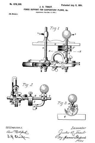
No. 688,969 – Plane (Solon R. Rust And Arthur E. Rust) (1901)

[paiddownloads id=”559″]688969


UNITED STATES PATENT OFFICE.

_________________

SOLON R. RUST AND ARTHUR E. RUST,
OF PINE MEADOW, CONNECTICUT.

PLANE.

_________________

SPECIFICATION forming part of Letters Patent No. 688,969, dated December 17, 1901.
Application filed June 25, 1900. Serial No. 21,440. (No model.)

_________________

To all whom it may concern:

Be it known that we, SOLON R. RUST and ARTHUR E. RUST, of Pine Meadow, in the county of Litchfield and State of Connecticut, have invented a new and useful lmprovement in Planes; and we do hereby declare the following, when taken in connection with the accompanying drawings and the letters of reference marked thereon, to be a full, clear, and exact description of the same, and which said drawings constitute part of this specification, and represent, in —

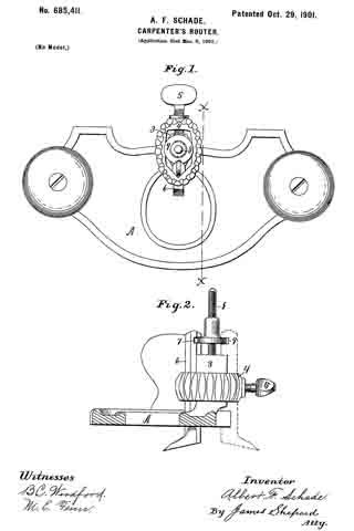
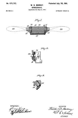
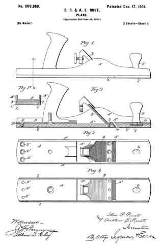
Figure 1, a view in side elevation of a plane constructed in accordance with our invention; Fig. 1a, a view thereof in transverse section on the line a b of the preceding figure; Fig. 2, a view of the plane in vertical central longitudinal section; Fig. 3, a plan view of the body of the plane stripped of all other parts; Fig. 4, a reverse plan view thereof; Fig. 5, a plan view of the removable sectional wooden face, the sections of which are separated from each other; Fig. 6, a view in transverse section on the line c d of Fig. 5; Fig. 7, a plan view of the removable sectional metal face of the plane with the sections drawn apart; Fig. 8, a view in transverse section on the line e f of the preceding figure.

Our invention relates to an improvement in that class of bench-planes designed for smoothing as distinguished from beading or rabbeting, and more particularly to smoothing-planes having metal bodies, the object being to produce at a low cost for manufacture a simple and strong plane constructed with particular reference to its adaptation to have a metal or a wooden face applied to it interchangeably, so as to readily adapt it to be used in situations requiring wooden faces as well as in situations requiring metal faces.

With these ends in view our invention consists in a plane having certain details of construction and combinations of parts, as will be hereinafter described,and particularly recited in the claims.

In carrying out our invention as herein shown the metal body A of the plane has cast integral with it an inclined cutter-supporting bed B, the opposite edges of which are supported or trussed by longitudinal flanges A’, rising from the opposite edges of I the upper face of the body. As shown, these flanges extend throughout the length of the body for increasing the strength thereof; but this is not essential. These flanges A’, as shown, are raised at points opposite the bed B, but elsewhere are straight and uniform in height. The said bed is provided for supporting the cutter, (not shown,) which may be of the usual construction and which is secured in place and adjusted in any desired manner. For the purpose of casting the said integral cutter-supporting bed without the use of cores a large casting-opening A2, which is located directly below the bed, is formed. This opening performs no function in the completed plane, but, as aforesaid, permits the body A to be cast without the use of a core, whereby the expense of producing the plane is greatly reduced. The body. A is also formed with a throat-opening A2, located directly in front of the casting-opening aforesaid and permitting the shavings removed by the cutter to escape upward through the plane.

To adapt the plane to be used in situations requiring wooden as well as metal faces, we design to provide each plane-body with interchangeable faces made of wood and of metal, respectively, these faces being constructed to correspond in size to the lower face of the body, so as to completely cover the casting-opening A2, formed therein.
These removable faces of wood and metal may be formed in one piece or in sections, as desired. As an illustration of their construction we have shown a sectional wooden face composed of a long rear section C and a short forward section C’. The said wooden section C is secured in place by screws D passing downward into it through the body of the plane, which for that purpose is formed with screw-holes D’, while the forward section is adjustably secured in place by means of a handle E, having a threaded stud F passing downward through an elongated slot G, formed in the forward portion of the body. The stud F is entered into the said forward section C’, which by turning the handle E is clamped against the forward end of the lower face of the body, so as to be held firmly in place; but as the adjacent ends of the two sections wear so as to unduly increase the opening H, Fig. 2, between them below the throat-opening A3 the forward section is moved rearwardly, so as to take up this wear by loosening the handle E.

As shown in Fig. 1a of the drawings, the lower face of the body is provided with two parallel centering-flanges I I, the inner faces of which are beveled and which insure the centering of the removable face when it is applied to the body; but these flanges are not necessarily employed, although we prefer to use them. To coact with the beveled inner faces of the flanges I I, the upper corners of the sections C and C’ are beveled, as shown at c in Figs. 1a and 6. When the removable face is made in sections, we preferably form the forward sections with two rearwardly-extending fingers J J, Fig. 5, which extend across the ends of the throat-opening A3, so as to prevent the shavings from clogging.

The removable metal face of the plane shown in Figs. 7 and 8 of the drawings comprises a long rear section K and a short forward section K These sections are reinforced and strengthened by the formation upon their upper faces of longitudinal side ribs L L and a longitudinal central rib L’. The rib L’ is enlarged near its ends to form posts L2 L2, which are internally threaded for the reception of the screws which hold it in place by passing down through the body of the plane, while the rib L’ of the forward section K is formed with a corresponding post L3 for the reception of the threaded stud F of the handle E. As shown in Fig. 8, the upper outer corners of the side ribs L of the sections K K’ are beveled, as at k, for coaction with the beveled inner faces of the centering-flanges I of the body of the plane.

Having fully described our invention, what we claim as new, and desire to secure by Letters Patent, is —

1. In a bench-plane, the combination with a metal body having an integral cutter-supporting bed both edges of which are supported or trussed by the body which is formed with a casting-opening located directly beneath the said bed, of a removable face adapted to be applied to the lower face of the said body to which it corresponds, and extending entirely over the said casting-opening.

2. In a bench-plane, the combination with a metal body having an integral cutter-supporting bed, both edges of which are supported or trussed by the body which is formed with a casting-opening located directly beneath the said bed, of a removable sectional face adapted to be applied to the lower face of the said body to which it corresponds in size, and extending entirely over the said casting-opening.

3. In a bench-plane, the combination with a metal body having an integral cutter-supporting bed both edges of which are supported or trussed by the body which is formed with a casting-opening located directly beneath the said bed, and with a throat-opening located in front of the said casting-opening, of a removable sectional face adapted to be applied to the lower face of the body so as to entirely cover the said casting-opening, and comprising a forward section which is longitudinally adjustable for taking up wear at the said throat-opening.

4. In a bench-plane, the combination with a metal body having an integral cutter-supporting bed both edges of which are supported or trussed by the body which is formed with a casting-opening located directly beneath the bed, of removable interchangeable metal and wooden faces adapted to be applied to the lower face of the body to which they correspond in size and the said casting-opening in which they entirely close.

5. In a bench-plane, the combination with a metal body having an integral cutter-supporting bed both edges of which are supported or trussed by the body which is formed with a casting-opening located directly beneath the bed and with a throat-opening located in front of the said casting-opening, of a removable sectional face adapted to be applied to the lower face of the body to which it corresponds in size, and the said casting-opening in which it entirely closes, the forward section of the said face being made longitudinally adjustable for taking up wear at the said throat-opening, and formed at its rear end with rearwardly~extending lugs which extend across the said throat-opening.

In testimony whereof we have signed this specification in the presence of two subscribing witnesses.

SOLON R. RUST.
ARTHUR E. RUST.

Witnesses:
WILLIAM McALPINE,
E. L. MORLEY.

No. 685,411 – Carpenter’s Router (Albert F. Schade) (1901)

[paiddownloads id=”558″]685411


UNITED STATES PATENT OFFICE.

_________________

ALBERT F. SCHADE, OF NEW BRITAIN, CONNECTICUT, ASSIGNOR TO
STANLEY RULE AND LEVEL COMPANY, OF NEW BRITAIN, CONNECTICUT.

CARPENTER’S ROUTER.

_________________

SPECIFICATION forming part of Letters Patent No. 685,411, dated October 29, 1901.
Application filed March 6, 1901. Serial No. 50,130. (No model.)

_________________

To all whom it may concern:

Be it known that I, ALBERT F. SCHADE, a citizen of the United States, residing in New Britain, in the county of Hartford and State of Connecticut, have invented certain new and useful Improvements in Carpenters’ Routers, of which the following is a specification.

My invention relates to improvements in carpenters’ routers; and the object of my improvement is to provide simple and efficient means for adjusting the cutter.

In the accompanying drawings, Figure 1 is a plan view of my router; and Fig. 2 is a sectional side elevation, the bed plate or frame being in vertical section on the line x x of Fig. 1.

The bed plate or frame A, tool-post 3, yoke 4, and set-screw 5 are of an ordinary and well-known construction. The cutter 6 is also of an old form, excepting as I provide a recess or notch 7 in its rear side near its upper end. In the center of the tool-post 3 and projecting upwardly therefrom is the adjusting-screw 8, rigidly and permanently affixed thereto or formed thereon, so as to constitute an immovable part thereof. Upon this screw is the adjusting-nut 9, preferably having a roughened or knurled edge for convenience of manipulation. This nut is of a diameter so large as to project into the path of the upper end of the cutter 6, whereby the adjusting-nut 9 and the cutter 6 may be assembled with the edge of the nut projecting into the recess or notch 7 in the cutter 6, as best shown in Fig. 2.

It will be readily seen that the cutter may be adjusted either up or down by turning the adjusting-nut 9; also, that the parts may be assembled when desired with the adjusting-nut above the notch in the cutter or wholly removed, so that the cutter may be used without any adjusting mechanism. The cutter 6 may also be placed in the reverse position on the back side of the post, as indicated by broken lines in Fig. 2, and the same adjusting mechanism is adapted for use with the cutter in this reversed position. The construction is simple and inexpensive, and the improved device is very convenient for effecting a fine adjustment, while it in no way interferes with any of the ordinary uses of the router.

I claim as my invention —

The combination of the bed-plate, the double-faced tool-post, projecting upwardly above the said bed, the cutter fitted to slide vertically cn the sides of the said tool-post, means for confining the said cutter in place on the said tool-post, the adjusting-screw 8, centrally mounted in the upper end of the said tool-post and projecting upwardly therefrom, and the adjusting-nut 9, mounted on the said adjusting-screw and operatively connected with the upper end of the said cutter, whereby the said adjusting mechanism may be used when the cutter is placed on either side of the said tool-post, substantially as described.

ALBERT F. SCHADE.

Witnesses:
H. S. WALTER,
E. G. HOFFMAN.

No. 682,958 – Plane (Thomas M. Seeds, Jr., And Martin Frings) (1901)

[paiddownloads id=”557″]682958


UNITED STATES PATENT OFFICE.

_________________

THOMAS M. SEEDS, JR., AND MARTIN FRINGS,
OF PHILADELPHIA, PENNSYLVANIA.

PLANE.

_________________

SPECIFICATION forming part of Letters Patent No. 682,958, dated September 17, 1901.
Application filed April 12, 1901. Serial No. 55,511. (No model.)

_________________

To all whom it may concern:

Be it known that we, THOMAS M. SEEDS, Jr., and MARTIN FRINGS, citizens of the United States, and residents of Philadelphia, in the county of Philadelphia and State of Pennsylvania, have invented a new and Improved Plane, of which the following is a full, clear, and exact description.

This invention relates to a plane adapted particularly for smoothing floors, but applicable for use in connection with all plane surfaces.

The invention comprises certain peculiar features of construction by which the plane is carried on a wheeled frame and pushed over the floor through the medium of a long handle, thus enabling the operator to stand upright at his work.

This specification is a specific description of one form of the invention, while the claims are definitions of the actual scope thereof.

Reference is to be had to the accompanying drawings, forming a part of this specification, in which similar characters of reference indicate corresponding parts in all the views.

Figure 1 is a longitudinal section of the invention. Fig. 2 is a cross-section thereof; and Fig. 3 is a detail view of one of the dogs, which will be hereinafter described.

a indicates the frame or carriage of the device. This frame is formed with cavities a’
therein, in which are located wheels b, these wheels supporting the frame, andthe cavities a’ being closed at the top to prevent shavings from entering the cavities and clogging the wheels. The frame a has an elastic bead or buffer a2 run around it to prevent marring the woodwork of the building, and at the front portion of the frame is arranged a brush a3, which is adapted to sweep away the dust and other gritty substances prior to the engagement of the blade with the wood.

c indicates the handle, which has a fork at its lower end pivotally connected with the frame a, the handle extending upward within convenient reach of the user, so that the plane may be pushed along much after the manner of the well-known hand lawn-mower.

d indicates a block which is set loosely within the frame a. This block is provided with pins e, which are fastened rigidly thereto and which are projected upward through cross-bars f The cross- bars fare secured rigidly to the frame a by latches f’, which are removably engaged in keepers f2, secured to the frame. Springs e’ bear between the cross-bars f and the block cl and serve to push the block downward. This block cl carries a blade g, which blade is held in the block by a wedge lt. The block d is suitably orificed, as indicated at d’, to receive the blade g and wedge h, so that as the device is moved along the floor the blade in engaging therewith will cut the shavings and throw them into and through the orifice in the block.

The apparatus is adapted to be pushed along on its wheels in the direction desired, and its operation in other respects is very much the same as the usual hand-plane. The block d bears on the ground, and the springs e’ serve to hold the block down, with the blade g properly engaged with the floor. The brush a3 prevents gritty substances from encountering the blade. By manipulating the latches f’ the cross-bars f may be removed from the frame and the block d, with its attached parts, taken out.

Having thus described our invention, we claim as new and desire to secure by Letters Patent —

1. A planer, comprising a wheeled frame, a block movably mounted thereon, means pressing the block downward and a planing-blade held by the block.

2. A planer, comprising a wheeled frame, a block set loosely therein, a spring pressing the block downward, and a planing -blade held by the block.

3. A plane, comprising a wheeled frame, a block mounted loosely therein, a planing-blade held by the block, a cross-bar engaged with the frame, a latch for removably holding the cross-bar in place, and a spring bearing between the cross-bar and block to press the block downward.

In testimony whereof we have signed our names to this specification in the presence of two subscribing witnesses.

THOMAS M. SEEDS, JR.
MARTIN FRINGS.

Witnesses:
NORMAN H. STEVENS,
W. L. STEVENS.

No. 680,056 – Plane (Edward S. Marks) (1901)

[paiddownloads id=”556″]680056


UNITED STATES PATENT OFFICE.

_________________

EDWARD S. MARKS, OF AUBURN, NEW YORK,
ASSIGNOR TO OHIO TOOL COMPANY, OF NEW YORK.

PLANE.

_________________

SPECIFICATION forming part of Letters Patent No. 680,056, dated August 6, 1901.
Application filed December 10, 1900. Serial No. 39,447. (No model.)

_________________

To all whom it may concern:

Be it known that I, EDWARD S. MARKS, a citizen of the United States, and a resident of the city of Auburn, in the State of New York, have invented certain new and useful Improvements in Planes, of which the following is a specification.

This invention relates to the devices by which the chisel is adjusted in relation to the plane-stock; and it consists in certain new constructions and arrangements of the parts by which this adjustment is effected.

In the drawings, Figure 1 is a plan of a plane-stock provided with my improvements. Fig. 2 is a vertical section upon the line x y of Fig. 1, and Fig. 3 shows the lever separately.

Similar reference-letters indicate like parts in the several views.

In the drawings, A is the plane-stock. B is the chisel, which is secured by means of the cap C, which is held by the screw D and is locked by means of the lever E, pivoted at e and carrying a cam e’.

The foregoing parts are of usual construction.

Upon the plane-stock a carriage F is pivoted at f, which oscillates in the horizontal plane across the bed g. The carriage F is furnished with a slide h, seated thereon, and actuated by a screw K, which extends to the rear of the carriage F and is turned by its head L. A projection n upon the slide h, engages a corresponding depression or aperture m, in the chisel and holds the latter in position.

In operation the lengthwise adjustment of the chisel is performed by rotating the screw K, and by moving the carriage F upon its pivot f crosswise the lateral adjustment of the chisel is effected.

Wliat I claim as new, and desire to secure by Letters Patent, is —

In a plane and in combination; a plane-stock; a chisel mounted therein; means for clamping said chisel in said stock; a carriage pivotally mounted on said plane-stock so as to permit a lateral adjustment of said carriage and the parts supported thereby; a slide mounted on said pivoted carriage, and engaging said chisel ; and means carried by said carriage to adjust said slide and chisel longitudinally.

Signed at Auburn, New York, this 6th day of December, A. D. 1900.

EDWARD S. MARKS.

Witnesses:
H. D. PARSELL,
FREDERICK I. ALLEN.

No. 680,055 – Plane (Edward S. Marks) (1901)

[paiddownloads id=”555″]680055


UNITED STATES PATENT OFFICE.

_________________

EDWARD S. MARKS, OF AUBURN, NEW YORK,
ASSIGNOR TO OHIO TOOL COMPANY, OF NEW YORK.

PLANE.

_________________

SPECIFICATION forming part of Letters Patent No. 680,055, dated August 6, 1901.
Application filed December 4, 1900. Serial No. 38,705. (No model.)

_________________

To all whom it may concern:

Be it known that I, EDWARD S. MARKS, a citizen of the United States, and a resident of the city of Auburn, in the county of Cayuga and State of New York, have invented certain new and useful Improvements in Planes, of which the following is a specification.

This invention consists in certain new devices used to regulate the position of the chisel in relation to the plane-stock; and its object. is to furnish means for readily adjusting the chisel both longitudinally and laterally.

In the drawings, Figure 1 is a plan of a plane provided with my improvements and with the chisel and retaining-cap removed; and Fig. 2 is a sectional view upon the line x y of Fig. 1, showing the chisel and cap in position.

Similar reference-letters indicate like parts in both views.

In the drawings, A is the plane-stock, B is the chisel, and C the cap-iron, which is secured under the cross-bar D by means of the screw E.

The chisel B is provided with a rack b, and a pinion-section d, pivoted at f and operated by a lever K, engages it. The dotted lines of Fig. 2 indicate different positions which this lever may occupy in the vertical plane. By this means the chisel is moved in the direction of its length as required.

The carriage g, which supports the pivot f, is pivotally secured at h, so that it may be moved laterally, and the dotted lines of Fig. 1 show dilierent positions which it may occupy in the horizontal plane, the upright ears g’, rising from the carriage g, straddling the rack b on the under side of the chisel B and lengaging the parts for lateral adjustment, as shown in Fig. 2, the segment m upon the plane-stock furnishing a support for it in its different positions.

By the above-described means the chisel B is readily adjusted either vertically or laterally, as desired.

What I claim as new, and desire to secure by Letters Patent, is —

1. In a plane and in combination, a plane-stock, a chisel, means for clamping said chisel in said plane-stock, a carriage having a vertical pivotal connection with said plane-stock, a lever carried by and having a horizontal pivotal connection with said carriage to shift said carriage laterally on its pivot, means on said carriage to engage and shift said chisel laterally, and means on said pivoted carriage-lever to engage said chisel and shift it longitudinally.

2. In a plane and in combination, a plane-stock, a chisel, means for clamping said chisel in said plane-stock, a carriage having a vertical pivotal connection vvith said plane-stock, a segment formed on said stock to support said carriage, a lever carried by and having a horizontal pivotal connection with said carriage to shift said carriage laterally on its pivot, upright ears on said carriage to engage and shift said chisel laterally, and means on said pivoted carriage-lever to engage said chisel and shift it longitudinally.

Signed at Auburn, New York, this 1st day of December, A. D. 1900.

EDWARD S. MARKS.

Witnesses:
HENRY D. PARSELL,
FREDERICK I. ALLEN.

No. 679,702 – Spokeshave (Walter D. Murray) (1901)

[paiddownloads id=”554″]679702


UNITED STATES PATENT OFFICE.

_________________

WALTER D. MURRAY, OF PORTLAND, MAINE, ASSIGNOR,
OF ONE-HALF TO WALTER ACKROYD, OF SAME PLACE.

SPOKESHAVE.

_________________

SPECIFICATION forming part of Letters Patent No. 679,702, dated July 30, 1901.
Application filed May 31, 1900. Serial No. 18,627. (No model.)

_________________

To all whom it may concern:

Be it known that l, WALTER D. MURRAY, a citizen of the United States, residing at Portland, in the county of Cumberland, in the State of Maine, have invented certain new and useful lmprovements in Spokeshaves, of which the following is a specification.

This invention relates to that class of wood-working planes known as spokeshaves.

One object of the invention is to provide a spokeshave with a detachable reversible sole-piece, either edge of which may be used to vary the form of the spokeshave to adapt it for either concave or straight work.

Another object of the invention is to provide simple and effective means for raising and lowering the blade, whereby either end thereof may be moved as desired independently of the other to seen re accuracy of adjustment.

Another object is to provide improved handles for the spokeshave for insuring a better grip and a steadier working tool.

Figure 1 of the accompanying drawings represents a front elevation of this spokeshave. Fig. 2 represents a rear elevation thereof. Fig. 3 represents a central transverse section on line 3 3 of Fig. 1. Fig. 4 represents a similar section with the sole-piece reversed. Fig. 5 represents a perspective view of the detachable sole-piece. Fig. 6 represents a perspective view of the blade or cutter. Fig. 7 represents a rear elevation of the stock, the detachable sole-piece being removed. Fig. 8 represents another form of connection between the blade and the adjusting-screws therefor. Fig. 9 represents an end view of the stock, one of the handles being shown in section on line 9 9 of Fig. 1.

The same reference numbers indicate corresponding parts in all the figures.

In the form of spokeshave illustrated in the accompanying drawings a body or stock 10, having handles 20 and 30 at its opposite ends, is recessed at its back to receive a detachable sole-piece 40. The recessing of the stock forms a rear bed for the blade and shoulders 11 and 12, against which the ends of the sole-piece 40 abut. These shoulders 11 and 12 are provided with screw-threaded sockets 13 and 14, adapted to receive headed screws 50 and 60, respectively, the object of which will be hereinafter described. This stock is provided with a slot 17, through which the shavings pass. Means are provided on the stock and sole-piece for adjusting the latter incorrect position, and these means may consist of lags on one part and notches in the other. When constructed as here shown, the stock 10 is provided at the opposite ends of its recessed bed with lugs 15 and 16, adapted to engage notches 41 and 42, formed in the opposite ends of the sole-piece 40, whereby the proper adjustment of the sole-piece is accomplished.

The detachable sole-piece 40 is preferably constructed with its opposite edges in different forms, being shown as provided with a flat edge 43 and with a rounded edge 44,and either edge may be used to vary the shape of the spokeshave, as desired, by reversing the sole-piece.

Suitable means are provided for fastening the detachable sole-piece to the stock. In the form shown this sole-piece 40 has a screw-threaded shank 45 extending at right angles from the center of its inner face. This shank 45 may consist of a screw passed through the sole-piece or it may form a part of a bolt, the sole-piece 40 constituting the head thereof. This shank or bolt 45 extends through a perforation 18 in the stock 10, and the outer end thereof is engaged by a thumb-nut 46, which firmly clamps the sole-piece to the stock.

A blade 70, having a longitudinal slot 71 therein, is disposed in the recessed portion of the stock; 10, between it and the sole-piece 40. The bolt 43 of the sole-piece passes through the slot 71 before entering the perforation 18 of the stock, and the screwing down of the thumb-nut 46 thereon clamps the knife 70 firmly in position between the stock and the sole-piece. This blade 70 is provided at its opposite ends, near its top, with means for engaging the adjusting-screws 50 and 60, respectively. In the form shown in Figs. 1 and 2 these means consist of notches 72 and 73. In the form shown in Fig. 8 they consist of lateral lugs 74, which engage grooved or double heads 51 and 61 on the adjusting-screws. This blade may be adjusted at any desired height by simply turning the screws in the direction desired, and either end thereof may be independently raised or lowered to secure accuracy of adjustment by raising or lowering the screw connected therewith. Concave recesses 21 and 31, disposed substantially in a vertical plane and at right angles to the sole of the shave, are formed at the ends of the stock and extend through the adjacent portions of the handles 20 and 30, on the rear side of the latter. These recesses serve as finger-rests for the index-fingers when the shave is grasped in the hands and afford a better grip for the operator and a steadier working tool.

Either the means for adjusting the blade, the peculiar form of handles, or the detachable sole-piece may be applied to any adaptable form of spokeshave.

I claim as my invention —

1. A spokeshave having a detachable rear sole-piece serving as a clamp for the blade.

2. A spokeshave having a detachable reversible rear sole-piece.

3. A spokeshave having a reversible rear sole-piece provided with edges of different forms.

4. A spokeshave provided with a reversible rear sole-piece having edges of different forms, one of said edges being flat and the other rounded.

5. A spokeshave comprising a recessed stock, a blade adapted to fit in said recess, a reversible sole-piece also adapted to fit in said recess behind said blade, said stock being provided with means for engaging said sole-piece, and means for securing the blade and sole-piece to the stock.

6. A spokeshave comprising a stock provided with a recess at its back, a reversible sole-piece, adapted to fit in said recess, interlocking means on said stock and sole-piece, a blade disposed between said stock and sole-piece, and means for securing said sole-piece and blade to said stock.

7. A spokeshave comprising a stock provided vvith a recess at its back and lugs at opposite ends of said recess, a reversible sole-piece adapted to fit in said recess and provided with notches adapted to engage said lugs, a blade disposed between said sole-piece and stock, and means for securing said blade and sole-piece to said stock.

8. A spokeshave comprising a recessed stock having a perforation therein, a detachable rear sole-piece having a bolt attached thereto and adapted to extend through said perforation, a thumb-nut adapted to screw on said bolt and fasten the sole-piece in position, and a blade clamped between said sole-piece and stock.

9. In a spokeshave the combination of a stock provided with a blade-bed and with screvv-sockets adjacent to opposite ends of said bed, a blade provided with notches at its opposite ends, means for clamping said blade to said bed, and adjusting-screws disposed in said sockets and provided with heads engaging said lateral notches.

10. A spokeshave comprising, a stock and handles extending from opposite ends thereof, vertical concave recesses being formed at the ends of the stock and adjacent portions of the handles on the rear side of the latter, which recesses serve as rests for the index-fingers when the shave is grasped by the hands.

WALTER D. MURRAY.

Witnesses:
ALICE H. SULIVAN,
JOSEPH E. DANAHER.

No. 679,424 – Plane (Ludwig Kemline) (1901)

[paiddownloads id=”553″]679424


UNITED STATES PATENT OFFICE.

_________________

LUDWIG KEMLINE, OF PINOLE, CALIFORNIA.

PLANE.

_________________

SPECIFICATION forming part of Letters Patent No. 679,424, dated July 30, 1901.
Application filed October 27, 1900. Serial No. 34,625. (No model.)

_________________

To all whom it may concern:

Be it known that I, LUDWIG KEMLINE, a citizen of the United States, and a resident of Pinole, in the county of Contra Costa and State of California, have invented a new and Improved Plane, of which the following is a full, clear, and exact description.

The purpose of this invention is to provide a plane or other tool with a handle which may be adjusted transversely of the plane, so as to place the hand of the user in any position desired with respect to the transverse extent of the plane. By these means the operator may avoid bruising his hands or otherwise interfering with the work when it is of such character as will make it inconvenient to use the tool with the handle in the middle thereof.

This specification is the disclosure of one form of the invention, while the claims define the actual scope thereof.
Reference is to be had to the accompanying drawings, forming a part of this specification, in which similar characters of reference indicate corresponding parts in both views.

Figure 1 is a side view of the invention with parts in section, and Fig. 2 is a section on the line 2 2 of Fig. 1.

The plane is constructed in the usual manner, except that the body is formed with two transverse grooves a, which open at the upper side of the body and which are undercut, as shown. The cross-sectional form of the grooves a is immaterial so long as the opening at the top of the grooves is of less width than the opening below the top. The purpose of this is to hold in the grooves the blocks b in such a manner as to prevent the blocks from moving upward or transversely out of the grooves. These blocks are freely movable longitudinally of the grooves, however, and the handle c of the plane is attached to the blocks through the medium of a face-plate d and screws e, passing through the base-plate and into the blocks, as best shown in Fig. 2. The base-plate d is provided with transverse ribs d’, which fit in the upper sides of the grooves a, and serve to assist in holding the base-plate in position. The base-plate is preferably of metal and fastened to the handle c by screws or other devices, as shown.

Having thus described my invention, I claim as new and desire to secure by Letters Patent —

1. A plane or analogous tool having an undercut groove in the upper side thereof, said groove extending transversely of the plane, a block adjustably mounted in the groove, a handle, a base-plate on which the handle is mounted, and a fastening device extending between the base-plate and block to bind the block against the walls of the groove and adjustably hold the handle.

2. A plane or analogous tool having two undercut grooves formed in its upper side, said grooves extending transversely of the plane, a block adjustable in each groove, a base-plate extending from one groove to the other and having ribs fitting in the grooves, fastening devices extending between the block and the base-plate, and a handle fastened to the base-plate.

In testimony whereof I have signed my name to this specification in the presence of two subscribing witnesses.

LUDWIG KEMLINE.

Witnesses:
JAMES SILVAS,
A. McCULLOUGH.

No. 678,309 – Fence-Support For Carpenters’ Plows (Justus A. Traut) (1901)

[paiddownloads id=”552″]678309


UNITED STATES PATENT OFFICE.

_________________

JUSTUS A. TRAUT, OF NEW BRITAIN, CONNECTICUT, ASSIGNOR TO
STANLEY RULE & LEVEL COMPANY, OF SAME PLACE.

FENCE-SUPPORT FOR CARPENTERS’ PLOWS, &c.

_________________

SPECIFICATION forming part of Letters Patent No. 678,309, dated July 9, 1901.
Application filed Mar 6, 1901. Serial No. 50,015. (No model.)

_________________

To all whom it may concern:

Be it known that I, JUSTUS A. TRAUT, a citizen of the United States, residing in New Britain, in the county of Hartford and State of Connecticut, have invented certain new and useful Improvements in Fence-Supports for Carpenters’ Plows, &c., of which the following is a specification.

My invention relates to improvements in fence-supports for carpenters’ plows, beading and molding tools, etc.; and the object of my improvement is to furnish a support for the fence to assist the user in holding the tool in proper position relatively to the surface of the work.

In the accompanying drawings, Figure 1 is a plan view of a combination beading and molding tool, plow, &c., with my fence-support applied thereto. Fig. 2 is an end view of the same; and Fig. 3 is a sectional side elevation of a portion of the same, the plane of section being indicated by the line x x, Fig. 1.

A designates the stock or main portion of the tool, having two laterally projecting fence-rods 4 4, upon which the fence 5 is supported and adjustably held in position thereon by means of the set-screws 6. The said stock also has secured therein the beading-tool 7. These parts are all old and well known, and therefore any further description thereof is deemed unnecessary. It is also apparent that the detail construction of the minor parts is immaterial to the present invention, and any other known tool-stock having laterally-extended fence-rods and a fence supported thereon may be substituted as a known equivalent for the said stock and its minor parts.

An expert workman by proper effort can and does keep the tool in such a position when working that the fence-rods will be parallel to the surface of the wood operated upon; but in order to enable him to do so with greater ease than heretofore and also to better enable one of less skill in use of the tool to hold the tool in proper level position I employ the fence-support 8. Although I have in accordance with the usual phrase entitled my invention as an “Improvement in fence-supports for plows, &c.,” I do not thereby wish to imply that a fence-support of any kind for such tools was ever before known or used.

The preferred form of my fence-support is that of a cam or snail-shaped device having a perforated hub or socket 9 of a size to fit one of the fence-rods 4, preferably the forward one, so that it may swing or partially turn thereon to vary the height of its under face relatively to the fence and also that it may slide on the said rod for changing its position laterally whenever the fence is adjusted laterally on the said rod. I provide the said hub or socket 9 with a set-screw 10 for holding the support in the desired adjusted position.

The operator may set the support at first so as to bring its lowest and gaging face as much above the lower end of the beading or cutting tool as the depth of the cut to be made, and thus insure the proper position of the tool at the nnish of the beading or other work, or he may first set the support with its lower edge at about the same height as the end of the tool and then change the support by adjusting its face downwardly as the work progresses. In case the support is not wanted it can readily be wholly removed, leaving the tool in its original position.

While the snail or cam form of support herein shown is the preferred one as the most convenient construction for perfecting the desired adjustments, this particular form is not always necessary, as it is only essential that the device, whatever it may be, shall be capable of lateral adjustment on the fence-rods and also of vertical adjustment of its supporting-face relatively to the said rod.

I claim as my invention —

The herein-described fence-support for carpenters’ tools of the class employing fence-rods and a fence, the said support consisting of a cam-shaped device having a socketed hub fitted to one of the fence-rods, substantially as described.

JUSTUS A. TRAUT.

Witnesses:
H. S. WALTER,
ROBT. N. PECK.

No. 668,299 – Spokeshave (Justus A. Traut) (1901)

[paiddownloads id=”551″]668299


UNITED STATES PATENT OFFICE.

_________________

JUSTUS A. TRAUT, OF NEW BRITAIN, CONNECTICUT.

SPOKESHAVE.

_________________

SPECIFICATION forming part of Letters Patent No. 668,299, dated February 19, 1901.
Application filed October 29, 1900. Serial No. 34,012. (No model.)

_________________

To all whom it may concern:

Be it known that I, JUSTUS A. TRAUT, a citizen of the United States, residing in New Britain, in the county of Hartford and State of Connecticut, have invented certain new and useful Improvements in Spokeshaves, of which the following is a specification.

This invention relates to spokeshaves, and has for one object the provision of an improved tool which may be employed on various varieties of wood with good results and one in which the knife and the guard or throat-gage are adjustable in planes at right angles to each other; the back of the guard being formed with a plane face constituting a wall of the throat for the reception of the shavings, whereby the straight edge of said guard opposed to the knife may when injured or blunted be readily renewed by simply grinding said face.

A further object of the invention is the provision within the stock of the spokeshave of a chamber for the reception of shavings, the upper wall of said chamber being curved outwardly to facilitate the discharge of said shavings.

A further object of the invention is the provision, in connection with a spokeshave, of a guard or throat-gage, the working surface of which is convex both transversely and longitudinally.

In the accompanying drawings, Figure 1 is a plan view of my improved spokeshave, part of one of the handles being broken away. Fig. 2 is a side elevation, partially in section. Figs. 3 and 3a are transverse sections on line into of Figs. 1 and 2, showing different adjustments of the guard or throat-gage. Fig. 4 is a perspective view of the knife or cutter. Fig. 5 is a perspective view of the guard, and Fig. 6 is a perspective view of one of the bolts for adjustably securing the knife in position.

Similar characters designate corresponding parts throughout the several views.

Referring to the drawings, the numeral 5 designates the stock of my improved spoke-shave, having the usual handles 5′ 52 and provided with a chamber 6 (the wall 6′ of which is curved outward for a purpose hereinafter described) and with a forward straight portion 62.

Formed in the stock at each end of the chamber 6 are grooves 7, having rabbeted portions 7′, constituting guideways for the reception of flanges 8 on the ends of a knife or cutter 9, which is preferably of the “razor-blade” type and is slightly curved longitudinally, and fitted in said grooves 7 are the flat oblong heads 10′ of bolts 10, the threaded shanks of which pass through perforations in the stock and carry thumb-nuts 12, by turning which the heads 10′ may either be forced tightly against the flanges 8 of the cutter or released therefrom to permit said cutter to be adjusted, as desired. Cooperating with this cutter is a guard or throat-gage 13, slotted at 13′ for the reception of screws 14, which enter the stock, in virtue of which construction the guard may be adjusted transversely of the cutter to vary the dimensions of the throat in which the shavings enter between said parts.
It will be observed by reference to Figs. 3 and 3a that this guard is provided with a plane back 132, which terminates in a straight edge 133, and when this straight edge is blunted or otherwise injured by wear, as frequently happens, it can readily be restored by removing the guard and grinding the flat face 132, after which it can be replaced with said face in engagement with the corresponding flat face 62 of the stock. On its lower or grinding surface the guard is made convex both longitudinally and transversely, as at 15, and can therefore much more readily be applied to rounded surfaces of the work. The face 15, which extends outward from the edge 133, is joined to the back 132 by the curved surface, which at its upper portion becomes nearly or quite parallel to the back, forming a body of convenient thickness in which to locate the slots 13′.

By reference to Figs. 3 and 3a it will be seen that the knife 9 and guard 13 may be so adjusted with relation to each other that the cutting edge of the knife will be brought into line with and almost touch the straight edge of the guard, whereby a very fine shaving may be removed from the work, if desired.
This is especially important when cutting hard wood or across the grain and obviates to a large extent the danger of splitting the wood or of tearing out a splinter therefrom — accidents of frequent occurrence with the old styles of spokeshaves, in which the knife overlaps a beveled edge on the guard.

As is well known, chips or shavings entering the mouth between the guard and knife tend to curl or assume a helical form, and to aid them in this action they are caused to impinge against the curved wall 6’ of the chamber 6 and are by said wall guided and defiected toward the exterior of the stock.

By my improved construction it will be seen that the guard may be so adjusted that the edge of the knife may be brought into line with the straight edge 133 or caused slightly to overlap the same, if desired, thereby enabling the tool to be employed on various kinds of woods, either hard or soft, at pleasure, for, as is obvious, the height of the knife above the guide-surface and also the position of the cutting edge may be regulated with nicety to obtain a throat of the desired width.

As will be observed, the flat oblong heads 10′ of the bolts 10 extend equally on each side of said bolts, and as said heads snugly fill the grooves 7 of the stock the bolts are thus interchangeable and reversible, so that the parts may be disassembled and reassembled regardless of their original positions. Furthermore, the top surfaces of the heads of these bolts and the bearing-surface of the guard or throat-gage are flush with each other, so as to form a smooth working face for the tool.

Preferably the stock and its handles are formed of metal in an integral casting, although the invention is not limited in this respect.

My invention is not limited to the precise details illustrated and described, and modifications may be made in the shape of the parts without departure therefrom.

Having thus described my invention, what I claim is —

1. In a spokeshave, the combination with a chambered stock of a cutter secured in said stock; and a guard or throat-gage cooperating with said cutter and having a working face curved in two directions and a plane back adjacent to the curved surface, said guard being adjustable to bring the working surface of said gage substantially to a position in line with the edge of the cutter.

2. In a spokeshave, the combination, with a stock and its handles, said stock having a chamber with an outwardly-curved wall and also having grooves and guideways at the ends of said chamber, of a longitudinally-curved cutter having flanges fitted in the ways of said stock; bolts having heads in engagement with said flanges; a guard or throat-gage having a straight back portion adjustably secured to the forward wall of the stock, the working surface of said guard or throat-gage projecting from said back portion and being curved both longitudinally and transversely, and said gage being adjustable on the stock to bring its working surface substantially into line with the edge of the cutter, substantially as and for the purpose specified.

JUSTUS A. TRAUT.

Witnesses:
ROBT. N. PECK,
M. G. PORTER.