No. 871,001 – Bench-Plane (Ernest W. Smith) (1907)
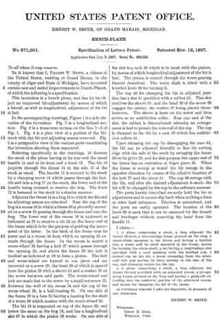
UNITED STATES PATENT OFFICE.
_________________
ERNEST W. SMITH, OF GRAND MARAIS, MICHIGAN.
BENCH-PLANE.
_________________
871,001. Specification of Letters Patent. Patented Nov. 12, 1907.
Application filed July 5, 1907. Serial No. 382,245.
_________________
To all whom it may concern:
Be it known that I, ERNEST W. SMITH, a citizen of the United States, residing at Grand Marais, in the county of Alger and State of Michigan, have invented certain new and useful Improvements in Bench-Planes, of which the following is a specification.
This invention is a bench plane, and has for its object an improved bit-adjustment by means of which a lateral, as well as longitudinal, adjustment of the bit is had.
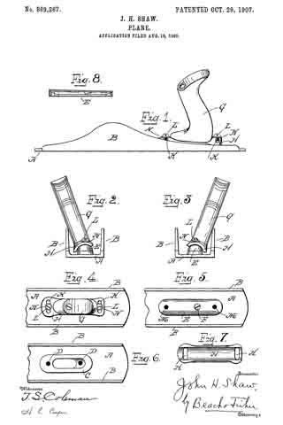
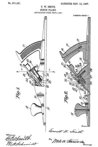
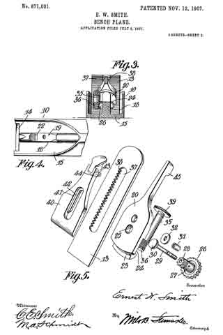
In the accompanying drawings, Figure 1 is a side elevation of the invention. Fig. 2 is a longitudinal section. Fig. 3 is a transverse section on the line 3–3 of Fig. 1. Fig. 4 is a plan view of a portion of the bit-stock with the bit and adjusting means removed. Fig. 5 is a perspective view of the various parts constituting the invention showing them separated.
Referring specifically to the drawings, 10 denotes the stock of the plane having at its rear end the usual handle 11 and at its front end a knob 12. The bit 13 projects through the throat 14 in the sole 15 of the stock as usual. The handle 11 is secured to the stock by a clamping screw 16 which passes through the handle and into a frog 17 on the stock, the lower end of the handle being recessed to receive the frog. The knob 12 is fastened to the stock in a similar manner.
Adjacent the throat 14 is a frog 18 to which the bit and its adjusting means are attached. Near the top of the frog is a recess 19 in which a frame 20 is pivotally mounted on a screw 21 passing through the frame and into the frog. The lower end of the recess 19 is undercut as indicated at 22 to receive a rib 23 on the lower end of the frame which is for the purpose of guiding the movement of the latter. In the back of the frame near its lower end is a recess 24 from which an opening 25 extends through the frame. In the recess is seated a worm-wheel 26 having a hub 27 which passes through the opening 25, and above the frame 20 the hub is toothed as indicated at 28 to form a pinion. The hub and worm-wheel are formed in one piece and are mounted on a screw 29, the head 30 of which is spaced from the pinion 28 with a sleeve 31 and a washer 32 on the screw between said parts. The worm-wheel and hub are made fast to the screw by a small set-screw 33. Between the wall of the recess 24 and the top of the worm-wheel 26, is a ball-bearing 34. On one side of the frame 20 is a boss 35 having a bearing for the shaft of a worm 36 which meshes with the worm-wheel 26.
The bit 13 is supported on top of the frame 20, and below the same on the frog 18, and has a longitudinal slot 37 in which the pinion 28 works. On one side of the slot is a rack 38 which is in mesh with the pinion, by means of which longitudinal adjustment of the bit is had. The pinion is rotated through the worm-gearing therein described. The worm shaft is fitted with a knurled knob 39 for turning it.
The cap 40 for clamping the bit in adjusted position has a slot 41 provided with a rabbet 42. This slot receives the sleeve 31, and the head 30 of the screw 29 engages the rabbet, the washer 32 being placed therebetween. The sleeve is loose on the screw and thus serves as an antifriction roller. Near one end of the slot, the rabbet is discontinued whereby an enlargement is had to permit the removal of the cap. The cap is clamped to the bit by a cam 43 which has antifriction rollers 44.
Upon releasing the cap by disengaging the cam 43, the bit can be adjusted laterally to line its cutting edge with the sole of the stock by swinging the frame 20 on its pivot 21, and for this purpose the upper end of the frame has an extension or finger piece 45. When the frame is swung as stated the bit swings in the opposite direction by reason of the relative location of the hub 27 and the pivot 21. The cap 40 swings with the bit, and after the desired adjustment is made the bit will be clamped by the cap in the ordinary manner.
The parts herein described securely hold the bit at adjustment and it cannot slip back when striking a knot or other hard substance. Friction is minimized, and the parts are easily operated. The location of the knob 39 is such that it can be operated by the thumb and forefinger without removing the hand from the handle 11.
I claim:–
1. A plane comprising a stock, a frog adjacent the throat thercof, a bit-carrying frame pivoted on the frog, a worm-wheel mounted in the frame and having a toothed hub, a worm and its shaft mounted in the frame, means for turning the worm-shaft, a bit having a longitudinal slot provided with a rack meshing with the toothed hub, a slotted cap on the bit, a screw extending from the aforesaid hub and having its head seating in the slot ot the cap, and clamping means for the cap.
2. A plane comprising a stock, a frog adjacent the throat thereof provided with an undercut recess, a bit-carrying frame pivoted on the frog and having a guide-rib extending into the undercut portion of the aforesaid recess, and means for clamping the bit to the frame.
In testimony whereof I affix my signature, in presence of two witnesses.
ERNEST W. SMITH.
Witnesses:
COLIN D. DOIG,
WILLIAM VION.