No. 107,765 – Improvement In Splint-Planes (Philander N. Drake And David Drummond) (1870)

[paiddownloads id=”160″]107765


United States Patent Office.


PHILANDER N. DRAKE AND DAVID DRUMMOND, OF MCGREGOR, IOWA.

Letters Patent No. 107,765, dated September 27, 1870.
_________________

IMPROVEMENT IN SPLINT-PLANES.

_________________

The Schedule referred to in these Letters Patent and making part of the same.

_________________

To all whom it may concern:

Be it known that we, PHILANDER N. DRAKE and DAVID DRUMMOND, of McGregor, in the county of Clayton and in the State of Iowa, have invented certain new and useful Improvements in Splint-Plane or Slat-Cutter; and do hereby declare that the following is a full, clear, and exact description thereof, reference being had to the accompanying drawing and to the letters of reference marked thereon, making a part of this specification.

Our invention relates to that kind of planes used in cutting thin strips or slats for rustic shades, and other purposes, and consists —

First, in placing the cutter under the bottom of the plane, level with the edge of the board from which the strips or slats are to be cut;

Second, in the construction of the mechanism for holding the cutter in its place; and

Third, in the construction of the mechanism for regulating the thickness of the strips or slats to be cut.

In order to enable others skilled in the art to which our invention appertains to make and use the same, we will now proceed to describe its construction and operation, referring to the annexed drawing, in which —

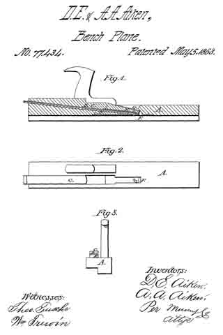
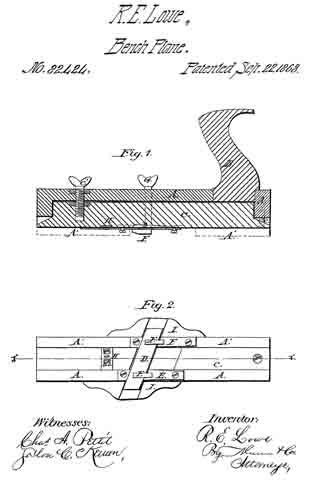
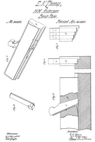
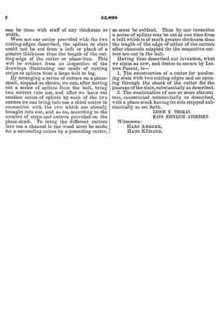
Figure 1 is a side view, part in section, of our plane;
Figure 2 is a transverse vertical section; and
Figure 3, a bottom view of the same.
Figure 4 shows the end of the cutter, with the channel-plates in the plane.

A represents the body of our plane provided with a handle, B.

Along one side of the body A is secured a bar, C, projecting below the plane a suitable distance to form a guard or guide for the tool.

Between the under side of the plane A and the bar C is formed a groove, in which the inner edge of the cutter D is inserted, said cutter being laid level under the lower side, or against the lower side of the plane A.

The cutting-tool D is held by means of a stirrup, E, constructed as shown in fig. 2, and passed up through the plane A, with a screw-shank at its upper end, which projects above the plane.

On this screw-shank is placed a thumb-nut, G, by means of which the stirrup is raised so as to firmly bind the cutting-tool. The pitch of the cutting-edge of said tool is regulated by means of two inclined screws, I I, passing through the plane A and bearing against the upper surface of the cutter, one on each side in front of the stirrup E.

The tool-bit being on a level with the edge of the board, it splits with less liability to break the fiber on the back of the slat. When it is to be taken out to sharpen, it can be put back to its place accurately and cut all the work of uniform thickness.

The two screws, I I, forcing the cutting-edge of the cutter to the desired position for uniform thickness, may, of course, remain in the same position for any length of time without change, even though the cutter is taken out and replaced again.

In the channel on the under side of the plane A, between it and the cutter D, are placed three channel-plates, a, b, and d, the relative positions of which are plainly indicated in fig. 4. The object of these plates is to further enable us to vary the thickness, if we desire to do so.

The back or upper side ofthese plates may be provided with inclines to enable them to be pushed forward or back.

The middle plate d is made so that it can readily be taken out and another of different size substituted.

Having thus fully described our invention,

What we claim as new, and desire to secure by Letters Patent, is —

The combination, with the stock A, of the flat-laid tool D, channel-plates a b d, stirrnp E, nut G, and screws I I, all constructed to operate substantially as set forth.

In testimony that we claim the foregoing, we have hereunto set our hand and seals this 26th day of March 1870.

PHILANDER N. DRAKE. [L. S.] DAVID DRUMMOND. [L. S.]

Witnesses:
A. J. JORDAN,
ORLANDO McCRAREY.

No. 77,434 – Improvement In Splint-Planes (D.E. Aiken And A.A. Aiken) (1868)

[paiddownloads id=”138″]77434


United States Patent Office.


D. E. AIKEN AND A. A. AIKEN, OF ADRIAN, MICHIGAN.

Letters Patent No. 77,434, dated May 5, 1868.
_________________

IMPROVEMENT IN SPLINT-PLANES.

_________________

The Schedule referred to in these Letters Patent and making part of the same.

_________________

ALL WHOM IT MAY CONCERN:

Be it known that we, D. E. AIKEN and A. A. AIKEN, of Adrian, in the county of Lenawee, and State of Michigan, have invented a new and improved Plane; and we do hereby declare that the following is a full, clear, and exact description thereof, which will enable others skilled in the art to make and use the same, reference being had to the accompanying drawings, forming part of this specification.

The present invention relates to a new and improved plane, or machine for the cutting of slats to be used more particularly in making curtains; and the invention consists in making the throat of the cutter in the wedge, and also in the use of a spring within the throat, so constructed as to cause one slat to push another out, whereby the throat and bit are left free, and all danger of the throat becoming clogged rendered impossible.

This spring also acts to press the slat uniformly and closely up against the bit, thus leaving the slat smooth and straight, and is arranged so as to be susceptible of adjustment for thick or thin slats.
In the accompanying plate of drawings our improved plane is illustrated —

Figure 1 being a central longitudinal vertical section through the plane,
Figure 2 a plan or top view, and
Figure 3 a view of the plane at one end.

Similar letters of reference indicate corresponding parts.

A, in the drawings, represents the stock to the plane made upon its running-face of a right-angular shape, as shown in fig. 3 by an end view.

B, the cutter arranged in the stock A, as in ordinary planes, and there secured by driving a wedge, C, into the stock over the cutter, this wedge being cut out upon its under side to form or leave a passage or throat, D, between it and the top ofthe cutter B.

E, a bent spring secured in wedge C along its under side, with its loose end toward the opening F in the running-surface of the plane, which spring is susceptible of adjustment by means of a set-screw, G, in the wedge C, in proper position to bear therein.

Among the many advantages of our improved plane or slat-cutter may be here mentioned that for the following reasons it is superior to all others:

It is simple, cheap, and easily kept in order, runs remarkably easy, makes a superior slat, lighter, smoother, and more durable than any other, producing what is called a wafer-slat, which is more durable, for the reason that it does not cut the thread used in forming the slats into curtains.

We claim as new, and desire to secure by Letters Patent —

The wedge C of the plane provided with a longitudinal groove in its under side, in which is secured one end of the spring E, whose free end is adjusted to regulate the thickness of the slat to be cut by the screw G passing through the wedge, all constructed, arranged, and operating as described for the purpose specified.

D. E. AIKEN,
A. A. AIKEN.

Witnesses:
A. M. ALLEN,
C. B. JOHNSON.

No. 82,074 – Improvement In Planes (Valentin Bitsch) (1868)

[paiddownloads id=”144″]82074


United States Patent Office.


VALENTIN BITSCH, OF ST. LOUIS, MISSOURI.

Letters Patent No. 82,074, dated September 15, 1868.

_________________

IMPROVEMENT IN PLANES.

_________________

The Schedule referred to on these Letters Patent and making part of the same.

_________________

TO ALL WHOM IT MAY CONCERN:

Be it known that I, VALENTIN BITSCH, of St. Louis, in the county of St. Louis, and State of Missouri, have made certain new and useful Improvements in Planes for working slats for Venetian window-blinds; and I do hereby declare that the following is a full and clear description thereof, reference being had to the accompanying drawings, and to the letters of reference marked thereon.

The object of this invention is to provide a plane suitable in every respect for cutting the thin, narrow strips used in the construction of Venetian window-blinds, from boards applicable to the purpose.

The plane is so constructed that both edges of the slats are bevelled off on both sides to a feather-edge, for the purpose of fitting the slats so as not to cut or rupture the cords that form the warp, when the blind is rolled up. Formerly, the edges of blind-slats for this kind of blinds were made square, and in rolling up and unrolling the blinds, the cords that formed the warp were abraded and soon ruptured across the square corners. It is to remedy these evils that the present form of plane is constructed.

To enable those skilled in the art to make and use my improved plane, I will proceed to describe its construction and operation.

Figure 1 of the drawings is a side elevation of one of the improved planes.
Figure 2 is an end elevation of the same.
Figure 3 is an elevation of one of the plane-bits.
Figure 4 is an elevation of the other plane-bit.

The plane-stock A is provided with a handle, A’, in the usual manner, and its section is somewhat in the form of a rabbet-plane, as is shown in fig. 2. There are two plane-bits, a a’, fixed in the stock A, as is clearly shown in fig. 1. The plane a is somewhat in advance of the plane a’, and, as is shown in fig. 3, its cutting-edge is somewhat V-shaped, the salient point of the V forming a re-entering angle directed up into the body of the plane, thus leaving the lower outside corners projecting downward in such positions as to cut off and properly bevel the two top corners of the blind-slat as it passes through the plane. The plane-bit a’ is of a loop-shape, as is shown in fig. 4, and it is intended to cut under the slat and release it from the solid board from which it is cut. This bit may be set deep enough to cut the slat of the required thickness, and it will gauge it of a perfectly uniform thickness. The exterior corners of the cutting-edge of the bit a’ should be elevated, as is shown in fig. 4, for the purpose of bevelling off the two bottom corners of the blind-slat, for the purpose already described.

Having described my invention, what I claim, is —

The combination of the bit a, having its lower cutting-edges to form a re-entering angle, with the open-shank bit a’, having its lower cutting-edges arranged with bevelled corners, acting with the plane-stock A, to form blind-slats, whose narrow edges are chamfered, substantially as set forth.

VALENTIN BITSCH.

Witnesses:
GEO. P. HERTHEL, Jr.,
J. BESCHESTOBILL.

No. 82,424 – Improvement In Planes For Cutting Blind-Slats (R.E. Lowe) (1868)

[paiddownloads id=”145″]82424


UNITED STATES PATENT OFFICE.

_________________

R. E. LOWE, OF UPPER ALTON, ILLINOIS.

IMPROVEMENT IN PLANES FOR CUTTING BLIND-SLATS.

_________________

Specification forming part of Letters Patent No. 82,424, dated September 22, 1868.

_________________

To all whom it may concern:

Be it known that I, R. E. LOWE, of Upper Alton, in the county of Madison and State of Illinois, have invented a new and Improved Rustic-Blind-Slat Plane; and I do hereby declare that the following is a full, clear, and exact description of the construction and operation of the same, reference being had to the accompanying drawings, making a part of this specification, in which —

Figure 1 is a longitudinal vertical section through line x x of Fig. 2. Fig. 2 is a bottom view.

The object of this invention is to construct a simple and easily-adjustable instrument, by which the slats of which rustic window-blinds are made can be out out from the wood in an easy and expeditious manner. The instrument is so improved that the slats can be cut of different widths and thicknesses, while, if the plane becomes dull, it can be made to present a sharp edge again in a moment of time, without the necessity of removing it to be ground or sharpened.

In the drawings, A A’ is the stock; B, the handle, and C an adjustable shoe, held at the rear end by a screw, c, and held and adjusted at or near the forward end by a larger and stronger set-screw, c’, provided with a thumb piece or nut on the upper side of the stock. This shoe does not extend across the whole width ofthe sole of the stock, but lies in a groove or longitudinal depression in the latter, as seen in the bottom view, Fig. 2. The part A represents the body of the stock, A A’ representing a projecting flange along its left lower edge, which operates against the side or edge of the stick from which the slats are cut, and serves to guide the instrument.

D is the bit or cutter-iron, lying obliquely across the sole in a flat position upon two supporting-plates, E E, which are screwed to the stock, and itself being firmly held in position by two hooks, F F, the shanks of which pass through the stock and enter the screw-nuts G G on its upper side, just in front of the handle. The supporting-plates E E rest upon the stock, and neither they, nor the cutter-iron, nor the hooks F F are connected in any way with the shoe C, which lies under the cutter, as shown in Fig. 2. In consequence of this arrangement, when the shoe is adjusted up or down by means of the set-screw c’, the thickness of the slat that the iron will cut is perfectly controlled and regulated thereby. Strips of rubber may be placed under the ends of the bit, between it and the wood, to hold it more firmly. The width of the track between the projecting flange A’ and the opposite projecting hook F, between which the stick that is operated upon must be held, is such that a wide slat may be cut; or, by means of a splitting-gage, H, one or two narrow ones may be made.

In practical operation I usually construct the instrument so that it will, without the gage, cut a strip of one inch in width, or, with the gage, will cut two strips of half an inch each. Were the bit only of sufficient length to cut one strip, without the possibility of shifting it endwise, so as to bring anew cutting-edge or an unused portion of the same cutting-edge into operation when one part of the edge becomes dull, the workman would be obliged to take out the bit and sharpen it every time it lost its edge. I obviate this difficulty by making it of such length that it can be shifted endwise in either direction, so as to bring a fresh portion of the edge into operation. Practically I construct it so that it will cut a one-half inch strip at its center, and, when dull there, can be shifted half an inch either to right or to left. Its edge will hold without grinding, therefore, three times as long as if of the usual form.

In order to support and guard the projecting ends of the cutter-iron, I attach guards I I to the side of the stock, their under edge flush with the sole of the stock, and a groove or depression sunk obliquely across them to allow the longitudinal movement of the cutter-iron.

Having thus described my invention, what I claim as new, and desire to secure by Letters Patent, is —

1. The arrangement of the shoe G, stock A A’, screws c c’, cutter-iron D, and clamping-hooks and nuts F G, substantially as described, when the parts are constructed to operate in the manner set forth.

2. The arrangement of the guards I I with the knife D, the track C, and the gage H, constructed and operating substantially as described.

R. E. LOWE.

Witnesses :
C. W. LEVERETT,
J. B. HOVEY.

No. 67,157 – Improvement In Planes For Cutting Blind-Slats (James L. Bess And Adam Hagny) (1867)

[paiddownloads id=”129″]67157


United States Patent Office.


JAMES L. BESS AND ADAM HAGNY, OF KEOKUK, IOWA.

Letters Patent No. 67,157, dated July 30, 1867.
_________________

IMPROVEMENT IN PLANES FOR CUTTING BLIND-SLATS.

_________________

The Schedule referred to in these Letters Patent and making part of the same.

_________________

TO ALL WHOM IT MAY CONCERN:

Be it known that we, JAMES L. BESS and ADAM HAGNY, of Keokuk, in the county of Lee, and State of Iowa, have invented a new and useful Improvement in Planes for Cutting Blind-Slats; and we do hereby declare the following to be a full, clear, and exact description of the nature, construction, and operation of the same, reference being had to the accompanying drawings, which are made a part of this specification, and in which —

Figure 1 is a perspective view of our improved plane, showing the some in its operating position.

Figure 2 is an under side perspective view of the same.

Similar letters of reference indicate corresponding parts in the two figures.

The subject of our invention is a hand-plane adapted to out two or more thin slats for window-shades, blinds, &c., at every stroke or movement, and at the same time dress or prepare the material for the operation.

The following description will enable others skilled in the art to which my invention appertains to fully understand and use the same:

A A1 represent the body of the plane, which is formed with a guide-way or gauge groove, B, which embraces the edge of the plank from which the slats are out when the plane is in operation. The material or plank is clamped immovably, and the plane is driven over its edge by means of the handle A2, in the same manner as an ordinary smoothing-plane. C is a bit or cutter extending across the gauge-groove B, and this cutter, when the plane is in operation, cuts from the material or plank a strip of sufficient thickness to form the slats. A suitable throat, c, is formed between the bottom of the plane and the cutter C to make room for the slats as they are cut from the stuff. The sides of the plank are dressed by the knives D D, situated at either side of the groove B, and secured in position by keys D’ D’. Before reaching the cutter C that portion of the wood which is removed by each stroke of the plane is divided longitudinally by the pointed, perpendicular knives E E E’, and by this means two slats are produced by every effective movement of the plane. The outer knives E E are secured in position and made adjustable by the screws F F, which enter the plane from opposite directions, as shown in fig. 1, but for convenience, the central knife E’ is held and made adjustable by means of the key F’. The two parts of the plane A A1 are held together by means of the screws G G, which enable said parts to be adjusted from or toward each other, and thus vary the width of the gauge-groove according to the thickness of the material, or in order to vary the width of the slats. The cutter C passes through slots in tho sides of the plane, and is retained in proper working position by the jaws H H’, which are slotted and held to the opposite sides of the plane by the screws h h. By means of these jaws the knife C may be adjusted so as to cut slats of any desired thickness. The slotted end of the bit or cutter C is held to the jaw H’ by the screw h’, which admits of the lateral adjustment of the jaw upon the bit when the plane is increased or diminished in width by the screws G G.

Having thus described my invention, the following is what we claim as new herein, and desire to secure by Letters Patent:

The arrangement of the slitting cutters E E E’, edge-cutters D D, and riving-cutter C in a frame A A’, expansible by means of set-screws G’ G, all as herein described and for the purpose specified.

JAMES L. BESS,
ADAM HAGNY.

Witnesses:
DAVID G. LOWRY,
SAM. H. DILLON.

No. 53,899 – Planes For Making Blind Slats (Enoch K. Thomas And Hans H. Andresen) (1866)

[paiddownloads id=”116″]53899


UNITED STATES PATENT OFFICE.

_________________

ENOCH K. THOMAS, OF ROCK ISLAND, ILLINOIS, AND HANS H. ANDRESEN, OF DAVENPORT, IOWA.

IMPROVEMENT IN PLANES FOR MAKING BLIND-SLATS.

_________________

Specification forming part of Letters Patent No. 53,899, dated April 10, 1866.

_________________

To all whom it may concern:

Be it known that I, ENOCH K. THOMAS, of Rock Island, Rock Island county, and State of Illinois, and HANS HEINRICH ANDRESEN, of Davenport, Scott county, State of Iowa, have invented a new and useful Plane for Making Window-Shade Slats; and we do hereby declare that the following is a full, clear, and exact description thereof, reference being had to the accompanying drawings, making a part of this specification, in which —

Figure 1 is a perspective view of a single-iron slat-plane. Fig. 2 is a perspective view of the cutter or plane-iron detached from the plane-stock. Fig. 3 is a sectional view, showing the mode of cutting slats from a piece of wood. Fig. 4 is a front end view of the single iron plane. Fig. 5 is a front end view of a plane-stock which is adapted for receiving three cutters.

Similar letters of reference indicate corresponding parts in the several figures.

The object of this invention is to produce slats for wooden window-shades of a uniform thickness and width by means of a plane which is so constructed that the slats pass freely through the plane-iron between the sole of the plane-stock and its bottom cutter without liability of becoming broken or otherwise injured, as will be hereinafter described.

To enable others skilled in the art to understand Our invention, we will describe its construction and operation.

The plane which we have represented in Figs. 1, 2, 3, and 4 of the drawings is intended for cutting one slat at a time from a piece of wood. The sole of this plane has three steps, a a’ a”. The intermediate step, a, is equal in width to the width of the slats which are produced, and the vertical surface of the step a2 is intended to form a side guide for the plane-stock in its forward movements over the piece of wood from which the strips or slats are cut.

The cutter or plane-iron B has a cutting-lip, b, on its lower end and a cutting-lip, c, formed on one side — that side which is nearest the step a. This plane-iron has an opening, d, through it, which should be equal in width to the width of the slats that are cut, so that as the slats that are severed from the piece of wood by the horizontal and vertical cutting-lips b c these slats will pass freely through the plane-iron without being materially bent out of a straight line, as shown in Fig. 3.

The plane-iron B is secured at the required pitch in its stock A by means of a wedge, C, in the usual manner of securing common plane-irons into their stocks, and the cutting-lip b projects below the sole of the stock a distance which is equal to the thickness desired for the slats.

It will be necessary to form a depression, e, just in rear of the cutter lf, so as to allow of the slats rising over this cutter; but as this cutter can be made quite thin, it will not be necessary to form much of a depression in the sole of the stock.

To obviate a gouging action of the cutting-lip b, which would cause the plane to work very hard and produce slats of an uniform thickness, the space between the cutting-edge of said lip and the lower end of the wedge C should not be greater than the required thickness ofthe slats. The space back of this point for a short distance may be increased, as above mentioned.

It will be seen from the above description of our plane or slat-cutter that the slat is held firmly down upon the surface of the piece of wood during the operation of producing it, and that the only elevation of the slat from such surface takes place at the cutter b, which must pass under the slat; but while this is the case the slat which is being cut will he held down in rear of said cutter, so that it cannot be broken or split.

We do not confine our invention to a single-iron plane for cutting or producing slats, as the stock may be adapted for receiving two, three, or more cutters, arranged as shown in Fig. 5, so that a number of slats can be cut at each forward movement of the plane over the piece of stuff.

It is obvious that this plane may be secured to a bench-vise or to any other object and the stuff moved over it instead of moving the plane by hand over the fixed stuff ; or, if desirable, the plane or the stuff from which the slats are cut may be moved by machinery without changing the principle of our invention. One great advantage of our invention is that we can cut slats from the side or edge of a board or log without the necessity of resawing and previously dressing the stuff, and this can be done with stuff of any thickness or width.

Were not our cutter provided with the two cutting-edges described, the splints or slats could not be cut from a bolt or plank of a greater thickness than the length of the cutting-edge of the cutter or plane-iron. This will be evident from an inspection of the drawings illustrating our mode of cutting strips or splints from a large bolt or log.

By arranging a series of cutters on a plane-stock, stepped as shown, we can, after having cut a series of splints from the bolt, bring two cutters into use, and after we have cut another series of splints by each of the two cutters we can bring into use a third cutter in connection with the two which are already brought into use, and so on, according to the number of steps and cutters provided on the plane-stock. To bring the different cutters into use a channel in the wood must be made tbr a succeeding cutter by a preceding cutter, as must be evident. Thus by our invention a series of splints may be cut at one time from a bolt which is of much greater thickness than the length of the edge of either of the cutters after channels adapted for the respective cutters are cut in the bolt.

Having thus described our invention, what we claim as new, and desire to secure by Letters Patent, is —

1. The construction of a cutter for producing slats with two cutting-edges and an opening through the shank of the cutter for the passage ofthe slats, substantially as described.

2. The combination of one or more slat-cutters, constructed substantially as described, with a plane-stock having its sole stepped substantially as set forth.

ENOCH K. THOMAS.
HANS HEINRICH ANDRESEN.

Witnesses:
HANS ARBAHR,
HANS KÜHAER.