No. 865,560 – Plane (George Hunter Bartlett) (1907)

[paiddownloads id=”646″]865560


UNITED STATES PATENT OFFICE.

_________________

GEORGE HUNTER BARTLETT, OF BUFFALO, NEW YORK, ASSIGNOR TO THE STANLEY RULE &
LEVEL COMPANY, OF NEW BRITAIN, CONNECTICUT, A CORPORATION OF CONNECTICUT.

PLANE.

_________________

865,560. Specification of Letters Patent. Patented Sept. 10, 1907.
Application filed May 21, 1907. Serial No. 374,960.

_________________

To all whom it may concern:

Be it known that I, GEORGE HUNTER BARTLETT, a citizen of the United States, residing at Buffalo, Erie county, New York, have invented certain new and useful Improvements in Planes, of which the following is a full, clear, and exact description.

My invention relates to improvements in planes, and particularly to that type of a plane termed a router, a tool which is used by carpenters, cabinet-makers, stair-builders, pattern-makers and wheelwrights. The function of the same is to rout out and smooth the bottom of grooves, panels and other depressions below general surfaces of woodwork.

The object of the invention is to provide an attachment whereby the tool may be converted from the open-throat plane to the closed-throat plane, the attachment being so mounted that it may be adjusted to a nicety. Beyond this the attachment is also so mounted that any adjustment of the bit or cutter will not disturb the same.

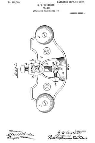
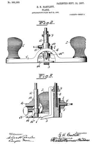
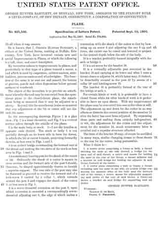
In the accompanying drawings Figure 1 is a plan view; Fig. $2 is a front elevation; and Fig. 3 is a vertical section taken through the middle of the plane.

1 is the main body or stock. 2–2 are the handles at opposite ends thereof. The stock or body 1 is cut partially through on its lower side to form the throat, in which the bit or cutter 3 stands, projecting forwardly therein, as best seen in Figs. 1 and 3.

4 is an arched bridge overstanding the forward end of the throat and uniting the two sides of the stock as best seen in Figs. 1 and 2.

5 is a stationary bearing post for the shank of the cutter or bit. Ordinarily the shank of a cutter is square in cross section and the forward side of the post 5 should, therefore, be shaped approximately thereto to furnish a superior support. The rear side of the post may also be flattened or grooved to receive the forward end of a lock-screw 6 carried by a collar 7, which extends around the post 5 and engages the shank of the cutter 3, as best seen in Fig. 1.

8 is a screw-threaded extension on the post 5, upon which extension is mounted a correspondingly screw-threaded adjusting nut 9, the edge of which makes a connection with the shank of the cutter so that by loosening up on screw 6 and adjusting the nut 9 up and down, the cutter can be raised and lowered to project to the desired depth below the sole of the body.

10 is a bracket preferably formed integrally with the arch or bridge 4.

11 is a set-screw for the bracket 10.

12 is a vertically adjustable post mounted in the bracket 10 and carrying at its lower end what I term a throat-closer or adjuster 14, which latter may, if desired, be detachably secured to the post 12 by means of a collar 14a and binding-screw 15.

The bracket 10 is preferably formed at the rear of the bridge or arch 4.

For certain kinds of work it is preferable to have a closed throat while for other kinds of work it is preferable to have an open throat. With my improvement the plane may be converted into one or the other at will. The adjustment up and down for the cutter in no way affects or disturbs the correct position of the member 14 after the latter has once been adjusted. By separating these parts and making them entirely independent, to wit, the adjustment for the cutter and the adjustment for the member 14, much unnecessary labor is avoided and a superior structure afforded.

The form of the bracket 10 may, of course be modified in many ways, similar clamping means to those shown to the rear for the cutter, being permissible.

What I claim is —

1. A router plane comprising a frame or body, a throat entering the same at one side thereof, a bridge for the open end of said throat, a cutter and means for holding the same at the rear of the throat, a throat adjuster and a bracket on said bridge for holding the adjuster in said throat forward of the cutter.

2. A router plane comprising a body or frame, a throat extending into the same at one side, an arched bridge connecting the opposite sides of the body near the forward end of the throat, a cutter, means for adjustably supporting said cutter at the rear of said throat, a throat-adjuster, a bracket on said bridge for supporting said adjuster.

GEORGE HUNTER BARTLETT.

Witnesses:
NORMAN O. DE BOCK,
FRANK C. FERGUSON.

No. 231,331 – Bench-Plane (Frederic Kraengel) (1880)

[paiddownloads id=”310″]231331


UNITED STATES PATENT OFFICE.

_________________

FREDERIC KRAENGEL, OF BUFFALO, NEW YORK, ASSIGNOR OF ONE-HALF OF HIS RIGHT TO EMIL JETTER AND ALBERT JETTER, OF SAME PLACE.

BENCH-PLANE.

_________________

SPECIFICATION forming part of Letters Patent No. 231,331, dated August 17, 1880.
Application filed April 30, 1880. (No model.)

_________________

To all whom it may concern:

Be it known that I, FREDERIC KRAENGEL, of Buftalo, in the county of Erie and State of New York, have invented certain new and useful Improvements on a Bench-Plane; and I do hereby declare that the following description of my said invention, taken in connection with the accompanying sheet of drawings, forms a full, clear, and exact specification, which will enable others skilled in the art to which it appertains to make and use the same.

This invention has general reference to planes; and it consists in certain peculiar combination of parts and details of construction whereby the plane iron or irons are rendered adjustable, and the throat of the plane-stock enlarged or diminished, substantially in a manner as hereinafter first fully set forth and described, and then pointed out in the claims.

In the drawings already referred to, which serve to illustrate my said invention more fully, Figure 1 is a side elevation of a bench-plane embodying my invention. Fig. 2 is a longitudinal sectional elevation of the same. Fig. 3 is a perspective view of the plane-stock. Fig. 4. is a side elevation of a plane slightly modified. Fig. 5 is an end elevation of the same. Fig. 6 is a perspective view of the carriage, and Fig. 7 a longitudinal sectional elevation of a plane having a single plane-iron and its manner of adjustment slightly modified.

Like parts are designated by corresponding letters of reference in all the figures.

A represents the metallic plane-stock, the sides of which are raised centrally and provided with a bridge, B. In front of this bridge I provide a cross-piece, C, to which is fastened the front handle or knob, D, by means of a screw, E. In the rear of the bridge B, I provide another cross-piece, F, to which is fixed a rearwardly-projecting screw-bolt, G, and in rear of this cross-piece I provide a rise or boss, H, while near the tail of said stock I provide a lug, J.

Within the sides of the stock A, and in rear of the cross-piece F, I place a carriage, I, (shown in detail in Fig. 6,) said carriage consisting of a curved base-plate, I’, having on one end a standard, K, and on the other end a lug, L. In this standard I provide an aperture, a, for the passage of the bolt G, and in the bed-plate J’, close to the standard K, an aperture, b, for the reception of part of a nut, M, engaging said screw G. To the lug L on said carriage is fitted a handle, N.

Within the lug J, on the rear end of the stock A, I swivel a screw-rod, O, extending forwardly through the rise H and cross-piece F into a frame, l’, the forward rail, Q, of which is beveled on its upper surface to correspond somewhat to the inclination ofthe plane-irons R.

The cutting-iron has on its upper end a right-angled bend, R’, provided with a curved notch, d, into which is passed a rod, S, having on its upper end a head, S’, on its opposite end a screw-thread engaging a female thread in near the upper end of the standard K.

These plane-irons are clamped into position by a clamping-plate, T, interposed between the bridge B and said plane-irons, said clamping~plate having a micrometer-screw, U, arranged to press upon said plane-irons.

In the carriage I, I provide a slotted aperture, f, through which is passed a micrometer-screw, V, having its female thread in an aperture, g, in the lug H.

The object of constructing a plane as described is to enable me to vary the inclination of the plane-irons, and also to close or open the throat of the plane-stock by means of said irons, and these results are accomplished in the following manner:

It being desired to close or open the throat of the plane-stock, the irons are first adjusted to the thickness of shaving or cutting required. This is done by turning the head S’ of the screw-rod S in one or the opposite direction. The screw-rod S, having a fixed nut in the standard K and a swiveling connection with the plane-iron in the curved slot-hole d, Fig. 6, works the plane-iron up or down, in accordance with the direction in which it is turned, until the cutting-edge of said iron projects beyond the lower plane surface the desired distance. lf now a wider or narrower throat is wanted I first move the bearing-frame P, Fig. 3, by means of the head J’ on the screw-rod O, and the nut M on the screw-bolt G, both in the proper direction, which will cause the cutting-edge of the plane-iron to move forward or backward, as the case may be. This being accomplished, nothing remains to be done but to insert the wedge T, and then to clamp the irons down upon the standard K and rail Q by the micrometer-screw U, and finally to fix the carriage I in position by the micrometer-screw V.

To alter the inclination of the plane-irons the frame P and carriage I are moved forward or backward, as the case may be, bearing in mind the fact that the irons are, so to speak, fulcrumed upon the rail Q, and that to lower the irons the standard must be moved backward, and that a contrary movement produces a corresponding result.

It will thus be seen that the standard K and frame P form a rest for the plane-irons, and that, as already mentioned, by a forward or backward movement of the same, the size of the throat is enlarged or diminished, while by working the carriage alone the inclination of the irons is altered.

It is perfectly evident that one of the objects in view — viz., the varying of the inclination of the plane-irons — can be carried into effect without the bearing-frame P, and in Fig. 7 I have shown such a device. Here the lower or cutting edge of the plane-iron rests against the plane-stock in the throat instead of the inclined rail Q, heretofore described, while the said iron is carried upon the standard K, the same as in the other device. In this case the inclination of the plane-iron is accomplished by moving the carriage I the same as heretofore described.

By means of this device the size of the throat may also be varied to some extent by altering the inclination of the plane-iron and working the screw-rod S in a manner readily understood.

As hereinbefore described, the plane-iron is adjusted for the depth of cutting by means of the screw-rod S, Figs. 1, 2, and 7, working in the slot-hole d, Figs. 6 and 7. This construction may, however, be varied by fixing the screw-rod S as shown in Fig. 4, and allowing a circular nut, W, to operate upon said screw-rod, and with its faces within a cross-slot in the plane-iron, whereby by moving said nut up or down the screw-rod the iron is moved along in a corresponding direction.

Having thus fully described my invention, I claim as new and desire to secure by Letters Patent of the United States —

1. In bench-planes, a carriage for the bits, consisting, essentially, of the bed~plate I’, having on its forward end a standard, K, provided in its upper part with a screw-threaded aperture for the reception of an inclined screw-rod, S, said carriage having a slot-hole, f, for the passage ofa screw, V, by means of which said carriage is held down to the plane-stock, an aperture, a, in the standard K for the passage of a screw-bolt, G, and a slot-hole, b, in the bed-plate I’ for the reception of a micrometer-nut, M, whereby the said carriage is moved horizontally upon the plane-stock, substantially as and for the use and purpose specified.

2. In planes, a carriage for the plane-bits, having a standard, K, for supporting said bits, at a point about midway of their length, in combination with a bearing-frame for the lower or cutting end of said bits, said carriage and bearing-frame being both horizontally adjustable, as specified, whereby the inclination of the bit and the size of the throat of said plane may be varied simultaneously by moving the carriage and bearing-frame either in the same or in opposite directions, substantially in the manner as and for the object stated.

3. In planes, the device for adjusting the depth of cutting of the plane-iron, consisting, in combination with a fixed nut, of a revolving screw-spindle, S, operating within a slot-hole, d, in the part R’ of said plane-iron, as and for the purpose specified.

4. The combination, with the stock A, having the lug J, bridge B, and cross-piece F, with the screw-rod G, of the screw-rod O, with head J’, carriage I, with standard K, plane-iron R, with screw-rod S, and wedge T, with set-screw U, as stated.

In testimony that I claim the foregoing as my invention I have hereto set my hand in the presence of two subscribing witnesses.

F. KRAENGEL.

Witnesses:
MICHAEL J. STARK,
HATTIE L. WALKER.

No. 124,435 – Improvement In Spoke-Shaves (Jacob Groben) (1872)

[paiddownloads id=”192″]124435


UNITED STATES PATENT OFFICE.

_________________

JACOB GROBEN, OF BUFFALO, NEW YORK, ASSIGNOR TO HIMSELF AND
SAMUEL D. SIKES, OF SAME PLACE.

EMPROVEMENT IN SPOKE-SHAVES.

_________________

Specification forming part of Letters Patent No. 124,435, dated March 12, 1872.

_________________

Specification describing certain Improvements in “Spoke-Shaves,” invented by JACOB GROBEN, of Buffalo, in the county of Erie and State of New York.

Nature of the Invention.

This invention relates to certain improvements in spoke-shaves, and it consists of the combination of certain parts as will hereinafter be set forth.

General Description.

In the drawing, Figure 1 is a back elevation. Fig. 2 is a bottom-plan view. Fig. 3 is a cross-section.

A represents the stock, B the cutter or knife, and C the face-guide. The knife is of a rectangular form, without lugs or ears to hold it; but has, instead, slanting edges, which are chamfered off, and which fit in metal sockets a a’, having slanting-grooves b b’, into which these edges set. These goooves are set slanting toward the front, to prevent the knife from slipping out, but more particularly to allow the knife to be set forward whenever the edge becomes worn or ground down, so that the space between the knife and guide may be kept always at the right adjustment. In order to hold the knife in position after it is set forward, I provide one or both of the sockets a a’ with a slot, c, through which a set-screw passes, by which the sockets can be set a little forward, as may become necessary, to keep the knife in proper place. On the under side of the sockets I form lugs e e, which fasten into the wooden stock by the pressure of the screw. The face-guide C, which graduates the cutting, works up and down in the grooves d d’, formed in the side of the stock A. It is held at any height by means of a single screw, E. By these simple devices the throat can be set at any size, and down to the very smallest space, so that cross-grained stuff can be worked just as well as straight stuff, and prevents the knife “eating ” into the wood.

This device of mine makes a very simple but very durable spoke-shave, only being required that the knife should be renewed occasionally to last a long time. It will adjust to a curved as well as a straight-cutter, and will be excellent for sweep-work.

Claim.

The slotted plates a a’, formed with the lugs e, and inclined grooves b b’, in combination with the knife B, and with the movable face guide-plate C, and its adjusting-screw E, all constructed and operating as set forth.

ln witness whereof I have hereunto signed my name in the presence of two subscribing witnesses.

JACOB GROBEN.

Witnesses:
J. R. DRAKE,
C. N. WOODWARD.

No. 89,369 – Low Angle Bench Plane (Stephen W. Woodward) (1869)

[paiddownloads id=”52″]89369


UNITED STATES PATENT OFFICE.


STEPHEN W. WOODWARD, OF BUFFALO, NEW YORK.

Letters Patent No. 89,369, dated April 27, 1869; antedated April 16, 1869.
_________________

IMPROVEMENTS IN PLANE FOR CARPENTERS’ USE.

_________________

The Schedule referred to in these Letters Patent and making part of the same.

_________________

To all whom it may concern:

Be it known that I, STEPHEN W. WOODWARD, of the city of Buffalo, in the county of Erie, and State of New York, have invented certain new and useful Improvements in Planes for Carpenters’, Joiners’, or Cabinet-Makers’ Use ; and do hereby declare the following to be full, clear, and exact description there-of, reference being had to the accompanying drawings, and to the letters of reference marked thereon.

The nature of my invention consists in the manner of placing the plane-iron with its face downward, holding the cutting-edge of the same firmly in any required position, and elevating or lowering, forcing outward or withdrawing the same, by means of screws and pins.

In order to enable others skilled in the art to make and use my invention, I will now proceed to describe its construction and operation, referring to the annexed drawings, which form a part of this specification, and in which —

Figure 1 is a dissected view of the plane, and
Figure 2 is a sectional view of the same.

Fig. 1 represents a cast-iron plane, with a slot marked a cast in the body of the plane, for the purpose of guiding and holding a screw marked b, the operation of which screw is intended to elevate or depress the cutting-edge of the plane-iron, at the same time opening and closing the throat of the plane, so as to gauge the thickness of the shaving or cut.

C represents a thumb-screw attached to the plane-iron, for the purpose of forcing outward, withdrawing, and at the same time assisting to hold in any required position, the cutting-edge of the plane-iron.

This screw C enters the sleeve I, which is hinged or pivoted in such a manner to the rear end of the plane-bit E, that said end may be adjusted vertically without affecting the screw.

The screw C not being cramped by the movement of the rear end of the plane-bit, is left free to act upon said bit, for giving it an endwise adjustment at any angle it may assume.

d represents the cap, with screw d, holding the plane-iron firmly in its place.

This cap is caught beneath two pins, or lugs J, on the inner faces of the flanges, forming the sides of the plane, and with its screw d, serves to press down and hold in position the forward end of the same bit.

Having thus fully described my invention,
What I claim as new, and desire to secure by Letters Patent, is —

The sleeve I, provided with jaws, and pivoted to the bit E, arranged with the screws C and b, to operate as set forth.

STEPHEN W. WOODWARD.

Witnesses:
J. H. BARTON,
W. C. SHERWOOD.