No. 64,341 – Improvement In Plane-Irons (S. Markee) (1867)

[paiddownloads id=”124″]64341


United States Patent Office.


S. MARKEE, OF AUBURN, NEW YORK, ASSIGNOR TO HIMSELF AND JOHN M. EASTERLEY, OF SAME PLACE.

Letters Patent No. 64,341, dated April 30, 1867.
_________________

IMPROVEMENT IN PLANE-IRONS.

_________________

The Schedule referred to in these Letters Patent and making part of the same.

_________________

TO ALL WHOM IT MAY CONCERN:

Be it known that I, S. MARKEE, of Auburn, in the county of Cayuga, and State of New York, have invented a new and useful Improvement in Plane-Irons; and I do hereby declare that the following is a full, clear, and exact description thereof, which will enable others skilled in the art to make and use the same, reference being had to the accompanying drawings, forming a part of this specification, in which —

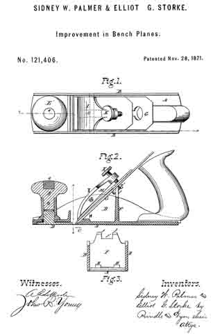
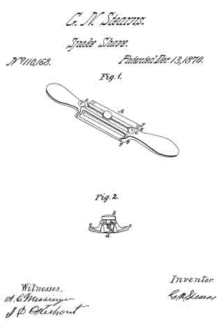
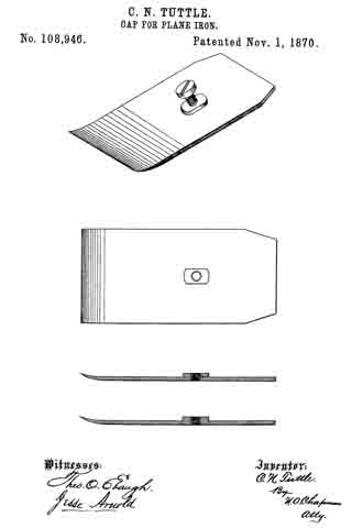
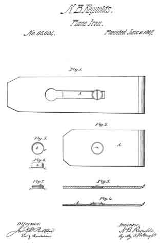
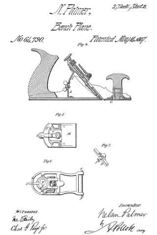
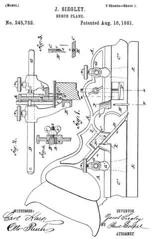
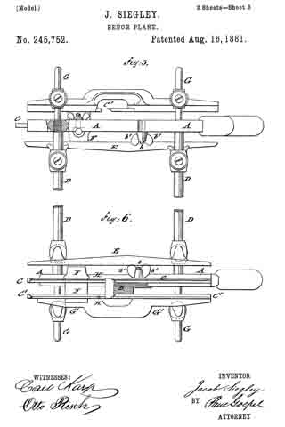
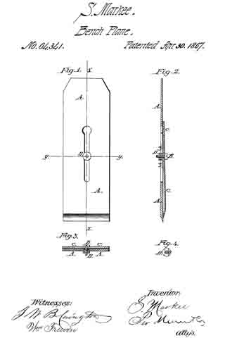
Figure 1 is an under side view of the plane-iron, showing the sliding-nut.

Figure 2 is a longitudinal section of the same, taken through the line x x, fig. 1.

Figure 3 is a cross-section of the same, taken through the line y y, fig. 1.

Figure 4 is a detail sectional view, taken through the line z z, fig. 2, showing the under side of the sliding-nut.

Similar letters of reference indicate like parts.

My invention has for its object to furnish an inaproved double plane-iron, simple and cheap in construction, and convenient in operation; and it consists, first, in attaching the cap to the plane-iron by a screw and sliding-nut; and, second, in the sliding-nut in combination with the plane-iron cap and screw, as hereinafter more fully described.

A is the plane-iron, which has a longitudinal slot, as shown, for the passage of the screw B, which secures the cap C to the plane-iron. The upper end of this slot is enlarged so that the nut D can he passed through it.

The cap C is made of sheet steel, slightly curved in its lower part, as shown in fig. 2. Through this cap is made a hole for the passage of the screw B. The screw B passes through the cap C and through the slot in the plane-iron A, and screws into the sliding-nut D, as shown in fig. 2. This nut is made with a projecting part or flange, as shown in figs. 2, 3, and 4, which its into the slot formed in the plane-iron A, and slides along said slot in adjusting the cap C upon the plane-iron A. By this construction it is not necessary to make the cap C as heavy as it was formerly made, when it had to be made thick enough to receive and hold the screw that held the cap and plane-iron together. This construction enables me to place the head of the screw on the upper side of the plane-irons, making it much more convenient to adjust the cap in proper position with reference to the cutting edge of the plane-iron than when the head of the connecting-screw was on the under side of the plane-iron, as was the case when the cap and plane-iron were connected together in the ordinary manner.

What I claim as new, and desire to secure hy Letters Patent, is —

The plane-iron, consisting of the slotted iron A, curved cap C, flanged sliding-nut D, and screw B, arranged and operating substantially as described for the purpose specified.

The above specification of my invention signed by me this 7th day of March, 1866.

S. MARKEE.

Witnesses:
B. J. IVES,
R. P. STOW.

No. 121,406 – Improvement In Bench-Planes (Sidney W. Palmer And Elliot G. Storke) (1871)

[paiddownloads id=”189″]121406


UNITED STATES PATENT OFFICE.

_________________

SIDNEY W. PALMER AND ELLIOT G. STORKE, OF AUBURN, NEW YORK,
ASSIGNORS TO WILLIAM J. MOSES, OF SAME PLACE.

IMPROVEMENT IN BENCH-PLANES.

_________________

Specification forming part of Letters Patent No. 121,406, dated November 28, 1871.

_________________

To all whom it may concern:

Be it known that we, SIDNEY W. PALMER and ELLIOT G. STORKE, of Auburn, in the county of Cayuga and in the State of New York, have invented certain new and useful Improvements in Bench-Planes; and do hereby declare that the following is a full, clear, and exact description thereof, reference being had to the accompanying drawing making a part of this specification, in which —

Figure 1 is a plan view of our improved plane. Fig. 2 is a vertical longitudinal section of the same on the line x x of Fig. 1, and Fig. 3 is a vertical cross-section on the line z z of Fig. 2.

Letters of like name and kind refer to like parts in each of the figures.

Our invention is an improvement in that class of bench-planes having metallic stocks; and it consists, principally, in the employment upon the lower side of the pivoted cap of a central rib extending the whole length of said cap, substantially as and for the purposes hereinafter shown. It consists, further, in a cap pivoted at or near its center transversely to the stock, substantially as and for the purpose hereinafter set forth. It consists, further, in the construction of the bearings upon which the heel of the bit rests, substantially as and for the purpose hereinafter specified. It consists, further, in the relative arrangement of the bearings for the heel of the bit with those employed for the body of the same, substantially as hereinafter shown and described. It consists, finally, in the combination of the above-named bearings with the center pivoted cap, substantially as and for the purpose hereinafter set forth.

In the annexed drawing, A represents the name or stock, provided at either side with an upward-projecting flange, B, for inclosing and supporting the cap, and having near its forward end a suitable transverse opening, C, ibr the reception ef the lower or cutting end of the bit, which opening is made variable in width by means of a plate, D, that corresponds in width to the length thereof, and sliding longitudinally within a recess formed in the face of the stock, is secured in position, when adjusted, by means of a screw which projects upward through a longitudinal slot within said stock, and is provided upon its upper end with a nut, E. Secured within or upon the upper end of the nut E is a wooden knob, E’, within which is in turn secured a metallic stud or start-pin, e, the upper end of which is considerably enlarged so as to enable it to resist a blow from a hammer when it is desired to start back the bit. Projecting vertically upward from the stock A, near its longitudinal center, is a diaphragm, F, which from the upper edges of the flanges B curves inward and upward and terminates in two lugs, f separated by means of a notch, f’, upon which, when in position, the body of the bit G rests. The notch f’ is deepened sufficiently to permit of the passage of the screw g’ of the cap G’, by which means less space vertically is required for the removal of the bit than would otherwise be the case. At a short distance in rear of the opening C are placed two other lugs, H, which correspond in width and relative transverse position with those above described, and furnish a bearing for the heel of the bit. It will be readily seen that being supported at but two points midway between its transverse center and edges the bit must invariably have a firm bearing, however unequal its thickness or uneven its heel. Pivoted to and within the upper edges of the flanges B is a cap, I, having the usual curved form and provided at and through its upper and rear end with a suitable set-screw, K. Instead of the usual transverse rib for the reception of the pivot-rod L, a longitudinal rib, M, extends through the center of the cap, and not only contains said rod, but also strengthens said cap and enables other portions ofthe same to be made much lighter than would otherwise be practicable.

By making the opening through the rib M for the passage of the pivotal rod L slightly larger than said rod the cap will be enabled to adjust itself vertically to the bit, however unequal in thickness the same may be at its lower end. Another advantage possessed by the longitudinal rib is that it not only offers no obstruction to the center of the bit, but rather furnishes a guide for the same, while in caps where the transverse rib is employed great care is required in inserting the bit to avoid hitting said rib with the same and injuring its cutting-edge.

Having thus fully set forth the nature and merits of our invention, what we claim as new is —

1. In metallic bench or other planes a pivoted cap, provided upon its lower side with a central longitudinal rib, substantially as and for the purpose specified.

2. The cap I, pivoted loosely at or near its transverse center, substantially as and for the purpose shown.

3. The arrangement of the lugs or bearings H upon the stock A, substantially as shown and for the purpose described.

4. The stock A, provided with the bearings H and f arranged substantially as and for the purpose set forth.

5. In combination with the bearings H and f and a suitable bit, the cap I, pivoted at or near its transverse center, substantially as and for the purposes specified.

In testimony that we claim the foregoing we have hereunto set our hands this 10th day of August, 1871.

ELLIOT G. STORKE.
SIDNEY W. PALMER.

Witnesses:
HORACE T. COOK,
JAY E. STORKE.

No. 114,085 – Improvement In Plane-Irons (Ira Almy And Sereno A. Drake) (1871)

[paiddownloads id=”184″]114085


United States Patent Office.


IRA ALMY AND SERENO A. DRAKE, OF COVERT, NEW YORK.

Letters Patent No. 114,085, dated April 25, 1871.
_________________

IMPROVEMENT IN PLANE-lRONS.

_________________

The Schedule referred to in these Letters Patent and making part of the same.

_________________

To all whom it may concern:

Be it known that we, IRA ALMY and SERENO A. DRAKE, both of Covert, Seneca county, State of New York, have invented certain new and useful Improvements in Plane-Iron, of which the following is a full, clear, and exact description, reference being had to the accompanying drawing making part of this specification, in which —

Figure 1 is a view of our improved plane-iron with the parts arranged in a proper working relation to each other, and Figure 2 is a detached view of the lower iron or bit with the cap removed.

Similar letters of reference denote corresponding parts in both figures.

The invention relates to the construction of double irons — that is, those composed of two parts — to wit: a lower or cutting~blade or bit, and an upper part or cap, this cap being attached to the bit by means of a screw.

These double irons are usually employed in jointing-planes and srnoothing-planes, when smooth and accurate work is required.

The invention consists in making the bit reversible, having both ends constructed with a cutting-edge, in combination with a cap having a longitudinal slot therein, as will be hereinafter fully explained.

In the drawing —

A represents the cap, made, preferably, of wrought or malleable iron, and substantially in the form of an ordinary single plane-iron, except that, when in proper position in the plane-stock, the bevel at the lower end is upon the upper side instead of on the lower side, as it is in a plane-iron.

This cap is provided with a long narrow slot, enlarged into a circular form at the upper end, to admit the passage of a screw, which will soon be described.

B is the bit or cutting-blade, made in the form shown plainly in fig. 2. Both ends of this bit are made in the same shape, so that they can be used for cutting-edges, and, in practice, we deem it advisable to make it entirely of steel.

C is a set-screw, the shank of which is adapted to engage with a thread cut in the central portion of the bit, as at b, fig. 2.

By preference we provide the bit with a rectangular rib, B’, of such a width as will allow it to slip into the slot c, and of a height a little less than the thickness of cap A.

The object of this rib B’ is to assist in maintaining the bit and cap in a proper relation to each other when they are connected by means of the screw, as in fig. 1, and more particularly for the purpose of adjusting the parallelism of the cutting-edge and the bottom or working face of the plane-stock; but, as this rib may not in all eases be found to he essential, we do not wish to be limited to its use.

The construction and operation of the device is so simple that a more detailed description is not deemed necessary.

Having now described the invention, What we claim as new, and desire to secure by Letters Patent, is —

The herein-described plane-iron, consisting of the cap A and the reversible bit B, substantially as shown and described.

IRA ALMY.
SERENO A. DRAKE.

Witnesses:
JAMES C. KNIGHT,
O. G. WHEELER.

No. 119,133 – Improvement In Carpenters’ Planes (Henry N. Frederick) (1871)

[paiddownloads id=”187″]119133


UNITED STATES PATENT OFFICE.

_________________

HENRY N. FREDERICK, OF HANCOCK, NEW YORK.

IMPROVEMENT IN CARPENTERS’ PLANES.

_________________

Specification forming part of Letters Patent No. 119,133, dated September 19, 1871.

_________________

To all whom it may concern:

Be it known that I, HENRY N. FREDERICK, of Hancock, in the county of Delaware and State of New York, have invented a new and Improved Carpenters’ Plane; and I do hereby declare that the following is a full, clear, and exact description thereof, which will enable others skilled in the art to make and use the same, reference being had to the accompanying drawing forming part of this specification.

Figure 1 represents a side view, partly in section, of my improved carpenters’ plane. Fig. 2 is a vertical transverse section of the same taken on the plane of the line c c, Fig. 1.

Similar letters of reference indicate corresponding parts.

My invention consists in the improvement of carpenters’ planes, as hereinafter described and subsequently pointed out in the claim.

A, in the drawing, represents the block or frame of a carpenter’s plane. B is the planing-iron. The face of the iron has a toothed portion, a, into which mesh the teeth of a segment, C. This segment is formed at the lower end of a lever, D, that turns on a pin, b, whose bearings are in the sides of the plane. By swinging the lever D on its pivot, the iron B will be set up or down, as may be desired. E is a slotted lever pivoted to the plane A. By means of a thumb-screw, d, fitting through the lever E into D, the latter can be clamped to lock the iron B in any suitable position. Other means for thus securing the lever D and iron, may, however, be substituted for lever E and screw d.

Having thus described my invention, I claim as new, and desire to secure by Letters Patent —

The toothed segment C pivoted to the plane A, and combined with the iron B, which has the toothed portion a, substantially as herein shown and described.

HENRY N. FREDERICK.

Witnesses:
M. D. WHEELER,
MILO SCUTT.

No. 124,435 – Improvement In Spoke-Shaves (Jacob Groben) (1872)

[paiddownloads id=”192″]124435


UNITED STATES PATENT OFFICE.

_________________

JACOB GROBEN, OF BUFFALO, NEW YORK, ASSIGNOR TO HIMSELF AND
SAMUEL D. SIKES, OF SAME PLACE.

EMPROVEMENT IN SPOKE-SHAVES.

_________________

Specification forming part of Letters Patent No. 124,435, dated March 12, 1872.

_________________

Specification describing certain Improvements in “Spoke-Shaves,” invented by JACOB GROBEN, of Buffalo, in the county of Erie and State of New York.

Nature of the Invention.

This invention relates to certain improvements in spoke-shaves, and it consists of the combination of certain parts as will hereinafter be set forth.

General Description.

In the drawing, Figure 1 is a back elevation. Fig. 2 is a bottom-plan view. Fig. 3 is a cross-section.

A represents the stock, B the cutter or knife, and C the face-guide. The knife is of a rectangular form, without lugs or ears to hold it; but has, instead, slanting edges, which are chamfered off, and which fit in metal sockets a a’, having slanting-grooves b b’, into which these edges set. These goooves are set slanting toward the front, to prevent the knife from slipping out, but more particularly to allow the knife to be set forward whenever the edge becomes worn or ground down, so that the space between the knife and guide may be kept always at the right adjustment. In order to hold the knife in position after it is set forward, I provide one or both of the sockets a a’ with a slot, c, through which a set-screw passes, by which the sockets can be set a little forward, as may become necessary, to keep the knife in proper place. On the under side of the sockets I form lugs e e, which fasten into the wooden stock by the pressure of the screw. The face-guide C, which graduates the cutting, works up and down in the grooves d d’, formed in the side of the stock A. It is held at any height by means of a single screw, E. By these simple devices the throat can be set at any size, and down to the very smallest space, so that cross-grained stuff can be worked just as well as straight stuff, and prevents the knife “eating ” into the wood.

This device of mine makes a very simple but very durable spoke-shave, only being required that the knife should be renewed occasionally to last a long time. It will adjust to a curved as well as a straight-cutter, and will be excellent for sweep-work.

Claim.

The slotted plates a a’, formed with the lugs e, and inclined grooves b b’, in combination with the knife B, and with the movable face guide-plate C, and its adjusting-screw E, all constructed and operating as set forth.

ln witness whereof I have hereunto signed my name in the presence of two subscribing witnesses.

JACOB GROBEN.

Witnesses:
J. R. DRAKE,
C. N. WOODWARD.

No. 110,168 – Improvement In Spoke-Shaves (George N. Stearns) (1870)

[paiddownloads id=”176″]110168


United States Patent Office.


GEORGE N. STEARNS, OF SYRACUSE, NEW YORK.

Letters Patent No. 110,168, dated December 13, 1870.
_________________

IMPROVEMENT IN SPOKE-SHAVES.

_________________

The Schedule referred to in these Letters Patent and making part of the same.

_________________

To all whom it may concern:

Be it known that I, GEORGE N. STEARNS, of the city of Syracuse, in the county of Onondaga and State of New York, have invented a new and improved Mode of Spoke-Shave; and I do hereby declare that the following is a full, clear, and exact description thereof, reference being had to the accompanying drawings and to the letters of reference marked thereon making a part of this specification, in which —

Figure 1 is a perspective view of the same.
Figure 2 is a sectional view, showing the gauge, one on each side of the knife, and the adjusting-screw inserted in the stock.

This invention relates to a new adjusting spoke-shave.

One object of my invention is in adjusting both sides of the gauge iron; the arms at the same time, thereby presenting a true and even cut the entire length of the knife.

To enable others skilled in the art to make and use my invention, I will proceed to describe its construction and operation.

In the accompanying drawings —

A represents the stock, which may be made any suitable shape or size, and of wood or metal. I prefer to make it in the shape shown in the drawing A, and of metal.

b represents the screw, inserted in the stock A for the adjusting of the gauge e e to and from the knife d.

The gauge e e is fastened to the stock A by the means of two bolts F F at the end of the arms g g.

The knife d is fastened to the stock A by the means of two screws C C, the knife d being stationary.

I am aware that other spoke-shaves have been constructed before my invention in which adjusting-gauges have been used in conjunction with knives, but such gauges and substances were differently arranged from mine, and are liable to many serious objections, which are removed by my arrangernents.

Therefore, I do not claim, broadly, the adjusting-gauge when arranged upon a different principle from that involved by my arrangements.

Having thus described my invention,

What I claim as new, and desire to secure by Letters Patent, is —

The spoke-shave herein described, consisting of stock A, gaugee e, constructed, arranged, and operating substantially as described.

GEO. N. STEARNS.

Witnesses:
A. C. MESSENGER,
HARRY GIFFORD.

No. 109,174 – Improvement In Planes (Lewis Bundy) (1870)

[paiddownloads id=”175″]109174


United States Patent Office.


LEWIS BUNDY, OF MOOER’S FORKS, NEW YORK.

Letters Patent No. 109,174, dated November 15, 1870.
_________________

IMPROVEMENT IN PLANES.

_________________

The Schedule referred to in these Letters Patent and making part of the same.

_________________

To all whom it may concern:

Be it known that I, LEWIS BUNDY, of Mooer’s Forks, in the county of Clinton and State of New York, have invented a new and useful Improvement in Combination Match-Plane and Plow; and I do hereby declare that the following is a full, clear, and exact description thereof; which will enable others skilled in the art to make and use the same, reference being had to the accompanying drawing forming part of this specification.

This invention relates to a new and useful improvement in a combined match-plane and plow, for working in wood, whereby tongues and grooves of variable depth and of variable width of margin may be cut; and

It consists in connecting with a plane-stock two adjustable rabbet-planes and an adjustable grooving-tool or plow, arranged to operate as hereinafter more fully described.

In the accompanying drawing —

Figure 1 represents a top or plan view of the cornbined tools.
Figure 2 is a view of the rabbeting side of the tool, and showing the gauge on the stock.
Figure 3 is a view of the opposite side, showing the grooving-tool or plow.
Figure 4 is a cross-section of fig. 1, taken on the line x x.

Similar letters ot reference indicate corresponding parts.

A is a central stock, with a handle, B, at each end, the cutting-tools connected therewith being arranged on both sides, so that the stock has to be reversed for cutting a tongue and a groove.

C and D are bars which pass transversely through the stock, (to which they are rigidly attached,) and stand at right angles therewith.

The ends of these bars extend out from either side of the stock, as seen in fig. 1, and the grooving and rabbeting-planes are mortised so as to receive the bars, and are made adjustable thereon, or made to slide to or from the sides of the stock, and are held in any desired position by means of set-screws, marked E.

F and G are two rabbet-planes, which are thus placed upon one side of the stock, and which are adjustable on the bars independently of each other, so as to adapt those planes (or either of them) to other uses than simply cutting tongues for the grooving-plane or plow on the other side of the stock.

H is the plow, which is adjustable to or from the stock, the same as the rabbet-planes.

I is the metallic plate which supports the plow-iron J, and enters the groove as it is cut, as is common with grooving-plows.

K is the gauge on the side of the stock for governing the margin or the distance from the side or angle of the lumber to the groove.

L represents the opposite side of the stock or gauge for the rabbet-planes.

N represents adjustable gauges for governing the depth of cut of the rabbet-planes and the plow.

The inside rabbet-plane F is made to discharge its shaving inward toward the stock, the latter being recessed out, so as to allow of a free discharge.

For tonguing and grooving lumber of varying thicknesses, and for various other purposes in house-joining and other kinds of wood-work, this combined tool will be found ofthe greatest advantage.

Having thus described my invention, I claim as new and desire to secure by Letters Patent —

The plane-stock A, in combination with the bar G, plow H, and rabbet»planes F G, constructed and operating as and for the purpose described.

LEWIS BUNDY.

Witnesses:
CHARLES GALE,
CLINTON P. SHELDON.

No. 108,946 – Improvement In Caps For Plane-Irons (Charles N. Tuttle) (1870)

[paiddownloads id=”173″]108946


United States Patent Office.


CHARLES N. TUTTLE, OF AUBURN, NEW YORK.

Letters Patent No. 108,946, dated November 1. 1870.
_________________

IMPROVEMENT IN CAPS FOR PLANE-IRONS.

_________________

The Schedule referred to in these Letters Patent and making part of the same.

_________________

I, CHARLES N. TUTTLE, of Auburn, Cayuga county, New York, have invented certain new and useful Improvements in Caps for Plane-Irons, of which the following is a specification.

Heretofore, in the manufacture of steel caps for plane-irons, it has been usual to forrn the raised hub that enters the elongated-slot of the cutter-iron, and that receives the confining and adjusting-screw, from the body of the cap itself, by swaging up such hub; but this is quite an expensive process, and necessitates the heating to a greater degree, and for a longer time, of the cap.

My object is to cheapen the construction of the cap and manufacture it by a simpler process; and

My invention consists in a cap having a metallic hub secured thereto by brazing, and which is afterward provided with a screw-thread, and thus forms an improved cap.

In the accompanying drawing —

Figure 1 represents, in perspective, my improved cap;
Figure 2, a. top view;
Figure 3, longitudinal central section; and
Figure 4, a longitudinal central section of a modified form.

A represents the cap of a double plane-iron, which is to be formed of steel; but, instead of swaging up a hub on the surface of the cap, I am enabled to do entirely away with such action by simply cutting off from a strip of smooth iron of proper width and thickness a length suitable for a hub, B, and this I secure to the surtitce of the cap, which I am enabled to make irom the regular rolled steel or iron, by means of brazing.

It will be evident to those skilled in the manufacture of these articles that it is a great desideratum to be able to use the regular rolled steel or iron, and have simply to cut it off the proper length, turn the corners, and round up and sharpen the Iower edge, thus obviating the heating and working of but one end.

The cap and hub are provided with a hole either after or before brazing the hub to the cap, which is provided with a thread to receive a confining and adjusting-nut, C’, which I prefer to make of malleable iron on account of cheapness and durability.

Instead of brazing the hub directly to the surface of the cap, I may punch a hole of suitable size through the cap, and in this hole place a hub of at thickness necessary to fill up such opening, and also project the proper distance above the cap to form a hub, as in fig. 4, and this hub I brazed in or to the opening in the cap.

In all cases where a hub is formed or secured to the cap by swaging, the hub has afterward to be dressed square on the sides; but with a hub previously squared in its manufacture, and then brazed, this tedious and rather expensive portion of the manufacture is avoided.

Having described my invention, I claim —

The plane-iron cap, provided with a nut when each is formed in separate pieces, and brazed together, as and for the purpose herein specified.

C. N. TUTTLE.

Witnesses:
C. W. UPHAM,
C. N. TUTTLE, Jr.

No. 96,258 – Improvement In Carpenters’ Planes (Georg Müller) (1869)

[paiddownloads id=”154″]96258


UNITED STATES PATENT OFFICE.

_________________

GEORG MÜLLER, OF NEW YORK, N. Y., ASSIGNOR TO HIMSELF AND FRANCIS BURNET, OF SAME PLACE.

IMPROVEMENT IN CARPENTERS’ PLANES.

_________________

Specification forming part of Letters Patent No. 96,258, dated October 26, 1869.

_________________

To all whom it may concern:

Be it known that I, GEORG MÜLLER, of the city, county, and State of New York, have invented a new and useful Improvement in Carpenters’ Planes; and I do hereby declare that the following is a full and exact description of the construction and operation of the same, reference being had to the accompanying drawings, making part of this specification, in which —

Figure 1 is a top view ofi a carpenter’s plane containing my invention; Fig. 2, a side elevation, and Fig. 3 a vertical section, of same. Fig. 4 is an under side view of the retaining-box in connection with the sliding cap-iron; Fig. 5, an inner view of retaining-box with cap-iron removed; Fig. 6, a plan of the sliding cap-iron, and Fig. 7 a longitudinal section of said iron.

This invention relates to a novel device for adjusting the cap and bit-irons of a carpenter’s plane in relation to each other and to the plane, and holding the same firmly in position by means of a swinging box or frame, which is pivoted to the plane-stock, and on which the cap-iron slides, the said box having set-screws for adjusting, retaining, and bracing the box, cap-iron, bit-iron, and plane-stock together, and at the same time rendering the cutting-irons capable ofthe nicest adjustment and stability in relation to each other and to the face of the plane-stock.

Having described the nature of my invention, I will now describe its construction and mode of operation.

In the drawings, A is the plane-stock, B the handle, and C the plane-iron or cutting-bit. D is the cap-iron, having projections e e, which slide on the ways of the box, and having, also, a lip or projection, f, at right angles to its face, in which set-screws (which pass through the end of the box marked g g g’) operate, for purposes hereinafter explained. H is the retaining-box, which receives the cap-iron D, and has ways i i, on which the projections e e of the cap-iron slide, while the projection or lip f of said cap-iron slides on the interior of the box, Fig. 4. This box H is pivoted to the plane-stock at k, and has a clamping-screw, m, for the purpose of bracing the cap and bit irons together, and against the rear, a, of the throat of the plane-stock.

To arrange my plane for operation, I place the bit C in the throat a of the plane-stock. I next set the cap-iron D within the box H and insert the adjusting and clamp screws in their places, and I place the box so equipped in the throat of the plane. I now pass the pivot k through the throat of the plane, and through the box H; and for adjustment of the cap-iron in relation to the bit-iron in a longitudinal or transverse direction I simply turn the screws g g, or either of them, (as the case may be,) back or forth, and when so adjusted hold the cap-iron D in position by the screw g’, abutting against the lip f of the cap-iron, and I next clamp the whole together by means of the screw m, when my improved plane is ready for operation.

It will be seen from the above that by means of the pivot k and clamping-screw m the box H, cap-iron D, and bit-iron C are braced firmly together and against the plane-stock, equally distributing the pressure over the surface of the part a of the throat of the plane: Furthermore, by this arrangement the box H closely tits the throat of the plane laterally, the movements of the cap-iron being pertormed within the box; besides, the box can be brought near the mouth of the plane, thereby giving strength and stability to the cutting-irons, and at the same time easy exit to the shavings, for the reason that I dispense with the prize fork or carrier F, used in the subject of a patent granted me on the 29th day of May, A. D. 1866, and on which I consider my present invention an improvement, inasmuch as the swell on the box E, for reception of the prize-fork, prevented the approach of the box toward the mouth of the plane or end of the cutting-irons, rendering the said irons partially unstable, while it also prevented the easy exit of the shavings, or rather tended to choke the throat of the plane; and, besides this, the said box E was slotted for reception of the joint-pin G, and did not fill the throat of the plane laterally, as provision had to be made for the lateral movements of the cap-iron, and both the box and prize-fork were slid together, while in my present improvement the box H is stationary, while the cap-iron D slides transversely and longitudinally on the ways of the box; and thus I produce an improvement on my former plane, which can be manufactured for two-thirds of its cost.

What I claim as my invention, and desire to secure by Letters Patents, is —

The arrangement of the stationary box H, pivoted to the plane-stock, and fitting closely the the throat thereof laterally, in combination with the cap-iron D, which is moved and adjusted beneath the said box, substantially as and for the purpose herein specified.

In testimony whereof I have hereunto set my signature this 21st day of August, A. D 1867.

GEORG MÜLLER

Witnesses:
FRANZ BERNET;
A. NEILL.

No. 96,052 – Improvement In Plane (E.G. Storke) (1869)

[paiddownloads id=”153″]96052


United States Patent Office.


E. G. STORKE, OF AUBURN, NEW YORK.

Letters Patent No. 96,052, dated October 19, 1869.
_________________

IMPROVEMENT IN PLANE.

_________________

The Schedule referred to in these Letters Patent and making part of the same.

_________________

To all whom it may concern:

Be it known that I, E. G. STORKE, of Auburn, in the county of Cayuga, and State of New York, have invented a new and useful Method of Preventing the Adhesion to the Wood, of the Faces of Metallic Planes; and I do hereby declare that the following is a full, clear, and exact description of the same, reference being had to the annexed drawing, marked “A,” making part of this specification, in which is represented the face of a metallic plane, fluted, grooved, or channelled, according to the plan of my invention.

Those flutes, grooves, or channels, may be more or less in number, and cut to a greater or less depth, provided the object be thereby attained of relieving all extra and unnecessary friction.

The object, however, is fully attained by making them about one thirty-second of an inch deep, one sixteenth of an inch broad, and one eighth of an inch asunder.

Fully one-half of the bearing-surface of the face of the plane may be thus removed, and thus to that extent diminish the points of contact, and the consequent friction, and, at the same time, preserve the full perfection of the working-face of the plane, including its throat.

It has long been known to mechanics that metallic planes have adhered to the wood much closer than wooden planes, and therefore required much more power to operate them.

This excessive friction was caused by their exact and even faces, which were not materially varied by use or atmospheric changes.

When used on very level surfaces, there were so many points of contact that the friction was troublesome, and the adhesion was further increased by atmospheric pressure, as partial vacuums would thus be formed.

The practical effect of this has been to prevent, in a large degree, the introduction and general use of metallic planes.

The object of my invention is twofold, namely, to remove about one-half of the surface of the face of the plane, so that there shall be fewer points of contact, and to form free air-channels, so that no vacuums can be formed, or any trouble arise from atmospheric pressure, however perfect the plane or true the surface on which it is moved.

I effect these two objects by fluting, grooving, or channelling the faces of metallic bench or other planes for wood-workers, as above specified, parallel to their length, or in some equivalent way.

What I claim as my invention, and desire to secure by Letters Patent, is —

A metallic plane, having the face grooved in lines parallel to the sides, in the manner and for the purpose specified.

E. G. STORKE.

Witnesses:
U. L. STORKE,
T. B. BARBER.

No. 97,833 – Improvement In Tool For Cabinet-Makers (Richard W. Tanner) (1869)

[paiddownloads id=”158″]97833


United States Patent Office.


RICHARD W. TANNER, OF ALBANY, NEW YORK, ASSIGNOR TO HIMSELF
AND SAMUEL J. DAVENPORT, OF SAME PLACE.

Letters Patent No. 97,833, dated November 14, 1869; antedated December 11, 1869.
_________________

IMPROVEMENT IN TOOL FOR CABINET-MAKERS.

_________________

The Schedule referred to in these Letters Patent and making part of the same.

_________________

To all whom it may concern:

Be it known that I, RICHARD W. TANNER, of the city and county of Albany, State of New York, have invented a new and useful Tool for Cabinet-Makers, and other workers of veneer; and I do hereby declare that the following is a full, clear, and exact description thereof, reference being had to the accompanying drawings, making a part of this specification, in which —

Figure 1 represents a perspective view of the invention.
Figure 2 is a vertical view of the same.
Figure 3 is a longitudinal section, through red line, in fig.2.
Figure 4 is a cross-section.
Figure 5 is a view of a modification of the form of the face-block.
Figures 6 and 7 are modifications, shown by end sections, of the said face-block.
Figure 8 represents the face-block with a plane-iron suited to this tool.

The nature of my invention consists in a tool-holder and a face-block properly secured together, and so arranged as to receive and hold a scraper or tooth-plane iron, or a straight plane-iron, or any other similar edge tool, by which the workmen plane, tooth, or scrape even the surface of the veneer.

There are many kinds of woods difficult to even on account of the waving or curling nature of the grain of the fibre. By this tool, any and all kinds of wood veneer may be evened and smoothed, with less labor and trouble, than with the hand-held tools now used.

The tool-holder may he constructed of wood or metal, and consists of a bar about a foot long, fur-
nished with a handle on each end, and is furnished with a holding-bar, pivoted to two eye-bolts, furnished with screws and set-nuts, also with a set-bolt, all of which are arranged and connected with the handled har, so as to fix and hold the scraper, plane-iron, or other similar tool, in any required position.

The face-block is secured to the said tool-holder by proper bolts or screws, and is provided with a mouth to permit the passage of the shavings from the wood, as it is being cut from off its surface.

To enable others skilled in the art to make and use my invention, I will proceed to describe it in reference to the drawings, and the letters of reference marked thereon, the same letters indicating similar parts.

One part of my invention consists in the tool-holder, constructed of the double-handled bar A, figs. 1, 2, and 3, and the tool-bar a, pivoted at each end, as shown in fig. 4, to the two eye-bolts e e, figs. 1 and 2.

The said eye-bolts e e pass through the handle-bar A, from the front to the rear, and are provided with thumb-nuts, by which the said tool-bar may be drawn nearer to the handled bar or further from it.

A screw-bolt, c, also works irorn the back ofthe handled bar A, and into it, and through to the tool-bar a, as shown in figs. 1, 2, and 3.

The scraper S, figs. 1 and 2, or plane-iron S’, fig. 8, is placed against the back of the tool-bar a, fig. 3, and between the handled bar A and the said tool-bar, and when thus placed, the said tool S or S’ is secured in its place, at any angle desired, by means of the said set-bolt c and eye-bolts e e.

The other part of my invention consists in the face-block B, shown in iigs. 1, 2. and 3.

The said face-block may be made of wood or metal, and is furnished with a mouth, b, the same as a plane, and may be either straight on its lower face, as in fig. 3, or concave, as in fig. 5, or the reverse, to fit the surface the tool is intended to operate upon, or they may be made either straight, or concave, or convex, longitudinally, as referred to, with moulding forms similar to those shown in figs. 6 and 7, or any other form, as may be required.

The said face-block is secured to the double-handled bar A., figs. 1, 2, and 3, by means of the screws o o, or their equivalents.

A plain flat face-block may be used, as shown in figs. 1 and 3, to which supplementary blocks B’ may be secured, as shown in figs. 5, 6, and 7, and when thus furnished in sets, together with the straps or plane-irons to correspond, the workman will have a tool which will enable him to perform and finish his work with greater ease and facility than can be done with the means they now have.

When a plane-iron, S’, is to be used, as in fig. 8, I would prefer to have the cutting-edge curved forward, as shown.

Having described my invention, What I claim, and desire to secure by Letters Pat~
ent, is —

The tool~holder, consisting of the block B, double-handled bar A, tool-bar a, eye-bolts e e, with their thumb-nuts, and the screw-bolt c, all arranged and constructed to operate as described, substantially as and for the purpose specified.

RICHARD W. TANNER.

Witnesses:
ALEX. SELKIRK,
J. A. BUCKBEE, Jr.

No. 60,265 – Improvement In Mitre Planes (John Sawyer) (1866)

[paiddownloads id=”121″]60265


United States Patent Office.


IMPROVEMENT IN MITRE PLANES.
_________________

JOHN SAWYER, OF MORAVIA, NEW YORK.

Letters Patent No. 60,265, dated December 4, 1866.

_________________

SPECIFICATION.

TO ALL WHOM IT MAY CONCERN:

Be it known that I, JOHN SAWYER, of Moravia, in the county of Cayuga, and State of New York, have invented a new and useful Improvement in Plane; and I do hereby declare that the following is a full, clear, and exact description thereof, which will enable others skilled in the art to make and use the same, reference being had to the accompanying drawings, forming part of this speciication, in which —

Figure 1 is a top view of my improved plane and guide-plate, part being broken away to show the construction.

Figure 2 is an end view of the same.

Similar letters of reference indicate like parts.

My invention has for its object to furnish an improved apparatus by means of which the ends of mouldings may be out at any desired bevel so as to make a close joint; and it consists, first, in the plane, constructed and arranged as hereinafter more fully described; and, second, in the adjustable guide-plate, in combination with the plane, said guide-plate being constructed and arranged as hereinafter more fully described.

A is the plane, which is furnished with two plane-irons, a1 and a2, placed, one in each end of the plane and inclined in opposite directions, as shown in fig. 1. The cutting edges of these plane-irons, a1 and a2, project at the side of the plane, instead of projecting at the bottom, in the usual manner. The plane-irons a1 and a2 are set in grooves in the body of the plane, and are secured in place by wooden wedges, a3 and a4, in the ordinary way, a space being formed in front of said irons and wedges for the escape of the shavings. The handle, a5, is attached to the central part of the upper side, as shown in fig. 1, and should be of such a form that the plane may be conveniently worked in either direction. B is the guide-plate, in connection with which the plane is used. The face of the plate B is grooved longitudinally near one edge, with a shallow groove of such a size that the lower face or side of the plane, A, may accurately fit into it, as shown in fig. 2, so that it may move in a direct line when operated. The depth of this groove should be such that the upper surface of the plate B may be in a line with the lower corner of the plane-irons, as shown in ig. 2. C are the guide-bars, against which the mouldings are held while being operated upon. These guide-bars, C, are pivoted at their inner ends to the plate B, and they are clamped at any angle to give any desired bevel to the ends ofthe moulding by the screws D and thumb-nuts E. The screws D pass through slots formed in the plate B, their heads fitting into a channel formed on the under side of said plate.

I claim as new, and desire to secure by Letters Patent —

The grooved and slotted plate B and pivoted guide-bars C, when used in combination with the plane A, having its iron, a1 a2, inclined in opposite directions, substantially as described for the purpose specified.

JOHN SAWYER.

Witnesses:
E. E. BROWN,
O. R. VAN ETTEN.

No. 64,001 – Improvement In Plane Irons (William H. Eckert) (1867)

[paiddownloads id=”123″]64001


United States Patent Office.


WILLIAM H. ECKERT, OF SYRACUSE, NEW YORK.

Letters Patent No. 64,001, dated April 23, 1867.
_________________

IMPROVEMENT IN PLANE IRONS.

_________________

The Schedule referred to in these Letters Patent and making part of the same.

_________________

TO ALL WHOM IT MAY CONCERN:

Be it known that I, WILLIAM HENRY ECKERT, of the city of Syracuse, Onondaga county, New York, have invented a new and improved Plane; and I do hereby deciare that the following is a full, clear, and exact description of the same, reference being had to the annexed drawings, making a part of this specification.

The letters used represent corresponding parts wherever they occur.

To enable others skilled in the art to make and use my invention, I will proceed to describe the same, and its form when complete and ready for use.

Figure 1 represents a perspective view of the plane irons when put together.

Figure 2 represents the cap.

Figure 3 represents a cross sectional view of both the plane irons, with the nut and screw.

In the common form of plane irons the screw is made to pass directly into the cap, for the purpose of holding the two irons together. This form of construction involves the necessity of unscrewing the cap when-ever the irons are separated for sharpening, or any other purpose of separation. The object of my invention is to dispense with this necessity and enable the irons to separate by simple handling.

I make the cutting iron A in all respects in the common form, with an elongated slot, a, for the movement of the screw s, and with a circular aperture, o, for the screw-head to pass through. Instead of inserting the screw in the cap, I make the nut n, which may be in any convenient form, square, oblong, circular, or other-wise; but I consider the oblong form the best, because best calculated to bold the cap straight with the cutting iron. In the cap C I make the slot or opening h, into which the nut n is made to fit, and it should be so made as to receive the nut with a snug joint. By this means the cap C, which in other respects is made in the common form, is readily adjusted by means of the screw and the irons, separated by slipping the cap C off from the nut n.

What I claim as my invention, and desire to secure by Letters Patent, is —

The nut n, in combination with the planing iron A, the screw s, and the cap C, made and operated substantially as and for the purposes described.

I also claim the slot h in the cap C, when made to it upon the nut n, and applied to planing irons, substantially as described.

WM. H. ECKERT.

Witnesses:
N. B. SMITH,
G. W. SMITH.

No. 74,757 – Improved Work-Trimmer For Boots And Shoes (A.V. Hill) (1868)

[paiddownloads id=”136″]74757


United States Patent Office.


A. V. HILL, OF LIMESTONE, NEW YORK.

Letters Patent No. 74,757, dated February 25, 1868; antedated February 12, 1868.
_________________

IMPROVED WORK-TRIMMER FOR BOOTS AND SHOES.

_________________

The Schedule referred to in these Letters Patent and making part of the same.

_________________

TO ALL WHOM IT MAY CONCERN:

Be it known that I, A. V. HILL, of Limestone, in the county of Cattarangus, and State of New York, have invented a new and improved Work-Trimmer; and I do hereby declare that the following is a full, clear, and exact description thereof, which will enable others skilled in the art to make and use the same, reference being had to the accompanying drawings, forming part of this specfiication.

This invention relates to an improved work-trimmer used chiefly in making ladies’ boots and shoes; and consists in a blade, of trapezoidal form, having a rectangular shank, bent at right angles to the blade, inserted in a slotted head. In the accompanying drawings —

Figure 1 is a top view, and
Figure 2 an end view of my improved trimmer.

Similar letters of reference indicate like parts.

A is the slotted head set in the socket in handle H. The trapezoidal blade B is provided with a rectangular shank b, bent to it at right angles, and held adjustably in the slotted head A. A small lip at c serves as a guard.

In trimming work with any ordinary trimmer, the tool has to he worked from the body By applying the guard, c between the sole and upper, and drawing to the body, the blade pares the sole and cuts the welt-edge without any risk of cutting the upper, and with very much less exertion on the part of the workman.

What I claim as new, and desire to secure by Letters Patent, is —

1. The guard c, when applied to a work-trimmer, in manner and for the purposes substantially as described.

2. The blade B, fitted adjustably into a head, A, by the shank b, as herein set forth, and for the purposes substantially as described.

A. V. HILL.

Witnesses:
SHEP. L. VIBBARD,
FRANK COOK.

No. 70,894 – Improved Edge-Plane (John E. Plummer) (1867)

[paiddownloads id=”133″]70894


United States Patent Office.


JOHN E. PLUMMER, OF BINGHAMTON, NEW YORK.

Letters Patent No. 70,894, dated November 12, 1867.
_________________

IMPROVED EDGE-PLANE.

_________________

The Schedule referred to in these Letters Patent and making part of the same.

_________________

TO ALL WHOM IT MAY CONCERN:

Be it known that I, JOHN E. PLUMMER, of Binghamton, in the county of Broome, and State of New York, have invented a new and useful improvement on Edge-Planes for trimming the edges of boots and shoes; and I do hereby declare that the following is a full, clear, and exact description of the construction and operation of the same, reference being had to the accompanying drawings, making a part of this specification, in which —

Figures 1 and 2 are perspective views, showing the concave and convex cutters.

Figure 3 represents the stock with the cutter-guard and throat detached.

Similar letters of reference indicate corresponding parts in each figure.

The object of my improvement is to construct a “reversible-edge plane” for trimming the soles of boots and shoes, which shall possess all the qualities requisite to accomplish the object with greater facility and ease, and at the same time to require less attention to keep it in order, than those in common use.

The nature of my invention consists in arranging a cutter on each side and in the centre of a stock, with a handle at each end. One of the cutters is designed for trimming the fore part of the sole, and the other for the “shank,” or that part under the instep, thereby combining in the same tool a cutter for the front or convex edges, and another for the “shank,” or concave edges of the sole.

It also consists in the simplicity of its construction and the adaptability of its form to accomplish the object designed.

I construct the stock A and the handles of cast brass, iron, or other suitable material. In the centre of the stock, I make projections B B on each side of the handles for the cutters C C, which are held in their places by the guard-plates D D, which are grooved to correspond with those in the stock, as represented in fig. 3, letters E E. The lower ends of said guard-plates are notched to fit into the shanks of the handles. The upper ends F F project above the face of the cutters, and are chamfered to work between the sole and the “uppers” of the boot or shoe, thereby protecting the work from injury. I then drill a hole, G, through the plate and into the stock, tap it, and enter the screw, but before turning it fully down, and while the guard-plate is still slightly loose, I enter the cutter into the grooves E E, and turn up the screw, which holds it securely in position. The throat H of the plane is made of steel, bent at right angles to the face, fitted between the guard and stock-back of the cutters, and the arm into a recess, I, held in place by a screw. The hole in the arm, through which said screw passes into the stock, is slightly elongated, for the purpose of graduating the shaving of the cutter. The stock A is chamfered down under the cutter and throat for the purpose of giving clearance to the shavings. The handles of the plane are slightly curved, and connect with the stock opposite, and their upper sides nearly flush with, the face of the plane or cutter on each side, so that when trimming the concave edges of the sole under the instep the opposite handle will not interfere with the work. One of the cutters is made straight for the purpose of trimming the convex edges of the sole. The other is curved to correspond to the concave edges under the instep.

The convex or fore part of the sole requires a “finer set” of the cutter than that of the shank or concave part, consequently manufacturers often use two instruments to accomplish the object rather than be constantly changing the “set” of the tool.

I am aware that there are many other arrangements for a similar purpose, but, so far as I know, there are none involving the combinations of my improvement. I therefore disclaim all interference with others, and confine myself to the novel features of my improvement.

Having thus described my invention, what I claim, and desire to secure by Letters Patent, is —

The construction and use of a “reversible-edge plane,” substantially as described and represented for the purpose set forth.

JOHN E. PLUMMER.

Witnesses:
A. E. ANDREWS,
JAMES FLYNN.

No. 65,604 – Improvement In Forming Projections On The Caps Of Plane-Irons (Napoleon B. Reynolds) (1867)

[paiddownloads id=”128″]65604


United States Patent Office.


NAPOLEON B. REYNOLDS, OF AUBURN, NEW YORK.

Letters Patent No. 65,604, dated December 18, 1867.
_________________

IMPROVEMENT IN FORMING PROJECTIONS ON THE CAPS OF PLANE-IRONS.

_________________

The Schedule referred to in these Letters Patent and making part of the same.

_________________

TO ALL WHOM IT MAY CONCERN:

Be it known that I, NAPOLEON B. REYNOLDS, of Auburn, in the county of Cayuga, and State of New York, have invented certain new and useful improvernents in the Manner of Making or Forming the Projection or Swell on the Cap of Plane-Irons, and which is used instead of a loose nut for holding the screw-bolt that secures the cap to the plane-iron; and that the following is a full, clear, and exact description of the manner of doing the same, reference being had to the accompanying drawings, making a part of this specification, in which —

Figure I represents at view from the back of the plane-iron, showing the slot therein and the bolt passing through it into the cap.

Figure 2 represents a cap with a hole punched through it for the reception of the button which afterwards forms the swell, projection, or nut for the screw-bolt to take into.

Figure 3 represents a section through the cap, and showing the countersinking of the hole that is to receive the button.

Figure 4 represents a section through the cap after the button or swell is fastened thereto.

Figures 5 and 6 show a top and edge view of one of the buttons before it is inserted in the hole in the cap.

Figure 6 shows the form of the swell, button, projection, or nut after it has been riveted in the hole in the cap.

Similar letters of reference, where they occur in the several separate figures, denote like parts in all the drawings.

I am aware that a swell or projection has been proposed on the cap of a plane-iron as a substitute for the ordinary loose nut heretofore used. I do not claim the swell or projection. My invention consists in the manner or means of producing this projection, which I do in a very cheap and very durable manner, without rolling down the metal or heat-welding it.

To enable others skilled in the art to make and use my invention, I will proceed to describe the same with reference to the drawings.

At manufacturing establishments where boilers are made are to be found and procured at very cheap rates, and of the very finest quality of iron, any quantity of burrs or buttons that are punched out of the plates of which the boilers are made for rnaking rivet holes. These burrs or buttons can be procured at a rate but little above that of old iron, and are therefore very cheap, whilst they have the form, body, and flange or fin that peculiarly fits them for my purpose.

The cap A I propose to make of steel, and a hole, a, having been punched through, it is then countersunk or reamed out at each side of the plate or cap, as shown more distinctly in fig. 3. I then take one of the burrs or buttons 6 and insert it in the hole a in the cap. The fin or flange c which is on the burr or button, and left there by the punch that drove it out of the boiler-plate, fits into the countersink on one side of the hole, and the burr or button projects through and beyond the other face of the cap. In this position the cap and burr are placed under a drop-die, one blow of which rivets the button or burr in the hole, and it is afterwards dressed up to the proper shape or form for entering the slot in the plane-iron, and for preventing the cap from turning on the plane-iron, whilst it can move longitudinally of it. When the riveting on of the button is accomplished, as explained, the burr or button will have assumed the form shown at fig. 7, and also in fig. 4, and be as immovably fixed thereto as though it were a part of the same metal with the cap itself.

As a matter of economy I should always use the burrs or buttons made by punching boiler-plates, yet I would regard it as my invention if these burrs were especially punched out for the purpose herein named.

Having thus fully described my invention, what I claim therein as new, and desire to secure by Letters Patent in forming a swell or projection on the cap of a plane-iron, is —

The method of construction substantially as described.

N. B. REYNOLDS.

Witnesses:
I. W. QUICK,
T. R. HUSSY.

No. 64,790 – Improvement In Bench-Planes (Nelson Palmer) (1867)

[paiddownloads id=”126″]64790


United States Patent Office.


NELSON PALMER OF AUBURN, NEW YORK, ASSIGNOR TO HIMSELF, SIDNEY W. PALMER, AND J. FOREMAN PALMER., OF SAME PLACE.

Letters Patent No. 64,790, dated May 14, 1867.
_________________

IMPROVEMENT IN BENCH-PLANES.

_________________

The Schedule referred to in these Letters Patent and making part of the same.

_________________

TO ALL WHOM IT MAY CONCERN:

Be it known that I, NELSON PALMER, of Auburn, in the county of Cayuga, and State of New York, have invented certain new and useful Improvements in Planes; and I hereby declare the following to be a full, clear, and exact description of the same, reference being had to the accompanying drawings.

My invention consists, first, in constructing an ordinary bench or other plane so that the throat or opening through which the bit projects shall be of variable size to suit the pitch of the bit and the nature of the work to be performed. In order to do this I make that part of the face of the plane in front of and bordering on the throat, adjustable or capable of being moved away from or toward the bit, according as it is desired to increase or diminish the distance between them. This arrangement is productive of important results, for the throat may be thereby so nearly closed as to cause the shaving-cut by the bit to be thrown up in an almost perpendicular direction, thus obviating the necessity of using, in connection with the bit, a cap, or, as it is sometimes called, “break-iron,” unless in exceptional cases, as, for instance, when the wood is very green and tough. In order to form a perfectly accurate bed for supporting the movable plate or section which regulates the size of the throat I resort to the expedient of running between it and the frame in which it is set, a backing of lead or other suitable material, which, when it hardens, will constitute an accurately-fitting bed supporting the plate at those points which determine its position in the face of the plane. I employ a similar expedient to form a perfect bed for the heel of the bit, as hereinafter described.

My invention farther consists in supporting the bit upon a movable bed, whose lower cud is pivoted or hinged to the frame or stock of the plane in rear of and close to the throat. The bed is capable of being depressed or elevated, its upper end moving in a circle, the centre of which is the point at which the bed is pivotcd to the stock. Its angle of inclination with respect to the throat may thus be varied at pleasure, and the bit which it supports may consequently be adjusted to any desired pitch.

Another feature of my invention is the construction and arrangement of the mechanisms for holding the bit in position on the bed, and for adjusting and maintaining it in and to its proper relations with the threat and face of the plane, i. e., for regulating its “cut” or the distance it shall project out from the throat, and for keeping or preserving its parallelism with the face of the plane. These various devices are all attached to and secured in the bed, and are actuated and operated in the manner hereinafter described.

My invention also consists in supporting the heel or lower part of the bit against a solid bed or backing of metal or other suitable material of suffiicient hardness, formed between it and the back of the throat. The object I have in view is to make a bearing or backing for the bit at the point where the strain mostly comes, when the plane is in use. By placing an accurately-fitting bed between the back of the throat and the heel I am enabled to accomplish this object. When the bit is secured in position on the movable bed, its lower end is pressed firmly and solidly against the backing, effectually checking and preventing any and all vibration ofthe bit, a defect to which ordinary planes are very liable, as is well known.

Lastly, my invention consists in the construction and arrangement of a detachable and independent cap or “break-iron” for turning or bending the shavings up out of the way, which may be secured to or removed from the bit with facility. It is further made adjustable by connecting the two pieces of which it is composed, by means of eccentrics, which may be operated by a lever or equivalent device, so as to adjust the blade or lower end of the cap in its proper position on the bit.

Having thus described the general features of my invention, I will now proceed to detail more particularly the manner in which it is or may be carried into effect by reference to the drawings, in which —

Figure 1 represents a longitudinal vertical section of a plane constructed in accordance with my invention;

Figure 2 is a plan view of the same.

Figure 3 is a like view with the cap and bit removed so as to show the construction and arrangement of the tilting or movable bed.

Figure 4 is a longitudinal vertical section of a plane in which a modification of my invention is shown; and

Figures 5, 6, and T are views of detached parts.

The mechanism for increasing and lessening the size of the throat consists of a movable and adjustable plate, C, which is placed in the front part of the plane, so as to be flush with and form part of the face. It is supported and held in proper position to the face of the plane by a backing or accurately-fitted bed of suitable material formed between it and the stock, as above explained. Just in rear of it is the slot or opening which constitutes the throat of the plane. The plate is capable of sliding longitudinally in the stock, its motion being limited and controlled by at stem, c, attached to its upper side, which extends up through at slot, g, formed in the top of the frame A. Upon the stem c is cut a screw-thread, so that it may engage with the hollow shank b: of the knob I, which is screwed down upon that part of the stem e projecting above the surface of the stock. It will be seen that the plate may thus be moved so as to close or open the throat, being held in any desired position by the shank b, which, when the plate is properly adjusted in relation to the hit, is screwed down tightly ever the male stem c, and maintains the whole device firmly in position. The plate is let into the stock, which thus forms in frame in which it is set so as to be flush with the surrounding face of the plane. The plane itself is what is known as a metallic plane, its stock or frame being cast iron. The movable or tilting bed G, which supports the bit, is pivoted or hinged at its lower end to the cast-iron stock a little in rear of the throat. Its pivotal points y’ constitute the axis upon which it is moved for the adjustment of the bit to its proper pitch.

As shown in the drawings, it consists of at skeleton frame which carries the mechanism for adjusting the bit, both as to the extent to which its cutting edge shall project from the throat, and as to its lateral inclination in order to maintain the parallelism of its edge with the face of the plane, and also for regulating its pitch and locking or fastening it in place. These different mechanisms I will now proceed to describe in detail:

First. The devices for adjusting the “cut” of the bit or its verticlal adjustment. The skeleton-frame G contains in its upper part an interior circular frame, G’, which is recessed so as to receive a, rotary disk, K. This disk is of somewhat less size than the recess, and has a groove formed in its periphery. The space between it and the annular frame G’ is filled with an anti-friction metal x, which enters the groove formed in the disk, and thus holds it in position, being itself retained in place by the V shape given the interior surface of the surrounding frame G’. Other methods, however, of holding the rotary disk K in its annular frame will readily suggest themselves, and nmy be used with perhaps equally good effect. The disk carries an eccentric-pin, y, to which is attached a plate, L, which extends downward some distance on the front of the bed, and has a. projecting tooth, i, formed on its face and, near its lower end. The tooth engages with an rack, h, attached to or formed on the under side of the bit B, and by this means, whatever movement is given the plate L, by reason of its eccentric connection with the rotary disk, is imparted to the bit. The toothed plate slides between guides m, which prevent it from moving in other than a longitudinal direction.

This mechanism operates in the following manner: When the bit B is in position on the bed G, and it is desired to adjust its cutting edge so that it shall project more or less from the face of the plane, the disk K is rotated by means of a lever-arm, E, rigidly connected therewith. This rotation of the disk causes, of course, a change in the position of the eccentric-pin y, which is raised or lowered according as the lever E is moved to the right or left. The movement of the pin y is communicated to its plate L, which is raised or lowered in a corresponding degree. The bit B is made to follow the motion of the toothed plate by means of the tooth i, which engages with the rack h, and draws with it the bit as it is moved up and down. Therefore, by simply moving the lever E or other equivalent device for rotating the disk, the bit may be set or adjusted vertically with great ease, and with perfect accuracy and nicety.

Second. The mechanism for adjusting the cutting edge of the bit, so as to maintain its parallelism with the face of the plane. About midway between the two ends of the bed G is it transverse sliding bar, D. This bar extends across the bed, in which are formed recesses or guides to receive it. It is capable of a sliding motion transverse to the length of the bed, and is held in place by the lower and smaller end m’ of the plate L which laps over and holds it against the bed. The end m’ lies between two jaws l l projecting from the face of the sliding bar, the distance between which is sufiicient to prevent their interference with the arm or plate L, when the bar D is moved to and fro. The jaws, when the bit is in place, embrace or grasp the rack h and draw it, and consequently the bit with them, when the bar to which they are attached slides in one direction or the other. In order to accommodate itself to this movement the bit is made capable of at little play between the sides of the stock, so that when its upper part is moved in either direction the lower end will be tilted or laterally inclined in a corresponding degree, and thus throw forward one side or the other of the cutting edge, as desired.

The transverse motion is given to the sliding ber D by providing it with at short arm or spur f, which extends back from the bar in such manner as to fit in a spiral or cam-groove, p, formed in the face of a shaft, k, which is supported in suitable bearings on the under side of the bed G. Upon one of the ends of this shaft a lever-arm, S, is secured by means of which the shaft may be rocked or rotated. When the lever S is moved up or down it will induce the rotation of the shaft, which in turn will, through the medium of the cam groove p and spur f, cause the bar D to slide from right to left, or vice versa, according as it is desired to advance one end or the other of the cutting edge of the bit. By this means the edge may be always kept parallel with the face of the plane, being adjusted to and in such position with the greatest accuracy and precision.

The bit and bed are locked or bound together and held in proper operative position by means of a toggle-jointed lever, H N. The lever N, which is nearest the bed, is forked at one end, fitting on the respective journals of the cam-shaft k. The other arm, II, of the lever terminates in a point, which fits in a corresponding cup or depression formed in the heed of a thumb-screw, P, which is secured to the handle of the plane so as to face the bed. A lever-handle, e, which extends upward from the arm H, is the means by which the lever is operated, and the joint either bent or straightened, as required. When the bit is placed on the bed, and it is desired to secure them in place, the lower end of the arm H is placed in the depression in the head of the thumb-screw P.

The lever e is then pressed forward, which causes the straightening of the toggle-joint, the other arm N of the lever forcing the bed and superincumbent bit up against pins a a, secured at the proper height in the sides of the stock. The bit and bed are thus held firmly between the straightened lever and the pins, which prevent their further motion in either direction. When the bit is to be removed, the toggle-joint must of course be bent by pressing back the lever e, after which the bed can be drawn down far enough to allow the bit to be withdrawn.

If, however, it is only desired to adjust the edge of the bit properly to the face of the plane, the bit need not be loosened. It may still be moved under the pins a a, which bind it down to the bed to a limited degree, by means of the levers S and E, which regulate its position with regard to the throat and face of the plane, as above explained. The pins a can be placed at any height in the stock to give the required pitch to the bit, and the thumb-screw P can be screwed in or out to adjust the bearing of the toggle-jointed lever. If a very steep pitch be required for the bit, as in a veneering or like plane, the lever H can be reversed so that its longer arm H’ may take its place and support the bed in a more elevated position.

To give an additional support to the heel of the bit I place between it and the rear of the throat a stationary bed, d, forming a, solid backing, against which the heel bears firmly, thus preventing the vibration of the bit when the plane is used. It is important that this backing should accurately fit the bit, and I have found that the best method of accomplishing this is to run between the heel and the back of the throat molten lead or other suitable metal, or any plastic material that will harden, so as to form at sufliciently firm and solid bearing for the heel of the bit.

In connection with the bit and bed thus constructed and arranged, I use it cap or “break-iron,” which is not attached to the bit, and which can be removed from or adjusted to the mouth of the plane with great facility. The cap is composed of two section or pieces F F’, as shown in the drawings. They are so placed in relation to each other that their contiguous edges overlap. The upper piece F’ is recessed so as to receive the projecting arm o of the lower section F. A rod or disk which binds the two parts of the cap together is inserted through the arm o, its other end being supported in a bracket or pending arm extending from the upper part of the piece F’. The two ends u v of this cylindrical disk are eccentric with respect to each other, and the disk itself, like the disk K above mentioned, is capable of being rotated by at lever, r, which projects through at segmental slot, s, in the upper piece F’. By means of this eccentric connection between the two plates F F’ I am enabled to move them toward or away from each other, as desired. The lower plate F has secured to it the blade or “break-iron” proper, M, which is held by screws w fitting in slots w’ formed in the lower portion of the piece F. The length ofthe blade M may thus be regulated. The cap, as will be seen by reference to the drawings, is placed on top of the bit. It is held in its proper relations to the edge of the bit and to the throat by means of a set-screw, t, in its upper end, which when screwed down will force the cap up until it meets the pins n, which like the pins a project from the side of the stock, and also fit in recesses formed in the upper plate F’ for their reception. The esp can thus be held firmly in place. Its accurate adjustment to the bit is effected through the medium ofthe lever r, which when moved will cause the lower part F of the cap to slide up or down, as it is required to increase or lessen the distance between its edge and the edge of the bit. As before said, by means of the movable plate C I am enabled to dispense with the use of a cap, unless when the wood is very green and tough; and for this reason, in feet, the cap is made so as to be easily attached to or removed from the plane.

My invention is capable of being modified in many particulars, as shown in fig. 4; for instance, where the movable bed G, unprovided in this case with the various mechanisms which I have just described, is supported and held in place by curved and slotted arms A’ A’, which overlap each other, one attached to the stock, the other to the bed, and both being held together by a set-screw passing through the slots, which, when loosened, allows the pitch of the bed to be adjusted, and when tightened holds the two arms together in my desired position. The bit may be either pressed against the bed by pins a a and levers, as shown in fig. 1, or it may be held in place by a set-screw, or by other suitable means. The defferent mechanisms which I have described may also be varied in memy respects without departing from the principle of my invention.

Having therefore described my invention, and the manner in which it is or may be carried into effect, what I claim, and desire to secure by Letters Patent, is —

1. The combination, with the movable section or plate for adjusting the size of the throat, of a recessed bed and frame formed in the plane-stock in front of the bit, and parallel to the face of the plane, so as to enclose the said section on three sides and form the ways in which it slides for purposes of adjustment, substantially as shown and set forth.

2. The bed for supporting the heel of the bit, formed of lead or other suitable plastic material, as specified, run between the said heel and the back of the throat, so as to form an accurately-fitting and solid bed for bit close to its cutting edge, substantially as herein set forth.

3. The method of and means herein described for adjusting the bit longitudinally, so that it shall project more or less from the face of the plane, that is to say, connecting the bit with an eccentric mounted in the bed of the bit, the eccentric being operated substantially as herein shown and set forth.

4. I claim the mechanism for maintaining the parallelism of the edge of the bit with the face of the plane, the same consisting of the combination, with the bit and bed in which it is supported, of a bar capable of sliding laterally in the bed, as described, and connected with the bit under such an arrangement that it shall cause the edge of the bit to be tilted or inclined toward one side or the other, substantially as set forth.

5. The combination of the transverse sliding bar, provided with jaws and projecting arm or spur, as described, with a cam or spiral grooved shaft and actuating lever or equivalent means, substantially as herein shown and set forth.

6. The combination, with the tilting or movable bed and bit which it supports, of the toggle-jointed and reversible lever, and holding-pins in the sides of the stock, substantially as herein shown and described.

7. The combination, with the movable bed and toggle-jointed lever, of an adjustable bearing for the said lever, substantially as set forth and described.

8. I claim the adjustable cap herein described, the some consisting of an upper and a lower plate or section connected by an eccentric rod or disk, whereby the lower section may be adjusted in its proper relation to the cutting edge of the bit, substantially as shown and set forth.

9. I claim the combination, with the movable section for adjusting the size of the throat, of the knob for securing the same under the arrangement herein described, so that the said knob shall not only serve to adjust and hold the said section in place, but shall also be a handle for guiding the movement of the plane, substantially as set forth.

In testimony whereof I have signed my name to this specification before two subscribing witnesses.

NELSON PALMER.

Witnesses :
HORACE T. COOK,
J. J. SHEPHERD.

No. 55,207 – Improvement In Carpenters’ Planes (Georg Müller) (1866)

[paiddownloads id=”117″]55207


UNITED STATES PATENT OFFICE.

_________________

GEORG MÜLLER, OF NEW YORK, NY., ASSIGNOR TO HIMSELF AND HENRY JOSEPH BANG, OF SAME PLACE.

IMPROVEMENT IN CARPENTERS’ PLANES.

_________________

Specification forming part of Letters Patent No. 55,207, dated May 29, 1866.

_________________

To all whom it may concern:

Be it known that I, GEORG MÜLLER, of the city, county, and State of New York, United States of America, have invented certain new and useful Improvements in Carpenters’ Planes 5 and I do hereby declare that the same is fully described and represented in the following specification and the accompanying drawings, of which —

Figure 1 is a top view of a carpenter’s plane with my invention applied to it. Fig. 2 is a side elevation. Fig. 3 is a vertical section. Fig. 4 is an edge view of the bit-iron; Fig. 5, an edge view of the cap-iron or base of the sliding box; Fig. 6, a view of the sliding box with its slots; Fig. 7, a view of the sliding box in connection with the joint-pin, forked prize-piece or carrier, and set-screws; Fig. 8, an edge view of said prize-fork, and Fig. 9 a plan of same.

This invention relates to a carpenter’s plane in which the plane-iron or bit is so placed in relation to the plane-stock that the cutting-edge of the bit shall be forward of or projected beyond the forward end of the plane-stock, for the purpose of planing into the angles of stationary or framed carpenter-work, whether of square or molded form, and thus enable the carpenter to rent his doors, window-sashes, &c., to their frames with facility and dispatch; and, besides this, the cap-iron is so applied to the bit and to an adjustable or sliding box, which is pivoted in the plane-stock, as to render the plane-irons or cutters capable of the nicest adjustment and stability in relation to the plane-stock by means of a carrier or prize-fork within the said box and its set-screws.

Having described the nature of my invention, I will now explain its construction and mode of operation.

In the drawings, A is the plane-stock; B,the handle, and O the plane»iron or cutting-bit. D is the cap-iron, with its lips or projections d d, for reception of the box E. The box E has slots e e, through which the joint-pin G passes, and contains a forked carrier, F, the said carrier having holes through the arms f f for reception of the joint-pin or pivot G, which passes through the said arms f f, the box E, and the plane-stock A. The carrier is sustained and stopped at its opposite end by set-screws g g h, as shown in Fig. 7. There is also a thumb or clamping screw, I, which passes through the box E, between the forked arms of the carrier F, and abuts against the cap-plate D, for the purpose of bracing the irons G and D against the plane-stock A. The front end of the plane-stock, A’, or that part of it in front of the bit G, which, with the plane-stock A, forms the throat a’, I make of iron, steel, or other metal, of the form shown by the red line a’ a’, if desired. The bit C tapers toward its cutting end, and has a boss, x, on its outer end to aid in adjusting the same.

The operation of my invention is very simple, and is as follows: In the first place, I put the bit C in the throat a of the plane-stock A. I next set the forked prize-piece F within the box E, and insert the set-screws g g and retaining-screw It in the box and carrier. I then screw the clamping-screw I through the box, so as to abut against the cap-plate D. I now set the box on the said cap-plate, between the lips d d, and the box, thus prepared, I place in the throat ct of the plane-stock A, on the bit C, and I pass the joint-pin or pivot G through the iron throat a of the plane-stock, through the box E, and the carrier F.

To adjust the cutting-irons in relation to each other and to the plane-stock in a longitudinal direction will be simply to turn the screws g g, when the cap D will be carried by the box E in the direction of the mouth of the plane; or, by a reverse motion of the screws, the said cap will be carried back from the said mouth because of the carrier F being held by the joint-pin G; and should a transverse adjustment of the irons be necessary, the same can be done by slackening one of the screws g and screwing the other up. Now that the irons are properly adjusted to hold the same firmly in position, I clamp the screw I and the bearing-screw lt, when my improved plane is ready for operation.

It will be seen from the above that in the application of my invention to a plane-stock the box E is made a lever, of which the joint-pin G is the fulcrum, and the power being applied through the clamping-screw I, the pressure is exerted against the cap-plate D and the bit C, in consequence of which the said pressure will be equally distributed on that portion of the surface of the throat of the plane on which the bit C rests, and for which reason the plane-stock at its mouth will not become swollen or crushed down in rear of the bit and below the surface of the face of the plane, as is the case with the plane for which Letters Patent of the United States were granted to me on the 9th of October, 1865, in which the strain or pressure on the bit C, by means of the screw I, is brought to bear on the mouth of the plane-stock, crushing down the mouth of the plane in rear of the bit, thus rendering my previous invention inoperative, and to remedy this defect prompted me to produce my present invention, which I claim to be an improvement on the former.

Having described my invention, what I claim, and desire to secure by Letters Patent, is —

The sliding box E, with clamping-screw I, and the forked prize-piece F, in combination with the cap-plate D and bit C, together with placing the same in the throat a, or forward end of the plane-stock, substantially as and for the purposes set forth and described.

In testimony whereof I have hereunto set my signature.

GEORG MÜLLER.

Witnesses :
HENRY J. BANG,
A. NEILL.

No. 216,979 – Improvement In Bench Planes (Jacob Siegley) (1878)

[paiddownloads id=”60″]216979


UNITED STATES PATENT OFFICE.

_________________

JACOB SIEGLEY, OF NEW YORK, N. Y.

IMPROVEMENT IN BENCH-PLANES.

_________________

Specification forming part of Letters Patent No. 216,979, dated July 1, 1879; application filed December 6, 1878.

_________________

To all whom it may concern:

Be it known that I, JACOB SIEGLEY, of the city, county, and State of New York, have invented certain new and useful Improvements in Conibination Bench-Planes, of which the following is a specification, reference being had to the acompanying drawings, in which —

Figure 1 represents a side view of my improved bench-plane arranged as a plow. Fig. 2 is a side view of the gage or fence used therewith. Figs. 3, 4, and 5 are, respectively, a side view, top view, and vertical transverse section on line x x, Fig. 3, of the bead-plane to be used in connection with the stock of the bench-plane. Figs. 6 and 7 are a side view and a cross-section on line y y, Fig. 6, of a scratch-bead plane. Figs. 8, 9, and 11 are, respectively, a side view, top view, and vertical transverse section on line z z, Fig. 9, of the “dado” or rabbeting attachment ; and Figs. 10 and 12 are vertical transverse sections on lines c c and k k of the plane arranged as a plow or grooving-plane.

Similar letters of reference indicate corresponding parts.

This invention refers to such improvements in the bench-plane for carpenters’ use that the same may be used with greater facility either as a plow, bead-plane, scratch-bead, or dado or rabbeting plane for the different purposes of grooving, beading, and rabbeting, the parts of the plane and interchangeable attachments being so constructed as to take up much less room in the tool-chest than the common wooden planes in use. The different parts are also quickly adjusted on the main stock, and the work accomplished in a more perfect and accurate manner without any sandpapering or finishing of the edges.

The various attachments to the plane answer to all requirements of the work, and are, by the simpler, stronger, and more compendious shape, more convenient in use and less expensive than the diiferent sizes of wooden planes at present employed.

The invention consists of a main stock having a laterally adjustable and detachable side gage or fence, a vertically-adjustable double stop-gage, and interchangeable advance or lead cutters.

To eye-slots of the blade of the stock are locked the diiferent sizes of bead-planes, scratch-beads, and the dado or rabbeting plane, which are all provided with advance cutters for preventing the tearing of the edges by the cutters.

The dado is laterally adjustable to different sizes, and may, as well as the scratch-beads, be used in connection with the side gage and double-stop gages of the stock.

Referring to the drawings, A represents the stock of my improved bench-plane, which is made of iron or other suitable metal, with the customary handle and inclined bearing-surface for the detachable plow or grooving-iron B. The latter is secured to its bearing-surface by a pivot, lever, and clamp-screw, (shown in Fig. 1,) as commonly used in iron planes. Into the grooved bottom part of the stock is firmly secured the blade C, which extends throughout the whole length of the stock, and is recessed in suitable manner for the plow and other parts.

The blade C is provided with two or more eye-slots, a, which serve for admitting the beads of the locking-studs a’ of the bead-planes, scratch-beads, rabbeting-planes, and other attachments to be used in connection with the plow-stock A.

At one side of the stock extend horizontal guide-posts D, which are permanently secured to the stock, for the laterally-adjustable side gage or fence, E. This gage or fence E is hung by arms b, with horizontal sleeves b1, to the posts D, and readily adjusted thereon to any distance from the stock, and then secured by set-screws d, as shown in Figs. 2 and 12. This side gage serves to guide the plow, bead, or rabbeting plane at the required distance from the edge, in the well-known manner in bench-planes.

The stock A is next arranged in front of the plow, with a double stop-gage, F, whose shank F’ is vertically guided in recesses e of the stock and blade, and adjusted to any distance from the lower edge of the blade by a screw-nut, e1, working on the threaded bolt end of the shank F’. The rigid position of the double stop-gage F is secured by a side set-screw, e2, which prevents the gage from slipping while in use. The stop-gage extends at both sides of the stock-blade, and furnishes thereby a steadier and more reliable gage than the single stop heretofore in use at one side of the stock. The stop-gage is grooved at the under side, the groove extending centrally through its entire length, so as to enable the adjustment of the stop-gage to a point below the recess of the blade.

By this quickly-adjustable and positively-secured stop-gage the work is accomplished in a more reliable and accurate manner, and, owing to the rigid hold in the body of the stock, any possibility of irregular work prevented.

The blade has a vertical recess in front of the stop-gage F for the advance cutters G, which are shown in Figs. 1 and 10. These advance cutters are secured by means of a clamping-screw, f and the movable front portion, C’, of the blade C, the advance cutters being made of different sizes, corresponding to the different sizes of plows, so that each size of plow works with its corresponding size of advance cutter. The movable blade-section C’ is guided by slots on cross-pins ofthe stock, and firmly locked to the cutter G by the clamp-screw f The advance cutters do away with the work of running a gage over the board, and prevent the plows from tearing the edges in cross-grain timber. This is an important time and labor saving attachment, as it produces smoother edges and dispenses with the sandpapering or otherwise finishing of the same.

By means of the eye-slots of the blade a series of interchangeable bead-planes and scratch-beads, H, and a dado or rabbeting plane, I, may be used in connection with the plow-stock A. The bead-planes and scratch-beads H are shown in Figs. 3 to 7, a full set going with each stock. These are, like the dado, made of suitable metal, so as to take up less room, and are also more durable than the wooden bead-planes, which take up a great deal of room in the tool-chest and wear out rapidly. The bead-planes and dado are, in the same manner as the plow, provided with advance cutters G, that serve for the same purpose as the advance cutters of the plow.

The dado or rabbet plane is made adjustable to from three-eighths of an inch to one and one-quarter inch in width, one section being locked to the blade C, while the other section is adjustable on rigid posts of the fixed section by means of sleeves and set-screws, like the side gage, E, as shown in Figs. 8 and 9, for cutters of varying sizes. Both sections have advance cutters G, as shown in Fig. 11, so as to lead the way for the main cutters. There may also be used, in connection with the stock, a set of hollows and rounds, as well as a set of smaller molding-planes, which feature is of special advantage for carpenters in smaller cities, away from the planing-mills.

The bench-plane, with its different attachments, is very handy and useful for all workers in wood, as it is less expensive, more durable, more compact, and better adapted in every respect to the different requirements of that trade.

Having thus described my invention, I claim as new and desire to secure by Letters Patent —

1. The combination, in a bench-plane, of the stock A and blade C, having a movable front section, C’, with interchangeable advance cutters G, and with a locking clamp-screw, f, substantially as set forth.

2. The combination, with a plane-stock, A, and blade G, of a dado or rabbeting plane, I, which is locked, by a fixed plate having a longitudinal bottom shoulder, to the blade, and provided with a movable section or stock that is capable of adjustment on posts of the fixed plate, so as to receive different sizes of rabbeting-cutters, substantially as specified.

In testimony that I claim the foregoing as my invention I have signed my name, in presence of two witnesses, this 4th day of December, 1878.

JACOB SIEGLEY.

Witnesses:

PAUL GOEPEL,
ADOLF DENGLER.

No. 245,752 – Bench Plane (Jacob Siegley) (1881)

[paiddownloads id=”61″]245752


UNITED STATES PATENT OFFICE.

_________________

JACOB SIEGLEY, OF NEW YORK, N. Y.

BENCH-PLANE.

_________________

Specification forming part of Letters Patent No. 245,752, dated August 16, 1881.
Application filed September 4, 1880. (Model.)

_________________

To all whom it may concern:

Be it known that I, JACOB SIEGLEY, of the city, county, and State of New York, have invented certain new and useful Improvements in Bench-Planes, of which the following is a specification.

This invention relates to improvements in the benchplane for carpenters’ use for which Letters Patent have been granted to me heretofore, under date of July 1, 1879, and numbered 216,979, the improvements being designed for the purpose of simplifying the construction and render the plane more convenient in use and less expensive.

The invention consists of a bench-plane the stock of which is provided with a fixed blade having a concave taper at its lower part, in combination with an auxiliary and laterally-adjustable blade having a similar taper symmetrically to that of the blade of the stock.

The invention consists, secondly, of a stock; which is provided at one side with detachable guide arms or posts tor the laterally-adjustable side gage or fence, and with shorter arms or guide-posts at the opposite side for the auxiliary blade. The plow or other cutting-tool is secured to the inclined bearing-surface of the stock by a wedge-piece and clamping-screw, the wedge-piece being guided along a flared cheek of the stock.

The invention consists, lastly, of the fastening of the advance cutters into grooves of the blades by clamping-screws flush with the blades.

In the accompanying drawings, which illustrate iny invention, Figure 1 represents a side elevation of my improved bench-plane ; Fig. 2, a vertical transverse section of the same on line x x, Fig. 1; and Figs. 3 and 4 are detail vertical transverse sections, respectively on lines y y and z z, Fig. 1, showing the fastening of the advance cutters to the blades of the plane and the locking wedge-piece of the plow or rabbeting-cutters. Figs. 5 and 6 are respectively a top view, partly in section, and a bottom view, of my bench-plane.

Similar letters of reference indicate corresponding parts.

In the drawings, A represents the stock of my improved bench-plane, which is made of iron or other suitable metal, with the customary handle at one end and an inclined bearing-surface, a, for the detachable plow or other cutting-tool B at the middle portion thereof. The plow B is secured to the bearing-surface by means of a sliding wedge-piece, B’, which is guided along a flared cheek, a’, of the stock A by means of a screw-post, b, secured to the wedgepiece, and a clamping-nut, b’, as shown, respectively, in Figs. 1 and 4.

The stock A is provided at its lower part with a fixed blade, C, which extends throughout the whole length of the stock, and is provided at one side thereof with a concave taper, d, as shown clearly in Fig. 2.

Horizontal guideposts D extend at one side from the stock and are screwed in detachable manner into sockets of the stock, and provided at the outer ends with diametrical holes for more easily detaching them from the stock. On the guide-posts D is supported the laterally-adjustable gage or fence E, which is secured in the usual manner to the post by set-screws. This gage orfence E serves to guide the plane when it is used as a plow, bead, or rabbeting plane, at the required distance from the edge, in the well-known manner in planes. The stock A is next provided, in front ofthe plow, with a stop-gage, F, which extends sidewise at both sides of the blade and is vertically adjustable in a recess of the blade, and secured at the proper height by a side clamp-screw, as shown in Fig. 1. The stock is furthermore provided, at the side opposite to that to which the guide-posts D ofthe fence E are applied, with fixed horizontal guide-posts G, which serve for the support of an auxiliary blade, C’ The blade C’ is attached to the lower ends of arms G’, the upper sleeve -shaped ends of which are guided on the posts G and secured thereto by set-screws. This auxiliary blade C’ is provided at its inner side, facing the blade of the stock A, with a concave taper, d’, which is symmetrical to that of blade C.

The auxiliary blade C’ is adjusted laterally on its guide-post for plows or cutters of different sizes, the concave edges of both blades C and C’ serving for guiding the plane along the bead formed by the bead-cutters. The tapering edges d d’ have but a small degree of concavity, so as to be adapted for use with the different sizes of bead-cutters.

The blades C and C’ are arranged between the plow or rabbeting-cutter and the stop-gage F, with advance cutters H, which are shown in Figs. 1 and 3. These advance cutters H are inserted into side grooves of the blades C and C’, which grooves encircle nearly entirely the advance cutters, so that they may be firmly forced by fastening clamp-screws e against the approaching edges ofthe grooves and thereby securely held in position. The cutting-edges of the advance cutters H are thereby in line with the outer surface of the blades C C’, which is essential for the proper action of the advance cutters. The advance cutters serve for all sizes of plows and cutting-irons and dispense with running a gage over the board and prevent the plows from tearing the edges in cross-grained timber.

When the advance cutters are worn out their fastening-screws are loosened and the cutters adjusted by being pushed downward in their guide-grooves and then reclamped by the fastening-screws, the heads of which are preferably flush with the blades. The advance cutters are made of the best steel, sharpened from time to time, and replaced by new cutters when worn out.

By means of the laterally-adjustable auxiliary blade and interchangeable ploivs and cutters the improved bench-plane may be used for grooving, beading, and rabbeting, either as a plow, bead-plane, scratch-bead, match-plane, and dado or rabbeting-plane. When used as a dado the fence and its guide-posts are detached, so as not to interfere with the hand in holding the square. It may be also used by the carpenter for sash-moldings and for other purposes, as it combines a number of useful features in a very compact and durable manner.

Having thus described my invention, I claim as new and desire to secure by Letters Patent —

1. In a bench-plane, the stock with fixed blade G and laterally-adjustable auxiliary blade C’, having concave tapers d’ on their inner sides, and an inclined bearing-surface, a, in combination with the holding device, as shown in Figs. 1 and 4, substantially as set forth.

2. In a bench-plane, the combination of the blades C C’, the side grooves therein, the arms G’, the advance cutters H, the stop-gage F, the guide-post D, and the fence E, substantially as set forth.

3. In a bench-plane, the stock having an inclined bearing-face, a, and a recess with a flaring cheek, a’ a, plow B, a sliding wedge-piece, B’, fixed screw-posts D, and clamping-nut b’, in combination with the fixed and adjustable blades C C’ and advance-cutters H, substantially as set forth.

4. In a bench-plane, the combination of the fixed and adjustable blades C C’, each having a vertical and nearly circular side groove or socket, with advance cutters H and clamp-
screws e, bearing on their inner sides, the advance cutters being, on the outer side, flush with the outer surface of the blades, substantially as set forth.

In testimony that 1 claim the foregoing as my invention I have signed my name, in presence of two witnesses, this 24th day of August, 1880.

JACOB SIEGLEY.

Witnesses:
PAUL GOEPEL,
CARL KARP.