No. 946,178 – Combination Woodworking-Plane (Mardonious L. Carter) (1909)


UNITED STATES PATENT OFFICE.
_________________
MARDONIOUS L. CARTER, OF GLASSPORT, PENNSYLVANIA.
COMBINATION WOODWORKING-PLANE.
_________________
946,178. Specification of Letters Patent. Patented Dec. 14, 1909.
Application filed February 13, 1909. Serial No. 477,535.
_________________
To all whom it may concern:
Be it known that I, MARDONIOUS L. CARTER, a citizen of the United States, residing at Glassport, in the county of Allegheny and State of Pennsylvania, have invented certain new and useful Improvements in Combination Woodworking-Planes; and I do declare the following to be a full, clear, and exact description of the invention, such as will enable others skilled in the art to which it appertains to make and use the same, reference being had to the accompanying drawings, and to the letters and figures of reference marked thereon, which form a part of this specification.
This invention relates to an improved combination wood-working plane for carpenters’ use, and it comprises a plane proper carrying the bits which in itself forms what is known in the art as a “smoothing plane” a detachable rear extension and means for securing the same which when in position converts said smoothing plane into a “jack plane” or one of greater length and by a further addition of a forward extension in addition to that of the rear the plane answers the purpose of a “fore plane”, and the invention further consists in the certain details of construction of parts as will be fully described hereinafter.
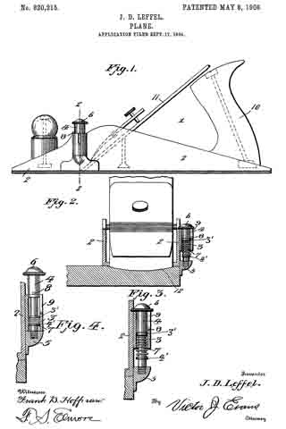
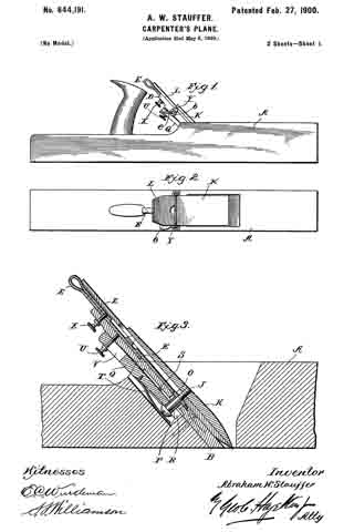
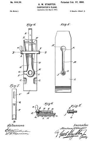
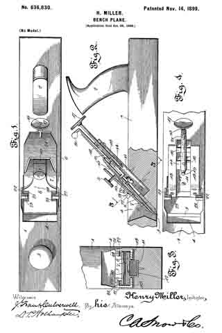
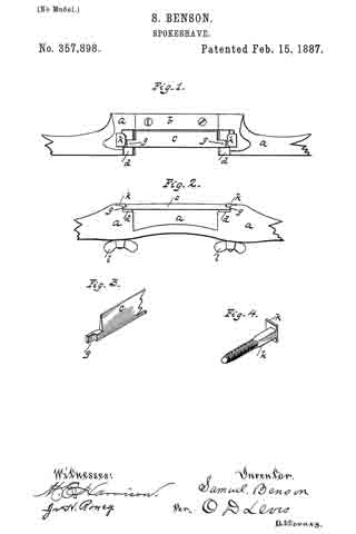
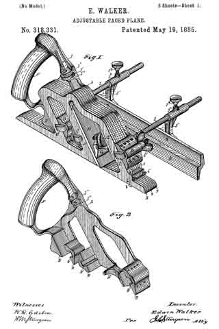
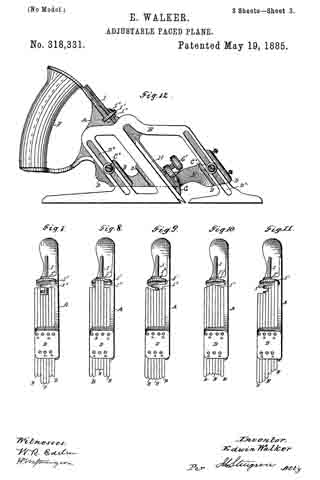
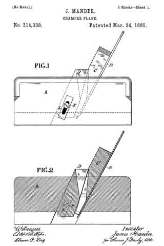
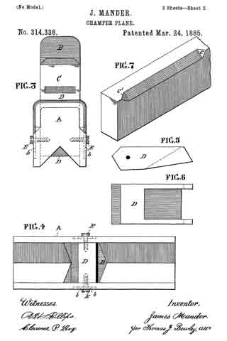
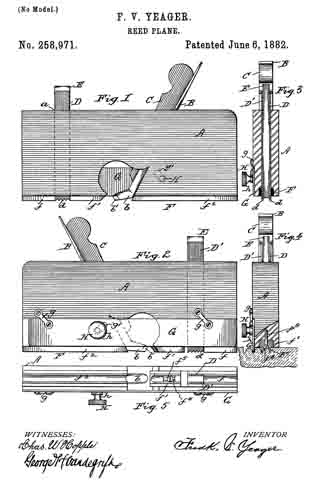
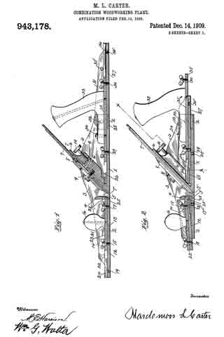
In the accompanying drawings:– Figure 1, is a central side sectional elevation of my improved combination plane showing the same converted into a fore-plane, the same being constructed and arranged in accordance with my invention. Fig. 2 is a similar view partly in elevation, showing the implement converted into at smoothing plane, the rear and forward extensions being adjusted and secured above the level of the base of same. Fig. 3 is a plan view of the converted fore plane, as shown at Fig. 1. Fig. 4; is an end elevation of the same. Fig. 5 is a cross section, taken on the line x x of Fig. 1.
To put my invention into practice and thereby construct a convertible hand plane for carpenters’ and joiners’ use and provide a combination of these planes in one, I form from cast metal a middle section which comprises a flat base 1, upwardly projecting sides 3, extending the entire length of said base, a cross portion 4 located above the throat 5 and an inclined integral rest 6 upon which the bits 7 are held by means of a plate 3 and screw 9 and rigidly secured by a thumb screw 10 operating in connection with a pivoted dog 11.
The above described construction differs but slightly from an ordinary smoothing plane such as are now in common use.
The base 1 of the middle section is rabbeted or reduced to one-half its thickness both at its forward and rear ends 2, and two threaded openings 17′–29′ formed through the base, and suitably located openings in the two side flanges 3 for the reception thumb screws 20 and 32 for the purpose securing the front and rear extensions, as will be fully described hereinafter.
The rear extension of the plane consists of a flat base 27 having side flanges 31, a rabbeted or reduced forward end 28 to register with and engage with the reduced rear end of the plane proper. Formed with this base 27 are parallel arranged dovetailed slides 36, which extend in the direction of its length and are adapted to contain a sliding dovetailed strip 35, in such manner that said strip may move freely therein. This strip 35 is secured rigidly in a certain position by means of thumb screws 29–30, engaging with the threaded opening 29′ in the base 1 of the plane proper and with a similar opening 30′ formed in the base of the extension, as will be best seen by reference to Fig. 1 of the drawings. This rearward extension is further secured and made more rigid with the plane proper by means of thumb screws 32 passing through the side flanges 3 and engaging with threaded openings formed in the flanges 31 of said extension (see Figs. 3 and 5) this making a permanent and rigid connection between the parts. The movable dovetailed member 35 carries an ordinary handle 33, such as are used on all wood planes said handle being attached by a screw 34 at the forward end and by another passing down through the same.
At the rear end of the base 27 of the rear extension is a threaded opening 30, and like openings 35′ are formed in the side flanges of the same, by means of which together with the thumb screws 32, this said extension may be adjusted to the position shown at Fig. 2 of the drawings, having first released the screws 29–30, moved the sliding member 35 back until the thumb screw 29 may engage with the forward threaded opening of the base 27 at which time the side screws 32 are adjusted to make a rigid connection of the parts. This backward movement of the sliding member 35 will bring the handle 33 and adjust the other parts to form the smoothing plane, the whole having been moved forward and on the top of the base 1 of the plane proper, and when in this position the forward extremity of the guides 36 will project beneath an offset 26 formed beneath the inclined bit rest 6′ and prevent any lateral or vertical movement of the extension.
The forward end of the plane proper is also fitted with an adjustable extension, the same consisting of a base 12, rabbeted to register with the front rabbet of the base 1, side flanges 14, parallel dovetailed guides 24 in which a corresponding movable member 23 operates in the direction of its length. This forward extension is secured in line with the plane proper by means of two thumb screws 17 and 18, together with side screws 20 in the same manner as that of the previously described rear extension. The sliding member 23 carries a knob or hand hold 16, common to planes of this class and when the said extension is in position to form a fore plane (as at Fig. 1) said sliding member is projected into a slot 25 formed at the base of the partition 41, and the extension held rigid with the plane proper by thumb screws 17 and 18, engaging the base of said extension and with the base of the plane proper. In addition to these two securing screws 17–18, side screws 20 are used which pass through the fianges of the two members, as will be seen by reference to Figs. 1 and 4.
To adjust the forward extension when the implement is to be used as a smoothing or jack plane the two screws 17–18 are released, the sliding member 23 moved back and the one screw 18 engaged with the threaded opening 19 and the extension more to a position on the top of the base 1 of the plane proper, the rear end of the sliding member 23 entering a pocket 22 formed in the partition at and the rear end of the base resting upon strips 25′ (see Fig. 2). The extension is now secured in this position by the side clamping screws 20.
By placing the front and rear extensions in position as at Fig. 1, a fore plane is formed, the handle 33 being first adjusted to the proper position.
To form a jack plane it is only necessary to adjust the forward extension to the position shown at Fig. 2, leaving the rear extension adjusted as shown at Fig. 1, and in order to convert the implement into a smoothing plane the front and rear extensions occupy a position as shown at Fig. 2.
The advantages of a convertible plane construction, as described are many, as is obvious among which are cheapness, as it takes the place of the three ordinary smoothing planes required for all ordinary carpenters’
practice, and it may be adjusted to occupy the minimum of space in a carpenter’s tool chest.
Various slight modifications and changes may be made in the details of construction without departing from the spirit of the invention. Therefore, I do not wish to confine myself to the construction, shown and described, but wish to claim all such modified forms as would come properly within the general scope of the invention.
Having thus described my invention, what I claim and desire to secure by Letters Patent, is:–
1. A bench plane, comprising a. plane proper, an extension therefor, means for attaching the extension with its sole in line with the plane sole, or with the sole in contact with the inner sides of the main sole plate, and a handle adjustable along the extension.
2. A bench plane, comprising a plane proper, a rearward extension therefor, means for attaching the extension with its sole in line with the plane sole, or with its sole in contact with the inner side of the main sole plate, and a handle adjustable along the extension, in combination with a forward extension, an adjustable knob carried by said extension, and means for locking said adjustable knob and extension to the plane proper.
In testiniony whereof, I affix my signature, in presence of two witnesses.
MARDONIOUS L. CARTER.
Witnesses:
W. G. WALTER,
ARTHUR V. McKEE.