No. 120,212 – Improvement In Carpenters’ Planes (Russell Phillips) (1871)

[paiddownloads id=”188″]120212


UNITED STATES PATENT OFFICE.

_________________

RUSSELL PHILLIPS, OF BOSTON, MASSACHUSETTS.

IMPROVEMENT IN CARPENTERS’ PLANES.

_________________

Specification forming part of Letters Patent No. 120,212, dated October 24, 1871.

_________________

To all whom it may concern:

Be it known that I, RUSSELL PHILLIPS, of Boston, in the county of Suffolk and Commonwealth of Massachusetts, have made an invention of certain Improvements in Carpenters’ Planes; and do hereby declare the following to be a full, clear, and exact description thereof, due reference being had to the accompanying drawing making part of this specification, and in which —

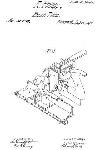
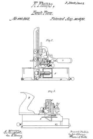
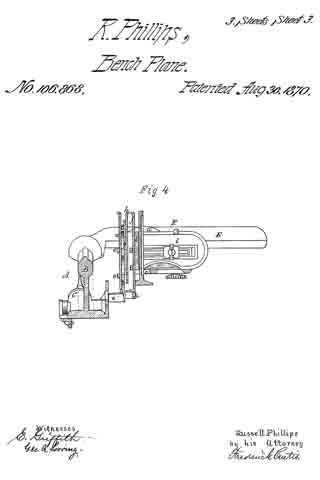
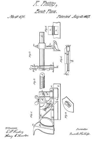
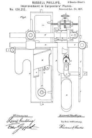
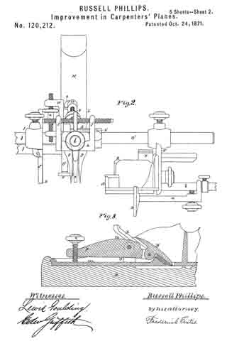
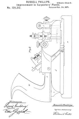
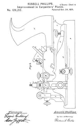
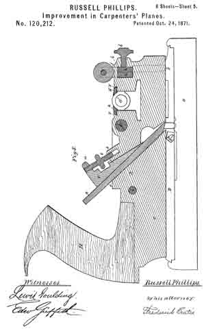
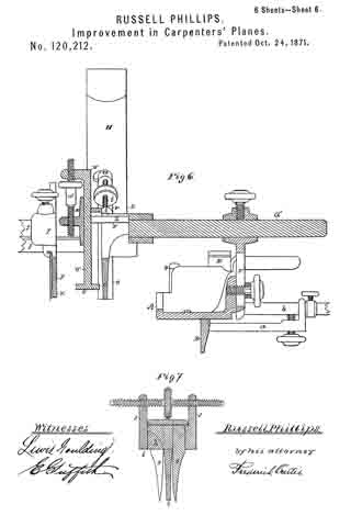
Figure 1 is a plan; Fig. 2, a front elevation; Figs. 3 and 4, opposite side views; and Figs. 5 and 6, vertical sections of a combination plane embodying my improvements. Fig. 7 is a transverse section of the adjustable scoring-spurs, to be hereinafter explained; and Fig. 8, a vertical section of the key of the outermost plow-plane and the device for adjusting the same; Fig. 9, a longitudinal section of the device tor clamping the cutter of the rabbeting-plane, which will be duly explained in the context.

This invention may be considered an improvement upon that for which Letters Patent of the United States have already been issued to me. I have in this instance, as in the former, called the instrument a combination plane, since it embodies three planes of different natures, either of which may be used alone to perform its ordinary functions, if desired, while in the general combination provision is made whereby the three or two of the three planes maybe adapted to execute work unattainable by one, while still further either plane may be removed from connection with its neighbor and used as an independent tool to perform its own individual duty.

The primary elements of this combination consist, first, of a central cross-grooving and plow-plane, such central portion carrying the handle of the combination implement and supporting upon either side, in an adjustable manner, the two other primary elements of the combination, which are a rabbeting-plane and a second cross-grooving and plow-plane, the implement as a whole being susceptible of cutting the tongue and groove in matching stuff, of cutting narrow or extremely wide cross-channels or longitudinal grooves, of performing all the functions of a rabbeting-plane, and finally, of reducing wood to a certain form. in executing moldings by hand, by which much of the labor of roughing out the molding is avoided.

In the drawing accompanying and illustrating this description of my invention, A denotes a metallic rabbeting-plane, substantially of ordinary production with the exception of the absence of a handle and the employinent of a. thumb-guard or hand-rest, B, erected upon its side, the said rabbeting-plane being further distinguished from others of its class by the addition to its under side of an adjustable gauge, D, which converts it into a style of plane known as a “filister”-plane, or those in which the width of the rabbet cut by the tool is governed at pleasure, this gauge being pendent from and controlled by a horizontal arm, a, extending laterally below the plane-bed or plate, which arm in turn is mounted and slides freely upon a rod or bar, b, affixed to and departing laterally from the outer edge of the said plane-bed, and is provided with a set-screw, whereby the two may be clamped together when the desired position of the gauge is insured. Each end ofthe gauge D overlaps the upper edge of that of the plane-bed in order to insure a steady position and relieve the arm a and rod b of the thrusts and strain to which they would be otherwise subjected. A movement of the gauge D to and fro of the plane A with respect to the inner side or the latter determines the width of the cut effected by the iron E of such plane. The plane A is suspended at its outer forward part from a furcated or slotted hanger, F, which is mounted upon and depends from two horizontal parallel rods, G G’, the hanger sliding freely upon such rods, and a set-screw being combined both with the hanger and rods and the plane A, by which both the height and lateral position of such plane with respect to the central plow-plane are varied and determined. This last-named plow-plane, shown at L in the drawing, is the central member of the combination, and bears at rear end the handle H of the combination instrument, such plow-plane being virtually of ordinary construction and composed of an upright blade or sword, c, and a narrow shelf, d, at top, the iron or cutter of this plane being shown at e, while the two horizontal rods or supports G G’ before named depart laterally from this shelf at or near the forward end of the plane, as represented. The second and outermost cross-grooving plane is shown at I in the drawing as simply an upright thin blade or fence, J, carrying in the ordinary manner a cutter, K, this plane I being mounted upon and sliding to and fro of two horizontal lateral guides or rods, f f which extend from the outer side of the central plane I, the said plane being provided with a set-screw, whereby its position upon its guide-bar and its relation to the central plane L are determined. The said plane I serves as a valuable adjunct to the central plane L, inasmuch as the two together are susceptible of cutting a very wide cross-groove, while also, and detached from the other, such plane I is an entirety in itself and is an ordinary cross-groove plane. The scoring-spurs of the central plane L are shown at g g, as disposed at the forward end of such plane and affixed each to a vertical flat plate, h, the two plates overlapping each other and being situated within an orifice, i, created in the sword c and below the shelf d and at right angles to the longest plane of such sword, and remaining upon opposite sides of said sword, and consequently of the cutting-iron carried by it. Each plate h is prolonged into a vertical post, j, while disposed between these posts, and screwing through each, is a right-and-left-threaded screw, by turning which in one or the other direction the spurs are caused to approach to or recede from one another, and thus adapt them to a cutter of any width. In order to adapt the two spurs bodily together to the position of the cutter — that is, to bring the whole into alignment with the general plane of the sword c –I employ a set-screw, l, which enters the orifice i before named and serves to clamp the two spurs firmly into place together at any desired point transversely of the sword and with respect to the cutting-iron e. The cutter-iron E of the rabbeting-plane A is clamped in position upon its bed in by a cap-plate, M, to the under side of which one end of a lever, n, is pivoted, the fulcrum of this lever being a short post, o, erected upon the base of the plane and immediately in rear of the iron E, while screwing downward through the outer and longer arm p of this lever, and abutting again st the said base, is a screw, q, as shown in the drawing. Turning the screw in one direction elevates the longer arm p of the lever and forces the cap-plate M upon the plane-iron E with a powerful pressure, and confines the latter securely in place upon its bed. Reversing the motion of the screw relaxes the pressure upon the parts and permits the adjustment or removal of the cutter. The key of the central plow-plane, which confines its cutter in place, is shown at c in the drawing as a tapering or wedge-shaped block disposed between the cutter and the abutment S, making part of the shelf d hereinbefore mentioned, and the vertical movements of this key in tightening or loosening the cutter are effected by a right-and-left screw, t, which screws at one end into the abutment s and at the other through an arm, u, which constitutes the upper termination of the said key. A turn of the screw in one direction elevates and in the opposite direction lowers the key r, and the action of such key upon the cutter will be at once understood. The depth-gauge of the central plane L is shown at u as a flat horizontal plate, v, :making part of an upright bar, w, which in turn is suspended in an adjustable manner irom a carriage, x, this carriage being supported and sliding within horizontal ways or guides y y formed in the upper forward part of the sword of the plane or the shelf d, making part thereof. The carriage x and the bar u’ of the depth-gauge have each an outstanding lateral shelf, z or z’, the two being disposed opposite each other, while passing through these two shelves is a right-and-left-threaded screw, a’, by means of which the depth of the gauge with respect to the sword and cutter of the plane may be adjusted. It will be observed that the depth-gauge u may be, if desired, fixed immovably to either side thereof.

In the above combination of parts, by lowering the rabbeting-plane A it may be made to serve as a guide or stop to the central or outer plow-planes, or both combined, when used in matching stuff or other purposes, while, as before observed, such plane disposed below the base of the central plane and operating with its adjustable gauge D enables two rabbets to be cut at one and the same time, which will be found of great service in cutting uncommon or irregular moldings by hand, and in exceptional cases in tonguing and grooving. The simple and efficient mode of applying the gauge D to the rabbeting-plane enables its adjustment to be effected instantly, and secures it very firmly to the base of the plane, while it may be made to perform the office of a gauge or guide to either the rabbeting-plane carrying it or to the central plow-plane. The adjustable method of combining the rabbeting-plane and the outer prong-plane with the central plow-plane, as herein shown, enables the combination implement to be set immediately to the proper gauge for cutting the tongue and groove in matching stuff.

I claim —

1. The combination, with the central plane L, of the rabbeting-plane A attached to said central plane in the manner and by means herein shown and described, in order to adjust it both vertically and horizontally in relation thereto.

2. The combination of the three planes A, I, and L in the manner shown and described, so that either or both of the latter two planes may be removed from the former for the purposes stated.

3. The combination, with the plane A, of the adjustable gauge D and the rod or support b under the arrangement shown and set forth.

4. The combination, with the plane L, of the spurs applied thereto in the manner shown and described, to allow them to be adjusted separately or jointly with respect to the cutter of the plane.

5. The combination, with the plane A and its cutter-iron, of the lever n, pivoted to the cap-plate m, inlcrumed to the post o, and provided with the elevating device q, substantially as herein shown and set forth.

6. The combination, with the clamping-key, of the plow-plane I and its abutment of the right-and-left-threaded screw t, in the manner and for the purposes shown and set forth.

RUSSELL PHILLIPS.

Witnesses:
FREDERICK CURTIS,
WILLIAM KEEFE.

No. 106,868 – Improvement In Carpenters’ Planes (Russell Phillips) (1870)

[paiddownloads id=”171″]106868


UNITED STATES PATENT OFFICE.

_________________

RUSSELL PHILLIPS, OF BOSTON, MASSACHUSETTS.

IMPROVEMENT IN CARPENTERS’ PLANES.

_________________

Specification forming part of Letters Patent No. 106,868, dated August 30, 1870.

_________________

To all whom it may concern:

Be it known that I, RUSSELL PHILLIPS, of Boston, in the county of Suffolk and Commonwealth of Massachusetts, have made an invention of a novel and useful implement which I term a Carpenter’s Combination-Plane; and I do hereby declare the following to be a full, clear, and exact description thereof, due reference being had to the accompanying drawings, making part of this specification, and in which —

Figure 1 is a perspective view; Fig. 2, a plan; Fig. 3, a side elevation; Fig. 4, a vertical section.

This invention combines in one implement elementary features now only found in several independent tools, the result being a great saving in space in transportation, as well as in stores and carpenters’ shops, and enabling a mechanic to obtain, at small comparative cost and in a compact and efficient form, the substitutes for several classes of planes.

I have combined in this instrument a rabbeting-plane and an expansible matching-plane, to operate on and prepare boards of various thicknesses, one side of said rabbeting-plane serving as a fence or guide to the latter, as hereinafter explained.

While this invention consists, primarily, of the combination of a rabbeting-plane and an expansible matching-plane, the latter, in turn, will be found to consist of several members, so organized as to enable one to produce a “tongued groove-connection,” called “matching stuff,” a “cross-channel,” or a “plowed groove of any desired dimensions.”

In the drawings accompanying and illustrating this description of my invention, A denotes a rabbeting-plane, substantially of ordinary construction, with the exception of the removal of the handle, and the erection, at or about its center, of a post or standard, B, which slopes forward at a slight angle, and over the iron ofthe plane, which latter is represented at C. The plane A is further distinguished from others of its class by the addition to its under side of an adjustable gage, D, which converts it into a species of plane called “fillister,” or those in which the width of the rabbet cut by the tool is governed at pleasure.

The standard B supports from its upper part a long horizontal lateral bar or arm, E, departing from it at right angles to the length of the plane, such arm supporting the two movable cutter heads or stocks, which, with their adjuncts, constitute the expansible or variable matching-plane before alluded to, the arrangement of parts, as hereinafter explained, being such that both cutter-heads may be moved together or singly upon the arm and away from the rabbeting-plane A, or toward and away from each other thereupon, the side ofthe rabbeting-plane next adjacent to the said cutter-heads serving, under all circumstances, as a gage or “fence,’ so called, to the matching-plane.

The main or primary cutter-carrier is shown at F in the drawings as composed of a plate or portion, a, sliding upon or against the rear side of the arm E, and connned to such arm, upon which it slides, by clamp-nuts and bolts b b, or their equivalents, the inner end of the said plate a terminating in a right-angular bend or head, c, carrying upon its face the “spur or scoring iron,” such spur-iron a’ being secured in position thereupon by side projections or hooks, e e, and a set-screw, f, as represented, and performing the duties of preparing the way for either one or both of the matching cutters, as the case may be.

Upon the front or inner face of the cutter-carrier F or its cutter-head c, I apply a flat plate or second cutter-head, g, this latter object sliding vertically upon the head c, and being confined thereto by a set-screw or other device. The cutter-head g carries upon its inner face a cutter or iron, h, for cutting or plowing a groove, the relationship of the two cutter-heads being such that the head g may be lowered into a working position, or elevated above the same, while the cutter It may be raised or lowered with respect to its head, according to the depth of cut required, it being understood, as before stated, that when the said cutter (or its companion, to be duly referred to) is at work the side or fence i of the rabbeting-plane A serves as a guide or gage to determine the width of the cut thus made.

The iron or cutter It is composed of an upright flat plate, the lower part of which is bent into an angular sloping portion, which, constitutes its cutting-edge, the cutter by this means saving the necessity of employing two spurs to prepare its way, while the lower edge of the head g serves as a “sword,” so called, to determine the thickness of the shaving cut by the said cutter.

The cutter h, may be employed alone, in connection with the rabbeting-plane, to cut a channel, whether such groove be an ordinary cross-groove or the groove required to receive the tongue of the next adjacent board in “matching stuff,” or the said cutter may be employed in connection with the cutter to cut away one side of the tongue used in said operation of matching stuff; or, again, should occasion require, the cutter or iron h may be lowered and work in conjunction with the rabbeting-plane A, thus cutting at one and the same time a rabbet and groove or channel.

The second cutter, before mentioned, is shown at j in the accompanying drawings as mounted upon the inner face of a second cutter-head, k, which makes part of a carrier, l, mounted and sliding upon the first carrier, F, and confined thereto, by clamp-nuts or set-screws, in any proper manner, it being observed that the construction and relationship of this latter cutter-carrier and head with respect to the former being substantially the same as the former in respect to the arm or support E, before mentioned, it being observed that while the cutter or tool may be moved toward or away from the rabbeting-plane, for the purpose of cutting channels of varying width, the two cutters may be separated or contracted, in order to cut a tongue of any given width up to a certain extent.

Upon the outer or remote side ofthe second cutter-head, k, is disposed an adjustable gage for determining the depth of the cut made by either one or both the cutters h or j, (in connection with the rabbeting-plane as a side gage,) to produce a cross-channel or plow a groove.

As it becomes necessary to produce a sword to regulate the thickness of the shaving cut by the second cutter or iron, j, I form it (the sword) upon the under side of a fiat plate, o, which in turn is suspended from the under side of the carrier l, applied adjustably thereto, and confined in place by set-screws or their equivalents, in order that the lateral position of the said sword with respect to the said cutter j may be varied, as it sometimes becomes desirable that this sword shall travel in the center, or thereabout, of the groove or channel formed by such cutter.

Upon the upper side of the rear extremity of the sword, which is shown at p, or its supporting-plate o, I mount the handle of the combination-instrument, such handle being represented at q in the drawings.

An instrument constructed and organized as above explained may be used as a rabbeting-plane, or fillister simply.

By lowering the cutter h, to the proper extent and employing the side of the rabbeting-plane as a guide or gage, a cross-channel may be cut or a groove may be plowed.

By lowering the second cutter, j , and adjusting the distance between the two to the width of tongue required in machine-stuff, such tongue will be cut to any desired gage, or, as before stated, the second cutter, j, maybe employed alone, in connection with the spur-iron a’, to cut a channel or groove.

For extreme variations in the extent of cuts made by my present invention, I shall adapt cutters of varying widths; but it will be evident that considerable variations maybe made without removing the cutter at the time in use.

In the use of the rabbeting-plane alone, the cutter-head c should be inverted end for end to serve as a gage.

Although I have in the present instance represented one of the cutter-carriers as supported and sliding upon the arm E and the other carrier applied in similar manner to the first, I would remark that I intend applying each carrier by itself to the bed or frame of the tube.

I claim —

The herein-described carpenter’s plane.

RUSSELL PHILLIPS.

Witnesses:
EDW. GRIFFITH,
FRED. CURTIS.

No. 67,671 – Improvement In Carpenters’ Planes (Russell Phillips) (1867)

[paiddownloads id=”132″]67671


United States Patent Office.


RUSSELL PHILLIPS, OF GARDINER, MAINE, ASSIGNOR TO HIMSELF AND NATHAN WESTON.

Letters Patent No. 67,671, dated August 13, 1867.
_________________

IMPROVEMENT IN CARPENTERS’ PLANES.

_________________

The Schedule referred to in these Letters Patent and making part of the same.

_________________

TO ALL WHOM IT MAY CONCERN:

Be it known that I, RUSSELL PHILLIPS, of Gardiner, in the county of Kennebec, and State of Maine, have invented a new and useful Improved Joiners’ Plough ; and I hereby declare the following to be a full, clear, and exact description thereof, which will enable others to make and use my invention, reference being had to the accompanying drawings, forming part of this specification, in which —

Figure 1 shows a side elevation of my invention.
Figure 2, a portion of the top of the horizontal arm, having the graduated scale.
Figure 3 is an end view of my invention, and a view of the top of the end and slides.
Figure 4, a view of a portion of the reverse side of fig. 1.
Figure 5, an edge view of the iron or cutter.
Figure 6, a portion of the adjustable guide or gauge.

Same letters show like parts.

My invention has relation to that tool employed by certain mechanics, joiners, &c., called a plough, and consists in certain improvements thereupon, which may be separately or conjointly used.

I will now describe in detail the different improvements combined in my invention. a shows the groove in which the iron or cutter is placed. It is there secured by means of the clamp b and slide c. Fig. 4 shows the manner in which the slide c is held in place, being by means of a slot and a lip, d, on the side opposite to the one shown in fig. 1. The lip d overlaps the edge of the slot, shown in fig. 4. e is a small projection, to rest against the end of the cutter, so that its edge shall not become dulled by striking or touching any part of the stock. The cutter is fully described hereafter. The cutter, being placed in the groove a, is secured as follows:

As illustrated in fig. 4, the slot in which the slide c moves is curved, so that when the slide is pressed downward, or toward the bottom of the plough, the clamp b is pressed upon the cutter; and when the slide is moved up, the clamp is released or loosened, and its pressure upon the cutter taken away. The clamp b swings on its pivot f. Place the cutter in the groove a, press the slide downward, thus forcing the clamp b upon the cutter, and the cutter is held in place. In this method there is this advantage: With the old form of fastening the cutter or iron, when the wedge that holds it is driven inward by the blow of the hammer or other implement the entrance of the wedge within the stock carries with it, somewhat, the cutter, so that when the cutter has once been adjusted as the mechanic desires, it is made to project further, by being carried inward with the wedge which holds it. Besides this inconvenience, it is difficult to adjust readily. With my invention, the cutter is placed in the desired position, so as to cut into the lumber the desired depth, and can then be immediately fastened by pressing the slide c downward. Moreover, as the clamp b does not slide at all, but simply pushes against the cutter, the cutter is not moved in the least from the desired position, but remains as placed by the user. g, fig. 5, shows the iron or cutter; this has a cutting edge at both ends. These two can be made of different sizes and widths, as seen in the drawing, so as to cut grooves or channels of different widths and sizes. It has a groove, h, to fit over the edge i, to aid in holding it securely. The end of the cutter not employed passes into the recess behind the projection e, and thus its edge is kept from injury till wanted. j is a thumb-piece, for convenience in placing the cutter in its place, and to strike upon with a hammer to move the cutter up or down slightly when it is held by the clamp b. k k are the cutting edges of the iron. l l l l show points projecting beyond the edges k k, which enable the iron to do its work not only with but also across the grain of the wood. These points are sharp, and cut the fibres of the wood before they are reached by the edges k, and thus prevent tearing or breaking out of the work. A shows the single horizontal arm employed in my invention, and upon which the guide or gauge B slides. Upon its top is a channel, with the graduated scale, so that the distance that the gauge is set from the cutter g can be accurately adjusted. Upon this there is no screw-thread, as upon the old form of plough, and, as before remarked, I use but a single arm. This admits of a much easier, more accurate, and readier arrangement for use. The gauge or guide B is made of metal, and has a portion, n, which turns on a hinge, and can be lifted up so as to leave the space o. The object of this will be hereafter described. p are slides, one on each side of the stock of the plough, near the forward end, moving in recesses, and held at any point by the thumb-screw q, which slides in the slot r, shown in fig. 1 by the dotted lines. These slides have at their bottoms the horizontal plates s, one on each side of the plate t. The combination of these devices forms a gauge by which the degree of the penetration of the cutter g into the wood can be governed. By loosening the thumb-screw q, the slides may be raised or lowered, as desired, on either side of t, (see fig. 3.) and, as seen in fig. 1, the cutter is intended to rest against the side of t, so that the depth of the groove to be cut can thus be exactly controlled, and measured by the graduated scale x on the end of the stock, (see fig. 3.) Most of the work to be done by this tool is near the edge of boards or other wood. In such a ease it might happen that the gauge or guide B could not be brought sufficiently near the plate t on account of the projection of the horizontal plates s. This I obviate by the arrangement shown in fig. 6, before described. When the trap an is lifted, as seen in the drawing, the gauge B can be brought quite close to t, one of the plates s entering the space o. In use, one hand of the mechanic rests upon the guide B, where a wooden handle is supplied. The handle upon the stock is seen at D, being placed at the end of the stock, and lower down than is ordinary, with the view that the force applied to the tool is all or nearly all exerted in a horizontal direction, which lessens the labor of using the plough, and makes it more effective. The handle is secured by the removable bolt u, so that if broken the handle can easily be taken off and another substituted. All the parts described, except the arm A, handle D, and a portion of the guide B, are made of metal, which makes the whole tool cheaper, less cumbersome, stronger, and more convenient. The clamp b being made of metal, quite smooth, and slightly rounded, enables the tool to clear itself quite readily of the shavings made in using it. The method of confining the gauge or guide B at any desired point is by the use of the thumb-screw m.

What I claim as my invention, and desire to secure by Letters Patent, is —

1. The reversible cutter shown in fig. 5, as and for the purposes specified.

2. The arrangement of the two slides p p, thumb-screw q, slot r, plates s s, graduated scale x, and plate t, as and for the purposes set forth.

RUSSELL PHILLIPS.

Witnesses:
WILLIAM HENRY CLIFFORD,
HENRY C. HOUSTON.