No. 143,737 – Improvement In Splint-Planes (Henry L. Weagant) (1873)

[paiddownloads id=”218″]143737


UNITED STATES PATENT OFFICE.

_________________

HENRY L. WEAGANT, OF MORRISBURG, CANADA, ASSIGNOR OF TWO-THIRDS OF HIS RIGHT TO STEPHEN B. FELL AND ROBERT LYLE, OF SAME PLACE.

IMPROVEMENT IN SPLINT-PLANES.

_________________

Specification forming part of Letters Patent No. 143,737, dated October 14, 1873; application filed August 29, 1873.

_________________

To all whom it may concern:

Be it known that I, HENRY LUDWICK WEAGANT, of Morrisburg, in the county of Dundas and Province of Ontario, Canada, have invented new and useful Improvements in Splint-Planes; and I do hereby declare that the following is a full, clear, and exact description of the same.

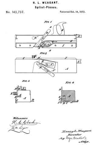
By my invention a plane or slat-cutter is provided which will produce at each cut a slat, perfectly formed, beveled, properly straightened out, and then receiving the proper bend to facilitate its being woven, reference being had to the annexed drawings, where similar letters of reference indicate like parts, and where —

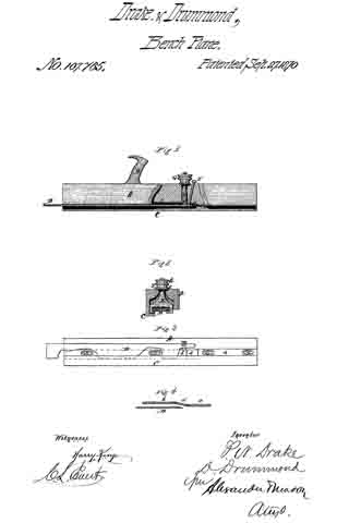
Figure 1 represents a side view, Fig. 2 a bottom view, and Fig. 3 an end view, of my slat-cutter. Fig. 4. represents a section of my slat-cutter on line A A.

A is the body of the plane or slat-cutter, in which is formed, as shown in Figs. 1, 2, and 4, a recess, A’. In this recess is placed the plane-iron B for cutting the slats, slotted in the ordinary manner, and further secured by a cap or stiffening piece, C. D D’ are the beveling-knives, slotted and secured, one to the side and the other to the bottom of the plane, and arranged so as to cut the beveled edges of the slats. E is a groove formed in the side of the plane, through which the slat just cut passes. F is what is termed the “governor,” placed in the throat E’ of the groove E, and secured preferably by means of a plate or washer and screw, its purpose being to straighten the slats as they pass irom the plane-iron B, the spring G materially assisting in doing this. H is a recess formed in the throat, and serving to give the slat when straightened the proper bend to enable it to be woven. I I are guides to keep the plane in its proper course, and K K’ handles for working the plane or cutter, L being another handle, which may be hinged to the stock, if required.

The operation of my invention is so simple as hardly to require any explanation, it being worked in the same way as an ordinary plane, and being applied to the edge of a board, the thickness of which is the required width of the slat.

The slat, being divided from the board by the iron B, has at the same time its edges beveled by the cutters or knives D D’. It then passes up over the governor F, and between it and the spring G, being thereby straightened, and, the end being caught in the recess H, is thereby slightly bent again, as required.

What I claim is as follows:

The combination of the plane-iron B and beveling-knives D D’ with the governor F, spring G, and recess H, as and for the purposes set forth.

HENRY L. WEAGANT.

Witnesses:
ROBERT LYLE,
ROBERT S. WEAGANT.

No. 107,765 – Improvement In Splint-Planes (Philander N. Drake And David Drummond) (1870)

[paiddownloads id=”160″]107765


United States Patent Office.


PHILANDER N. DRAKE AND DAVID DRUMMOND, OF MCGREGOR, IOWA.

Letters Patent No. 107,765, dated September 27, 1870.
_________________

IMPROVEMENT IN SPLINT-PLANES.

_________________

The Schedule referred to in these Letters Patent and making part of the same.

_________________

To all whom it may concern:

Be it known that we, PHILANDER N. DRAKE and DAVID DRUMMOND, of McGregor, in the county of Clayton and in the State of Iowa, have invented certain new and useful Improvements in Splint-Plane or Slat-Cutter; and do hereby declare that the following is a full, clear, and exact description thereof, reference being had to the accompanying drawing and to the letters of reference marked thereon, making a part of this specification.

Our invention relates to that kind of planes used in cutting thin strips or slats for rustic shades, and other purposes, and consists —

First, in placing the cutter under the bottom of the plane, level with the edge of the board from which the strips or slats are to be cut;

Second, in the construction of the mechanism for holding the cutter in its place; and

Third, in the construction of the mechanism for regulating the thickness of the strips or slats to be cut.

In order to enable others skilled in the art to which our invention appertains to make and use the same, we will now proceed to describe its construction and operation, referring to the annexed drawing, in which —

Figure 1 is a side view, part in section, of our plane;
Figure 2 is a transverse vertical section; and
Figure 3, a bottom view of the same.
Figure 4 shows the end of the cutter, with the channel-plates in the plane.

A represents the body of our plane provided with a handle, B.

Along one side of the body A is secured a bar, C, projecting below the plane a suitable distance to form a guard or guide for the tool.

Between the under side of the plane A and the bar C is formed a groove, in which the inner edge of the cutter D is inserted, said cutter being laid level under the lower side, or against the lower side of the plane A.

The cutting-tool D is held by means of a stirrup, E, constructed as shown in fig. 2, and passed up through the plane A, with a screw-shank at its upper end, which projects above the plane.

On this screw-shank is placed a thumb-nut, G, by means of which the stirrup is raised so as to firmly bind the cutting-tool. The pitch of the cutting-edge of said tool is regulated by means of two inclined screws, I I, passing through the plane A and bearing against the upper surface of the cutter, one on each side in front of the stirrup E.

The tool-bit being on a level with the edge of the board, it splits with less liability to break the fiber on the back of the slat. When it is to be taken out to sharpen, it can be put back to its place accurately and cut all the work of uniform thickness.

The two screws, I I, forcing the cutting-edge of the cutter to the desired position for uniform thickness, may, of course, remain in the same position for any length of time without change, even though the cutter is taken out and replaced again.

In the channel on the under side of the plane A, between it and the cutter D, are placed three channel-plates, a, b, and d, the relative positions of which are plainly indicated in fig. 4. The object of these plates is to further enable us to vary the thickness, if we desire to do so.

The back or upper side ofthese plates may be provided with inclines to enable them to be pushed forward or back.

The middle plate d is made so that it can readily be taken out and another of different size substituted.

Having thus fully described our invention,

What we claim as new, and desire to secure by Letters Patent, is —

The combination, with the stock A, of the flat-laid tool D, channel-plates a b d, stirrnp E, nut G, and screws I I, all constructed to operate substantially as set forth.

In testimony that we claim the foregoing, we have hereunto set our hand and seals this 26th day of March 1870.

PHILANDER N. DRAKE. [L. S.] DAVID DRUMMOND. [L. S.]

Witnesses:
A. J. JORDAN,
ORLANDO McCRAREY.

No. 19,229 – Tool For Manufacturing Splint Baskets (Artemas Baker) (1858)

[paiddownloads id=”70″]19229


UNITED STATES PATENT OFFICE.

_________________

ARTEMAS BAKER, OF TEMPLETON, MASSACHUSETTS.

TOOL FOR MANUFACTURING SPLINT BASKETS.

_________________

Specification of Letters Patent No. 19,229, dated February 2, 1858.

_________________

To all whom it may concern:

Be it known that I, ARTEMAS BAKER, of Templeton, in the county of Worcester and State of Massachusetts, have invented a new and useful Tool for Riving Out Basket Stuff, of which the following is a full, clear, and exact description, reference being had to the accompanying drawings, making part of this specification, in which —

Figure 1 is a. plan of the bottom of the tool. Fig. 2 a longitudinal vertical section of the same on the line x, x, of Fig. 1. Fig. 3 a transverse vertical section on the line y, y, of Fig. 1.

In manufacturing thin strips of wood to be used for basket stuff, chair bottoms and for other purposes, it has been customary to rive out the slip and afterward dress or finish its surface, this causes considerable delay and expense in the preparation of the stuff. It is obvious that if a plane is used having an opening in the top of the stock for the slip or shaving to pass out at, as in the ordinary bench plane, that the slip must be bent up so abruptly as it is separated from the piece of stuff that the fibers of the wood will be broken or crippled and the value of the article produced be materially diminished.

The object of my present invention is to produce a tool with which these slips may be cut from at piece of stuff with their surfaces smoothed at one operation.

That others skilled in the art may understand and use my invention I will proceed to describe the manner in which I have carried out the same.

In the drawings A, is the stock, longitudinally through which for a considerable portion of its length is formed a groove or recess B, which is open at the rear end of the stock at a, for the passage of the slip of wood after it has been separated from the large piece of stuff. To the bottom or face of the stock is secured a guard plate C, having an inclined edge at b, alongside of this plate is the cutting iron D made of thicker plate than the guard C, its cutting edge at c, is beveled on the inner side (as in Fig. 3) and inclines to correspond with the edge b, — the screws d, by which this iron is held to the stock pass through slots e, in the iron so that as the edge is worn or ground down the iron may be advanced and the edge c, be kept in the proper position, this edge is kept at such a distance below the edge b, as will give the proper thickness to the slip — overlapping parts of the guard C, and the iron D is a guide E, which is secured to the stock by screws f, the straight edge g of this guide, runs in contact with the side of the plank from which the slips are being cut, and the edge c, being inclined at an acute angle to the guide or to the path of the plane separates the slip from the piece of stuff’ by cutting the fiber and not by riving or rending it oft, and the surface from which the slip is taken off is left smooth so that when the next slip is taken off, both of its sides will be smooth enough for use without any subsequent. finishing. The slip as it is separated from the plank passes through the groove B, out from the plane at a, without having been bent up in such. a manner as to injure the integrity of its fibers.

I am aware that planes have been used having the edge of the iron inclined to the path of the plane. Therefore I do not claim this feature alone; but

What lf claim as my invention and desire to secure by Letters Patent is —

The above described tool consisting essentially of the guide E — the plate C, and the horizontal iron D, with its inclined edge c, in connection with a horizontal recess B, and opening at operating in the manner and for the purpose substantially as set forth.

ARTEMAS BAKER.

Signed in presence of —
ERASTUS O. EDERY,
DEXTER GILBERT.

No. 50,947 – Improvement In Splint Planes (Harrison Ogborn) (1865)

[paiddownloads id=”109″]13957


UNITED STATES PATENT OFFICE.

_________________

HARRISON OGBORN, OF RICHMOND, INDIANA.

IMPROVEMENT IN SPLINT-PLANES.

_________________

Specification forming part of Letters Patent No. 50,947, dated November 14, 1865.

_________________

To all whom it may concern:

Be it known that I, HARRISON OGBORN, of Richmond, in the county of Wayne and State of Indiana, have invented certain new and useful Improvements in Planes for Cutting Blind-Slats, Splints for Baskets, and other similar work; and I do hereby declare that the following is a full, clear, and exact description of the construction and operation of the same, reference being had to the annexed drawings, made a part of this specidcation, and the letters of reference thereon, the same letters referring to identical parts.

Figure 1 is a side view of the plane when arranged for use as a jack-plane, showing the bottom of the plane used for cutting slats, &c.
Fig. 2 is a longitudinal vertical section of the plane through the line y y, Fig. 4. Fig. 3 is a like section through the line x x, Fig. 4. Fig. 4 is a transverse section of the stock. Fig. 5 is a view of the knife employed for splitting the slats or splints. Fig. 6 is a view of a knife for splitting the slats with beveled edges. Fig. 7 shows the adjustable plate for determining the cut and removing splinters that wedge in the plane. Fig. 8 is a sectional view of the knife or bit used on the splint-plane. Fig. 9 is a top view of the same.

The stock of the plane A is arranged for two bits, and having two faces. One of these is an ordinary jack-plane, as shown in Figs. 1 and 2.

The handle B is adjustable, and may be made to stand perpendicularly to either of the plane-faces. It turns upon a rod, M, and, swinging in a notched recess in the corner of the stock, is held perpendicularly to either face by an ordinary window-catch, of which there are two shown, Figs. 2 and 3, G G’.

On the bottom of the face of the splint-plane are shown two adjustable guides, one square, the other beveled. One of these, according to the character of the work, is used on the left-hand side of the plane, held in place by screws with oblong heads working in slots in the ends of the guides, as shown in Fig. 1.

D is the knife or bit ofthe splint-plane, held in place by the same kind of screws working in slots, so as to allow the adjustment of the knife by the aid of the set-screws N N.

E shows the bit of the jack-plane, of ordinary construction, and arranged in the usual manner.

K is an adjustable plate, held by similar screws on the face, allowing its adjustment to the knife as they are worn away in use, to which is attached the set-screw passing through the stock and working in a collar on the upper surface of the plane. This arrangement makes it easy to withdraw the plate in case a splinter should wedge in the space between the plate and knife.

The knives H I, one straight, the other bent for cutting beveled edges, work as shown in Figs. 3 and 4. The knives are held in place by the wedge L, and the points protrude through narrow slots in the plate K. (Shown in Fig. 1.) The bent knife its the beveled point of the wedge L. When the straight knife is used the wedge goes on the right of it, but on the left side of the bent knife. There are one or more of these knives used, according to the number of slats intended to be cut from the board. The bent knife is used with the beveled guide.

In operating with this plane, the boards, being dressed, are cut into narrow strips of the proper width on their edges by the knife H, or so that the slats shall have beveled edges, by the knife I. The splints are cut by the knife or bit D passing between the plate K and the bit D. Rising over D, they are bent in a contrary direction, and passing out under the lower surface of the plane they are flattened and delivered free from curves or tendency to twist.

Having thus fully explained the character and operation of my improvements, what I claim as my invention, and seek to secure by Letters Patent, is —

1. The arrangement, in a splint-plane, of the plate K, bit D, and one or more splitting-knives, and guide C, all constructed and combined substantially as and for the purpose set forth.

2. The arrangement, in a splint-plane, of the piate K, bit D, beveled guide C and one or more bent knives, I, all constructed and combined substantially as and for the purposes set forth.

3. The combination of the plane-stock A and adjustable handle B, so constructed with the rod M and springs G and G’ as to be capable of being arranged perpendicularly to the two faces of the plane, substantially as described. In testimony whereof I have signed my name to this specifcation in the presence of two subscribing witnesses.

HARRISON OGBORN

Witnesses:
R. MASON, BEN FIELD.

No. 51,153 – Improvement In Splint Planes (James Dempsey) (1865)

[paiddownloads id=”110″]51153


UNITED STATES PATENT OFFICE.

_________________

JAMES DEMPSEY, OF RICHMOND, INDIANA.

IMPROVEMENT IN SPLINT-PLANES.

_________________

Specification forming part of Letters Patent No. 51,153, dated November 28, 1865.

_________________

To all whom it may concern:

Be it known that I, JAMES DEMPSEY, of Richmond, in the county of Wayne and State of Indiana, have invented certain new and useful Improvements in Planes for Cutting Slats for Window-Shades or other Thin Splints of Wood.

The object of my invention is to construct a splint-plane that shall be as readily adjustable as the ordinary hand-plane, and have such a channel for the splint when out as that it shall not be broken by being thrown abruptly upward over the knife. In other planes either the splint is liable to be broken or the knife placed horizontally is ditiicult of adjustment. Another object is to provide that the splint when cut shall be perfectly smooth and fit for use as it comes from the plane. Both of these objects are, I believe, accomplished by my im-provements.

To enable others skilled in the art to make and use my invention, I will describe its construction and operation, reference being had to the annexed drawings, making a part of this specification, and the lettering thereon.

In the different plans the same letters refer to identical parts.

Figure 1 is an elevation showing the half of the plane when divided into two parts, on the line x x, Fig. 3, where the plane as constructed is divided. Fig. 2 is a longitudinal section on the line x x, Fig. 3. Fig. 3 is a transverse section upon the line y y, Fig. 4. Fig. 4 is a plan of the plane, showing the bottom part, the guide being represented as cut away in part. Fig. 5 is a plan showing the construction of the bit. Fig. 6 is a plan showing the construction of the spring in the bottom of the plane.

The stock is made in two parts, A and B, of wood, joined by the dowel-pins L L and by screws.

C is the bit, of which about two inches of the lower end is nearly horizontal, but depressed at the point sutliciently to give the cutting-edge the requisite draft into the wood. It is bent at N, rising and passing transversely through the stock. It is adjusted by the set-screw H, and held firmly in place by the wedge M and clamps E E. These clamps catch upon the bit below and hold it firmly by stress of the nuts E’ E’ upon their upper ends. This bit is constructed with the rectangular slot G, which opens from the angle and extends upward about three inches, and having a width of about seven-eighths (7/8) of an inch. Over this slot the spring G is placed, bent upward and having the upper extremity, near O, turned slightly down, so as to hold firmly to the splint as it passes, and yet guide it through the slot at O. Upon the bottom of the plane, attached by a set-screw working in the slot F, is the spring D, the tongue extending above the bit and forming a guide for the splints as cut. On the bottom of the side B of the stock is fastened a guide, P, made adjustable by the set-screws and slots K.

On the under side ofthe wedge M, at its lower extremity, is cut a groove, of the width of the slot in the bit C, and terminating a little above the point ofthe spring G. Through this groove passes the splint.

In operating with the plane the guide p is set at one-half the width of the splint to be cut from the line x x. The bit C and spring D being adjusted by the set-screws I and H to cut splints of the required thickness, the bit C is held firmly in place by the wedge M and clamps E. The splint, being cut by the sharp point of the bit, rises above it, passing under the tongue of the spring upward through the groove in the under side of the wedge M, over the spring G. It passes through the bit C at O, and is carried through the stock in the groove D, passing out behind the plane unbroken and highly polished by the combined action of the cutter-bit and spring.

Having fully explained my mode of constructing and operating splint-planes, what I claim as my invention, and seek to secure by Letters Patent, is —

1. Constructing the bit C of a splint-plane with the slot and spring, substantially as described.

2. The arrangement of the spring D, clamps E, wedge M, stock A B, with the bit C, all of them constructed and combined substantially as and for the purpose described.

In testimony whereof I have signed my name to this specification in the presence of two subscribing witnesses.

JAMES DEMPSEY.

Witnesses:
R. MASON,
JOHN S. HOLLINGSHEAD.