No. 17,118 – Improved Lubricator For Bench Planes (Hiram Strait) (1857)
UNITED STATES PATENT OFFICE.
_________________
HIRAM STRAIT, OF COVINGTON, KENTUCKY.
IMPROVED LUBRICATOR.
_________________
Specification forming part of Letters Patent No. 17,118, dated April 21, 1857.
_________________
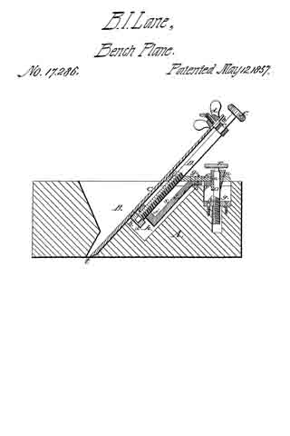
To all whom it may concern:
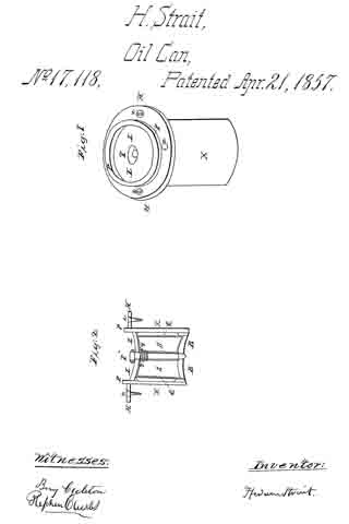
Be it known that I, HIRAM STRAIT, of Covington, Kenton county, Kentucky, have invented a new and useful Oiling Machine or Apparatus; and I do hereby declare that the following is a full and definite description and illustration of the same, reference being had to the accompanying drawings, in which similar letters stand for similar parts.
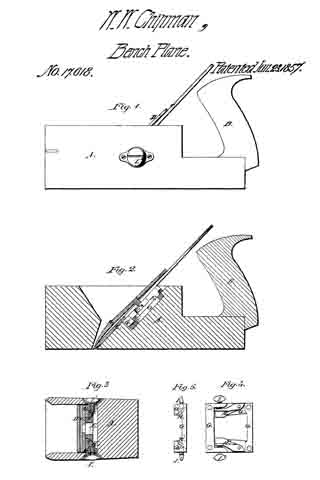
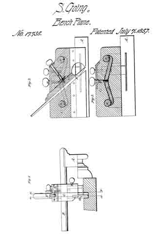
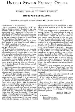
Figure 1 is a perspective, and Fig. 2, a vertical section of this oiling-machine, showing the relative position of its parts.
X is a cylindrical oil cup or vessel open at the top and bottom.
P is a vertical projection of its top for striking with a hammer, so as to loosen the bits of planes when they require sharpening, and R is a horizontal projection with several screws, z z, to fasten it to a plane-stock or journal-box.
L is its lid, which may be part of the cup, or separate, and is slightly concaved to receive the oil and set down in the cylinder a piece, so as to allow the blow of a hammer on the projection B; and B is its sliding and adjustable bottom.
T is a thumb-screw that passes freely through the lid L and screws into the bottom B, so as to raise it when turned one way and lower it when turned in a contrary direction.
To support the lid in its place and prevent the bottom from rotating with the thumb-screw, two or more guides, G G, are attached to the inside of the cup at equal distances, and the bottom is fitted to receive them and slide freely either up or down. The thumb-screw may be surrounded by a spiral spring, y y, to keep the bottom always fully extended.
S is a sponge or any other porous and elastic material saturated with oil, or a porous bag filled with oil, interposed for pressure between the lid L and bottom B. When the bottom raises, the pressure on the sponge increases, and when its falls, decreases. The oil is poured first onto the lid and then passes down into the sponge, and then its flow onto a journal or the face of a plane-stock is regulated by the pressure given by the thumb-screw.
This oiler is applicable to plane-stocks and journal-boxes. In plane- stocks it may be placed in front or behind the bits, or in front of the stock. When let into the stock it may extend clear through to the working-face, or it may extend near to it, and then the face immediately under it may be perforated so as to allow the oil to flow through and spread over it. The oil-cup may have a permanent and perforated bottom immediately under the sliding one, if required. When applied to journal-boxes, the lower part of the oil-cup X under the sliding bottom B may be contracted to a small aperture, and in plane-stocks expanded to their width. Any material that will saturate with oil and discharge it by pressure may be used in place of sponge.
This oiler may be attached so as to operate either vertically or horizontally. The lid may merely rest on the guides or be screwed firmly in its place.
The oil-cup may be square, oval, oblong, or of any other irregular form, and then the guides may be dispensed with and the lid rest on a projecting shoulder or points attached to the sides.
The oiler can be cast onto plane stock and journal-boxes when they are cast.
What I claim in this invention, and wish to Secure by Letters Patent of the United States, is —
The oil-cup X, with its sliding bottom B, thumb-screw T, and guides G, in combination with porous oil-bags or pieces of sponge S, or any other porous and elastic material saturated with oil, and the spring y, substantially as herein specified.
HIRAM STRAIT.
Witnesses:
BENJ. EGELSTON,
STEPHEN CHARLES.