No. 895,796 – Adjustable Plane (Owen J. Sund) (1908)

[paiddownloads id=”656″]895796


UNITED STATES PATENT OFFICE.

_________________

OWEN J. SUND, OF TACOMA, WASHINGTON.

ADJUSTABLE PLANE.

_________________

895,796. Specification of Letters Patent. Patented Aug. 11, 1908.
Application filed May 16, 1907. Serial No. 373,931.

_________________

To all whom it may concern:

Be it known that I, OWEN J. SUND, a citizen of the United States, residing at Tacoma, in the county of Pierce and State of Washington, have invented certain new and useful Improvements in Adjustable Planes; and I do hereby declare the following to be a full, clear, and exact description of the invention, such as will enable others skilled in the art to which it appertains to make and use the same.

This invention relates to improvements in planes and particularly to adjustable planes of the type known as “carpenter’s nosing planes.”

The invention comprises the production of a cutter-holder and means for varying the width at which the same is designed to operate.

The invention further comprises the production of a plurality of cutter-holders that are designed to register with each other for providing means for varying the width of cut of the cutters.

The invention still further comprises the production of a plurality of cutter-holders designed to be adjustably secured together, and means for varying the adjustment, for regulating the width of cut desired.

The object in view is the production of a plane for forming rounded edges that may be adjusted to any desired width and without changing the cutting tools used.

A still further object of the invention is the production of a nosing plane formed in a plurality of parts, and means for adjustably securing same together, and cutters that are designed to extend past each other, in order to form a cutting surface of varying width.

With these and other objects in view, the invention comprises certain other novel constructions, combinations and arrangements of parts as will be hereinafter more fully described and claimed.

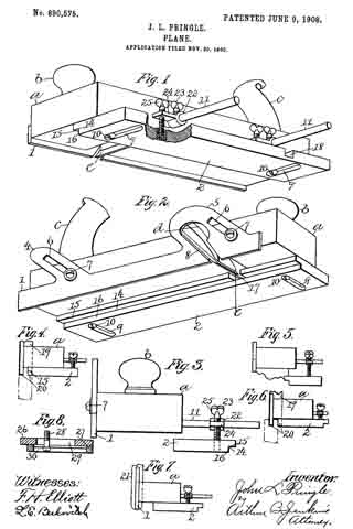
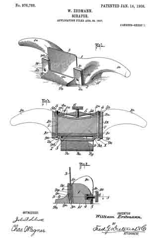
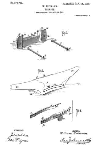
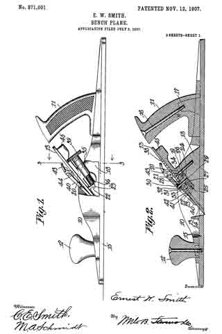
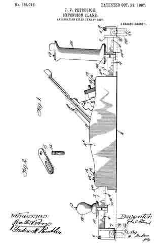
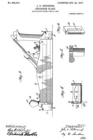
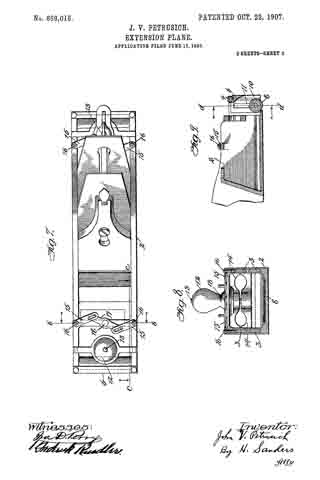
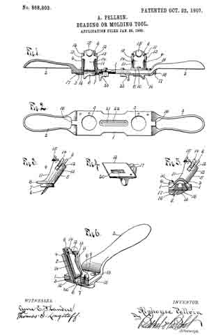
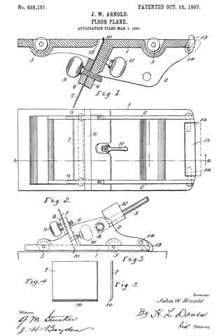
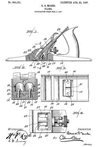
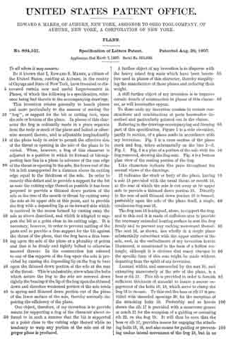
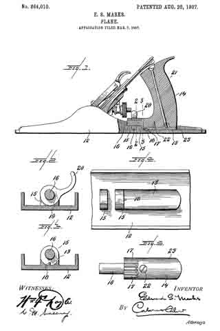
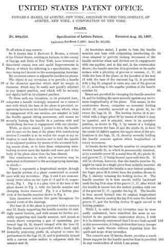
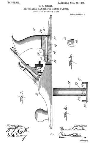
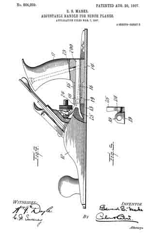
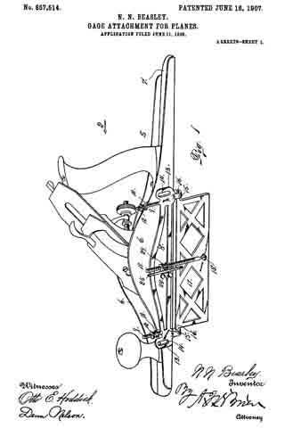
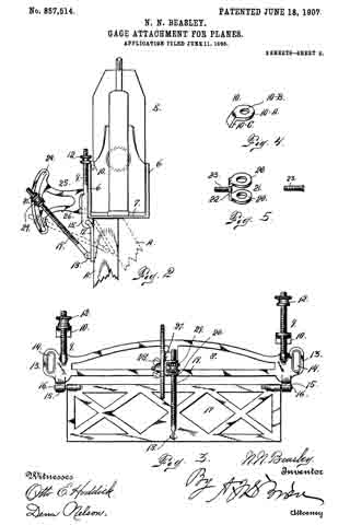
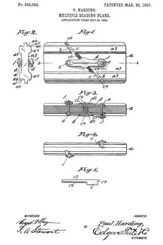
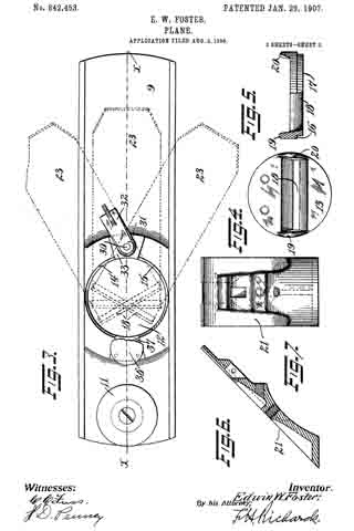
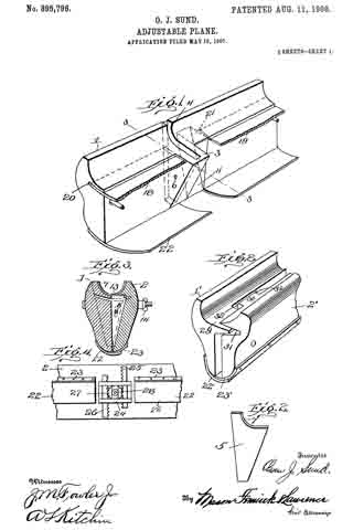
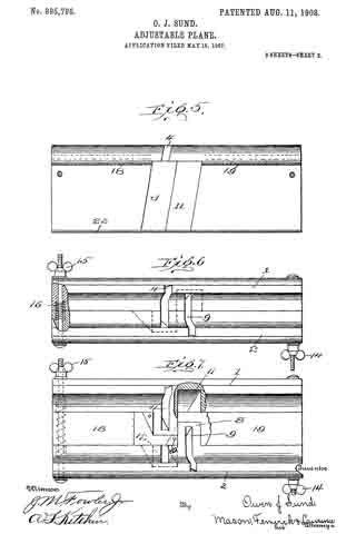
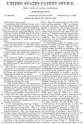
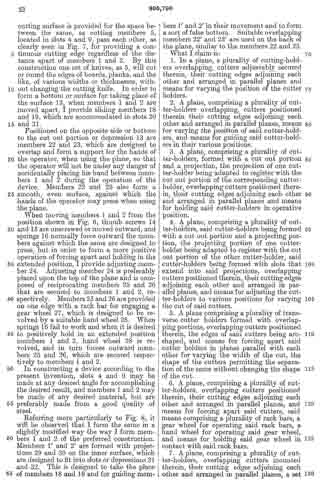
In the accompanying drawing:–Flgure 1 is a perspective view of one of the cutter-holders and surrounding parts. Fig. 2 is a side elevation of a cutter forming part of the present invention. Fig. 3 is a cross-section through a plane constructed according to the present invention the section being taken on the line 3–3 of Fig. 1. Fig. 4 is a detail fragmentary bottom plan view of a plane formed according to the present invention, an adjusting device being seen in connection therewith. Fig. 5 is a side elevation of one of the cutter-holding members. Fig. 6 is a bottom plan view of a plane formed according to the present invention the cutters being removed. Fig. 7 is a bottom plan view of a plane the cutters being removed, said plane being adjusted to its extreme position, certain parts being broken away to better disclose the invention. Fig. 3 is a detail fragmentary perspective view of a slightly modified form of the present invention.

In constructing a plane according to the present invention, I provide a pair of cutter-holding members 1 and 2. Member 1 has formed integral therewith an extension 3, as clearly seen in Fig. 1, for accommodating a slot 4, which is designed to extend from the outer edge of member 3 to the outer edge of member 1. Slot 4 is designed to be of such a shape and depth as to accommodate cutter 5. An adjusting screw or clamping member 6 is screw-threaded into member 3 and is designed to extend entirely through one of the walls of the same and engage cutter 5 for holding the same in position for having its cutting edge 7 project a short distance above the surface of the members 1 and 2. Member 2 is made similar to member 1 and has provided an extension 3 similar to extension 3 which is designed to accommodate a slot 9 similar to slot 4 in which a knife, as 5, is designed to be inserted and held in place by a suitable clamping member 10. Member 8 is designed to fit into a hollowed-out portion 11 in member 1 and member 3 is designed to iit into a hollowed-out portion 12 of member 2, when members 1 and 2 are in their closed position, as seen in Fig. 1, or when in a partially closed position. When in a closed position a semi-circular portion 13 is formed between members 1 and 2, as clearly seen in Fig. 3 for forming a rounded edge upon any board or other device that is designed to have the edges rounded. As seen in Fig. 3 the curved portion 13 is semi-circular in cross-section and the plane will cut or round the edge of any board or material to which the same is applied. If the material requires it the curved part 13 members 1 and 2 may be moved apart by unscrewing thumb screws 14 and 15. When thumb screws 14 and 15 are screwed outward, springs 16 will force outward member 22 to any desired distance, as, for instance, seen in Fig. 7. Though the members 1 and 2 are thus forced apart, a cutting surface is provided for the space between the same, as cutting members 5, located in slots 4 and 9, pass each other, as clearly seen in Fig. 7, for providing a continuous cutting edge regardless of the distance apart of members 1 and 2. By this construction one set of knives, as 5, will cut or round the edges of boards, planks, and the like, of various widths or thicknesses, without changing the cutting knife. In order to form a bottom or surface for taking place of the surface 13, when members 1 and 2 are moved apart, I provide sliding members 18 and 19, which are accommodated in slots 20 and 21.

Positioned on the opposite side or bottom to the cut out portion or depression 13 are members 22 and 23, which are designed to overlap and form a support for the hands of the operator, when using the plane, so that the operator will not be under any danger of accidentally placing his hand between members 1 and 2 during the operation of the device. Members 22 and 23 also form a smooth, even surface, against which the hands of the operator may press when using the plane.

When moving members 1 and 2 from the position shown in Fig. 6, thumb screws 14 and 15 are unscrewed or moved outward, and springs 16 normally force outward the members against which the same are designed to press, but in order to form a more positive operation of forcing apart and holding in the extended position, I provide adjusting member 24. Adjusting member 24 is preferably placed upon the top of the plane and is composed of reciprocating members 25 and 26 that are secured to members 1 and 2, respectively. Members 25 and 26 are provided on one edge with a rack bar for engaging a gear wheel 27, which is designed to be revolved by a suitable hand wheel 28. When springs 16 fail to work and when it is desired to positively hold in an extended position members 1 and 2, hand wheel 28 is revolved, and in turn forces outward members 25 and 26, which are secured respectively to members 1 and 2.

In constructing a device according to the present invention, slots 4 and 9 may be made at any desired angle for accomplishing the desired result, and members 1 and 2 may be made of any desired material, but are preflerably made from a good quality of steel.

Referring more particularly to Fig. 8, it will be observed that I form the same in a slightly modified way the way I form members 1 and 2 of the preferred construction. Members 1′ and 2′ are formed with projections 29 and 30 on the inner surface, which are designed to fit into slots or depressions 31 and 32. This is designed to take the place of members 18 and 19 and for guiding members 1′ and 2′ in their movement and to form a sort of false bottom. Suitable overlapping members 22′ and 23′ are used on the back of the plane, similar to the members 22 and 23.

What I claim is:

1. In a plane, a plurality of cutting-holders overlapping, cutters adjustably secured therein, their cutting edges adjoining each other and arranged in parallel lanes and means for varying the position of the cutter holders.

2. A plane, comprising a plurality of cutter-holders overlapping, cutters positioned therein their cutting edges adjoining each other and arranged in parallel planes, means for varying the position of said cutter-holders, and means for guiding said cutter-holders in their various positions.

3. A plane, com rising a plurality of cutter-holders, formed with a cut out portion and a projection, the projection of one cutter-holder being adapted to register with the cut out portion of the corresponding cutter-holder, overlapping cutters positioned therein, their cutting edges adjoining each other and arranged in parallel planes and means for holding said cutter-hollders in operative position.

4. A plane, comprising a plurality of cutter-holders, said cutter-holders being formed with a cut out portion and a projecting portion, the projecting portion of one cutter-holder being adapted to register with the cut out portion of the other cutter-holder, said cutter-holders being formed with slots that extend into said projections, overlapping cutters positioned therein, their cutting edges adjoining each other and arranged in parallel planes, and means for adjusting the cutter-holders to various positions for varying the cut of said cutters.

5. A plane comprising a plurality of transverse cutter holders formed with overlapping portions, overlapping cutters positioned therein, the edges of said cutters being arc-shaped, and means for forcing apart said cutter holders in planes parallel with each other for varying the widlfh of the cut, the shape of the cutters permitting the separation of the same without changing the shape of the cut.

6. A plane, comprising a plurality of cutter-holders, overlapping cutters positioned therein, their cutting edges adjoining each other and arranged in parallel planes, and means for forcing apart said cutters, said means comprising a plurality of rack bars, a gear wheel for operating said rack bars, a hand wheel for operating said gear wheel, and means for holding said gear wheel in contact with said rack bars.

7. A plane, comprising a plurality of cutter-holders, overlapping cutters mounted therein, their cutting edges adjoining each other and arranged in parallel planes, a set screw for holding the same in any desired position, and means for regulating the distance between said cutter-holding members.

8. A plane, comprising a plurality of cutter-holders, overlapping cutters positioned in said holders the edges of said cutters being segment shaped, means for varying the distance between said cutter-holding members, and longitudinal overlapping strips secured to said cutter-holding members on the edges opposite the cutting edges.

In testimony whereof I affix iny signature in presence of two witnesses.

OWEN J. SUND.

R. D. SHUTT,
W. G. HEINLY.

No. 890,575 – Plane (John L. Pringle) (1908)

[paiddownloads id=”655″]890575


UNITED STATES PATENT OFFICE.

_________________

JOHN L. PRINGLE, OF NEW BRITAIN, CONNECTICUT.

PLANE.

_________________

890,575. Specification of Letters Patent. Patented Jun. 9, 1908.
Application filed November 20, 1905. Serial No. 288,128.

_________________

To all whom it may concern:

Be it known that I, JOHN L. PRINGLE, a subject of the King of Great Britain, and residing at New Britain, in the county of Hartford and State of Connecticut, have invented a new and Improved Plane, of which the following is a specification.

My improvement relates to the class of hand tools used for working upon the surface of boards and the like for smoothing or for grooving, or for similar purposes, and the object of my invention is to provide a plane which shall be simple and cheap in construction, few as to the number of parts, and one which may be put to all of the varied uses to which this class of devices are subjected.

One form of device in the use of which the desired object may be attained is illustrated in the accompanying drawings, in which —

Figure 1 is a perspective view illustrating the bottom and one side of a plane embodying my invention. Fig. 2 is a like view looking from the opposite side of the plane. Fig. 3 is an end view showing the bottom gage-sole used as a side gage. Fig. 4 is what may be termed an illustrative view showing the application of my improvement in cutting a tongue on the edge of a board. Fig. 5 is a like view showing the improvement adapted to the formation of a molding. Fig. 6 is a like view showing the improved tool adapted to cut a groove in the edge of a board. Fig. 7 is a like view showing the improved tool as applied to cutting a concaved surface. Fig. 8 is a view illustrating a modified form of the adjustable gage-sole.

In the accompanying drawings the letter a denotes the body or stock of tlie plane, b a knob or handheld at the forward end, and c a handle located at or near the rear end and on the upper surface of the body part in the usual manner. The body part may be constructed of wood or of any other desired material common to tools of this class. The body part is also provided with a depthwise opening d in which the blade or bit e is located. All of these parts may be of any ordinary and well-known construction.

In carrying out my invention I provide a vertically adjustable secondary sole 1 secured preferably to the side part of the body of the plane, and a laterally adjustable gage-sole 2 which is located underneath the body. The sole 1 includes a plate extendin lengthwise of the body part of the plane, this plate being of proper width and thickness for the purposes in hand, and as shown herein, and as ears 4–5 projecting from the upper edge thereof. These ears are provided with slots 6 through which adjusting studs or screws 7 extend for the purpose of holding the plate in any position of vertical adjustment. An opening 8 is also formed through the ear 5 through which cutting tools or blades of various form may project.

The gage-sole 2 has slots 9 extending laterally thereof formed therein, and studs or screws 10 projecting through these slots into the body of the plane serve as a means of securing the shoe in any position of lateral adjustment. The heads of the screws 10 are located well within the slots, the latter being shouldered to receive the head of the screw. These slots 9 are located at equal distances from the ends of the sole so that the latter may be reversed end for end for certain purposes to be hereinafter described.

It will be seen from the above description and the accompanying illustration that by removing the soles 1 and 2 the plane may be used for all the purposes of a smoothing plane or other surfaces. By placing the secondary sole 1 in position and providing the proper cutting blade the plane may serve the purpose of a plow. By placing the gage-sole 2 and adjusting it in proper position laterally on the bottom of the body part with a proper shaped blade in position, the plane may be used to out moldings of different form. By properly adjusting the soles 1 and 2 with respect to each other and using a blade of proper form articles may be formed of curved shape or round.

The gage-sole 2 is provided on one edge with a recess 14 the walls of which are located preferably at right-angles to each other. When this groove is employed what may be termed the horizontally arranged wall 15 will serve as the bottom proper or sole of the plane, in connection, of course, with the secondary sole 1, and the side or vertically arranged wall 16 will form a gage.

The gage-sole 2 is provided with blade recesses 17 and 18. These recesses are formed to receive one side of the blade of a bit when the tool is used for certain purposes. As shown in Fig. 2, the recess 17 covers one side of the cutting edge of a comparatively wide bit, so that the pidane with such bit may be used as a fillister plane.

By adjusting the gage-sole 2 vertically and laterally, as shown in Fig. 5 of the drawings, and also by adjusting the second ary sole 1 it will be seen that the plane is readily adapted for cutting various forms of moldings, the blade 18 being, of course, properly adjusted.

By adjusting the parts as shown in Fig. 4 the device is adapted for cutting a tongue on the edge of a board, the bit 19 having one of the prongs lying within the opening 8 in the vertical guide, and the other prong extending through the shoulder 15, the edges of these being shown projecting as at 20 in Fig. 4. By reversing the gage-sole 2 and moving it to the position shown in Fig. 6 the device may be used for cutting a groove on the edge of a board, the same knife as shown in Fig. 4 being employed, and that point located within the opening in the secondary sole 1 cutting the groove and the other point being located within the recess 18 in the sole 2, as shown in dotted outline in Fig. 6.

If a circular or curved recess is to be reduced then a blade 21, as shown in Fig. 7 of the drawings, may be used, having its cutting edge of proper form, the extreme curved edge of the blade being located just in advance of the sole 1, and the sole 2 being emlployed as a guide.

In order to adapt the sole 2 for vertical adjustment adjusting supports are mounted on the arms 11, these consisting of a sleeve 22 having set screws 23 with wings 24 bearing adjusting screws 25 which engage threaded sockets in the surface of the gage-sole 2. When the gage-sole 2 is used with the recess 14 facing the secondary sole 1, as shown in Figs. 1, 2, 4, and 5 of the drawings, the screws 10 may be turned out of the stock a or may be removed entirely. It is also obvious that when the gage-sole 2 is used as shown in Figs. 1 and 2, the adjusting screws 25 are not absolutely essential, a though they form a means of support for the projecting edge of the sole.

While the secondary sole 1 has been shown herein as adjustable it is obvious that advantageous results would follow its use in a plane in which it was rigidly secured to the stock without any means of adjustment, but by providing the adjustment I secure all of the advantages present in the late as used in either of the ways mentioned.

In the form of adjustable sole shown in Figs. 1 and 2 the gage-sole is reversed end for end when it is desired to employ the sole as a gage. In Fig. 8 I have adapted this form of the invention so that the sole need not be so reversed when it is to be employed as a gage. In this form of the invention I construct the gage-sole in two parts, a main section 26 and an adjustable section 27. The main section is rovided with a groove 29, and the adjustable section with a shouldered groove 30, a screw 28 to take the place of the screws 10 hereinbefore described for holding the parts in engagement and for holding the sole as a whole in place on the sole or bottom of the plane. It will be seen from this construction that with the parts adjusted as shown in Fig. 8 the device is applicable for the same use as shown in Figs. 1 and 2. By loosening the screw and moving the adjustable section 27 so that the edges are flush, then the sole is adapted for a gage, as illustrated in Fig. 3. It will be noted that the parts 1 and 2 act as soles for the plane, that is, they support the plane in a direction depthwise thereof, the secondary sole 1 supporting the plane when grooves, tongues and the like are being cut, and the gage-sole in connection with the secondary sole supporting the plane as when moldings, and rabbets are cut. It will be noted that when either of the soles 1 and 2 are employed the sole proper of the plane is not in use, the latter mainly being employed when the plane is used as an ordinary surface plane.

I claim:

1. A stock having a bit opening and adapted for use as a surface plane, a secondary sole secured to the side surface of said stock and adjustable depthwise to project below the main sole thereof, and a gage-sole underlying said main sole and adjustable laterally thereof, both of said secondary and gage-soles having openings for the bit and adapted to cooperate therewith in the cutting operation.

2. A stock having a bit opening and adapted for use as a surface plane, a secondary sole secured to the side surface of said stock and adjustable depthwise to project below the sole thereof, a age-sole underlying the main sole and lateragy adjustable thereof, and means for securing the latter sole directly to the under surface of the stock, both of said secondary and gage-soles having openings for a bit to cooperate therewith in the cutting operation.

3. A stock having a bit opening adapted for use as a surface plane, a secondar sole secured to the side surface of the stock and adjustable depthwise to project below the main sole thereof, a reversible gage-sole underlying the said main sole, means for securing said sole in position, both of said secondary and gage-soles having bit openings to cooperate with the bit in the cutting operation.

4. A stock having a bit opening and adapted for use as a surface plane, a secondary sole secured to the side surface of the stock and adjustable depthwise to project below the main sole thereof, a reversible gage-sole underderlying said main sole and adjustable laterally thereof, means for securing said gage-sole directly to the bottom of the stock, both of said secondary and gage-soles having openings for a bit to cooperate therewith in the cutting operation.

5. A stock having a bit opening and adapted for use as a surface plane, a secondary sole secured to the side surface of the stock and adjustable depthwise thereof to project below its main sole, a gage-sole underlying the stock and adjustable vertically and laterally thereof, and means for adjustably securing said gage-sole directly to the under surface of the stock, both of said secondary and main soles having bit openings to cooperate therewith in the cutting operation.

6. A stock having a bit opening, and adapted for use as a surface plane, a secondary sole secured to the side surface thereof and adjustable depthwise to project below its main sole, a gage-sole underlying the stock and vertically and laterally adjustable thereof, means for adjustably securing said sole directly to the under surface of the stock and including slots for the reception of screws and recesses for the reception of the heads thereof, screws for securing said soles, each of said secondary and main soles having openings for a bit to cooperate therewith in the cutting operation.

7. A stock having a bit opening and adapted for use as a surface plane, a secondary sole secured directly to the side surface and adjustable deipthvvise to project below the main sole thereo, a reversible gage-sole underlying the stock and adjustable vertically and laterally thereof, and means for securing said sole directly to the main sole of the stock, both of said secondary and main soles having openings for the bit to cooperate therewith in the cutting operation.

8. A stock having a bit opening and adapted for use as a surface plane, a secondary sole secured to the side surface of the stock and adjustable depthwise to project below the main sole thereof, a gage-sole underlying the stock and reversible thereon and vertically and laterally adjustable thereof , slots in said sole for the reception of screws and recesses for the heads thereof, and screws for securing said sole directly to said main sole, both of said secondary and main soles having openings for a bit to cooperate therewith in the cutting operation.

JOHN L. PRINGLE.

Witnesses:
ARTHUR B. JENKINS,
LENA E. BERKOVITCH.

No. 890,519 – Joining-Plane (Wilfred R. Lansberry) (1908)

[paiddownloads id=”654″]890519


UNITED STATES PATENT OFFICE.

_________________

WILFRED R. LANSBERRY, OF DES MOINES, IOWA.

JOINING-PLANE.

_________________

890,519. Specification of Letters Patent. Patented June 9, 1908.
Application filed September 19, 1907. Serial No. 393,734.

_________________

To all whom it may concern:

Be it known that I, WILFRED R. LANSBERRY, a citizen of the United States, residing at Des Moines, in the county of Polk and State of lowa, have invented a certain new and useful Joining-Plane, of which the following is a specification.

The object of my invention is to provide a plane especially designed for use in trimming or cutting away the edge of a board on a line exactly parallel with the edge of another board placed adjacent to it, so that said boards may be fitted together accurately and smoothly, and my device is of special advantage in cases where neither of the boards to be fitted have perfectly smooth straight edges, and where it is necessary to do the work by hand.

My invention consists in the construction of the joining plane, whereby the objects contemplated are attained, as hereinafter more fully set forth, pointed out in my claims and illustrated in the accompanying drawings, in which —

Figure 1 shows a side elevation of a joining plane embodying my invention. Fig. 2 shows an enlarged sectional view on the line 2–2 of Fig. 1, also showing two boards in position to be operated on by the plane, one of said boards formed with a cut such as would be made by the plane. Fig. 3 shows a perspective view of the plane bit detached, and Fig. 4 shows a perspective view of the bolt for clamping the bit to the plane.

Referring to the accompanying drawings, I have used the reference numeral 10 to indicate the body of the plane, provided with a handle 11 at its rear, and a handle 12 at its front. Below the body 11 is a smooth, straight runner 13, cut away at 14 to receive the bit. A groove is formed on the body portion 10 to receive the bit, which groove inclines downwardly and forwardly, terminating in the cut-away portion 14, and it also inclines rearwardly and toward the left of the plane body relative to a transverse line through the plane. This latter inclination may be readily seen in Fig. 2. The plane bit comprises a straight, flat body portion 15 designed to enter the groove in the plane body, and a shank 16 narrower than the part 15, and having its right edge arranged substantially flush with the right edge of the runner so that it will not cut into a board at the right side of the runner. The left edge ofthe shank 16 is arranged with the forward corner 18 thereof projected a slight distance outside of the line of the left side of the runner, and the rear corner lies inside of said line. That is to say, the left side of the bit inclines rearwardly and toward the center of the runner, thus leaving a smoothing edge 18 at the forward corner thereof that projects beyond the runner, and that serves as a smoothing blade for the edge of a board at the left side of the runner against which it is to be moved. The lower end of the bit is sharpened in the ordinary way to cut a shaving from a board over which it is moved. I have used the reference numeral 17 to indicate the right edge of the bit, and 18 the forward corner of the left edge, which is the smoothing center.

I have provided for adjustably securing the bit to the body by means of a bolt 19, having a flattened portion at 20, which bolt is inserted in a suitable opening in the body 10 with its flattened surface engaging the bit body 15, a winged nut 21 being provided on the other end of said bolt. Formed on the right side of the runner 13, in front of the cut-away portion 14 is a vertical groove 22, with a central slot 23 therein. Mounted in said groove is a guide blade 24, and a set screw 25 extends through the blade and through the slot 23, whereby the blade may be set to any position of its adjustment. This guide blade is on the side opposite from the smoothing edge of the bit.

In Fig. 2 of the drawings, I h ave shown the adjacent edge portions of two boards, one of which is to be trimmed down so that it will fit accurately to the other. The board to be trimmed is indicated by the numeral 26. The other board serves as a guide, and is indicated by the numeral 27.

In practical use, I first place the two boards that are to be joined, together on a bench, with the edges that are to be joined adjacent to each other, and as nearly parallel as possible, it being assumed that the boards do not have perfectly straight edges. I then select the board that has the straightest edge and use it as the guide, and proceed to cut away the edge of the other board. I do this by placing the plane in position with the guide blade 24 against the edge of the board that is to be used as a guide while the cutting edge of the bit rests on top of the board that is to be cut away, near its edge. I then cut away one shaving throughout the entire length of the board to be trimmed and obviously the edge of the board that is formed by the cutting away of the first shaving, will be absolutely parallel with the edge of the guide board, I then continue the operation of cutting away one shaving at a time, until the guide blade projects below the board that is used as a guide. When the operation has proceeded. this far, the guide blade is not necessary, as the plane runner will be guided between the edge of the guide board and the edge of the board being cut that was formed by the removal of the shavings thus far made. Then the operator continues the removing of the shavings as before described. It is essential that the edge of the board first being cut be made comparatively smooth by the joining plane, for if it were left rough and uneven, then the edge would have to be smoothed with a smoothing plane, which might result in leaving it out of parallelism with the edge of the guide board, so that it is very essential that a smoothing edge be formed on the left side of the plane bit, which edge projects beyond the runner. It is also important that this smoothing edge be so arranged that it will not cut a shaving from the edge of the board, but it will smooth the edge by removing rough and uneven pieces left thereon by the successive cutting of shavings from said edge portion. Heretofore in dressing down the edge of a board, the plane bit has usually been placed against the edge to be cut. By the use of my improved plane, the bit is placed against the side of the board adjacent to the edge that is being trimmed, and the shavings are cut away successively until the board is entirely cut through from one side to the other. The guide board is firmly fixed in position throughout the entire operation so that when the board is cut through as before described, the resulting edge will be exactly parallel with the edge that was used as a guide, no matter how irregular the edge of the guide board may have been.

Having thus described my invention, what I claim and desire to secure by Letters Patent, is —

A joining plane comprising a straight runner formed with a bit recess, a guide blade adjustably mounted on one side of the runner in front of the bit recess, and abit adjustably mounted, having a sharpened lower edge, the front edge of the bit being inclined from a transverse line through the runner rearwardly, and to the left, the right edge of the bit being contained inside of the line of the right side of the runner, and the left edge of the bit having its forward corner projected outwardly beyond the runner to form a smoothing edge at the forward corner of said left side, and its left side inclined rearwardly and toward the center of the runner, the rear corner thereof being inside of the line of the left side of the runner.

Des Moines, Iowa, Aug. 21, 1907.

WILFRED R. LANSBERRY.

Witnesses:
RALPH ORWIG,
S. F. CHRISTY.

No. 879,793 – Plane (Andro Nyland) (1908)

[paiddownloads id=”653″]879793


UNITED STATES PATENT OFFICE.

_________________

ANDRO NYLUND, OF DULUTH, MINNESOTA.

PLANE.

_________________

879,793. Specification of Letters Patent. Patented Feb. 18, 1908.
Application filed May 28, 1907. Serial No. 376,047.

_________________

To all whom it may concern:

Be it known that I, ANDRO NYLUND, a citizen of the United States, and a resident of Duluth, in the county of St. Louis and State of Minnesota, have invented a new and Improved Plane, of which the following is a full, clear, and exact description.

This invention relates to planes, and it is particularly useful with rabbet or dado planes.

The object of the invention is to provide a simple, strong and efficient plane, having adjustable means for limiting the depth to which the cut of the plane may proceed, and which is provided with means for easily adjusting the plane iron and for locking the same in position.

A further object of the invention is to provide a plane having guide blades at both sides thereof, which can be easily and quickly adjusted, and which has means for limiting the projection of the blades.

The invention consists in the construction and combination of parts to be more particularly described hereinafter and fully set forth in the claims.

Reference is to be had to the accompanying drawings forming a part of this specification, in which similar characters of reference indicate corresponding parts in all the views, and in which Figure 1 is a side elevation of the plane; Fig. 2 is an elevation of the opposite side of the plane, showing parts broken away and in section 5 Fig. 3 is a vertical cross-section on the line 3–3 of Fig. 1; Fig. 4 is a vertical cross-section on the line 4–4 of Fig. 1; Fig. 5 is an enlarged view of a detail showing parts in cross section and parts broken away; and Fig. 6 is a plan view of a part of the plane.

Referring more particularly to the drawings, 1 represents the body of the plane, which may be of wood or any other suitable material. Secured to the body 1 is the sole-plate 2 extending the entire length of the tool. Side-plates 3 are secured to the sides of the body, and like the sole-plate 2 may be of steel or any other suitable material, preferably metal. The body 1 is cut away between the sides to form a plane iron recess 4. The recess 4 presents a flared opening 4a at the side, through which the shaving formed by the plane iron can leave the tool. The plane iron 5 is mounted in the recess 4 and presents a rack 6. A pinion 7 in mesh with the rack 6 is rotatably mounted in an extension 8 of the recess 4. The pinion 7 has a shank 9 extending through the side of the plate and provided with a wing 10, by means of which it may be operated. A locking-block 12 is secured upon the plane iron on the side opposite to the pinion 7. A set-screw 13 is mounted in a suitably threaded opening of the body and abuts against the block 12. The set-screw 13 is provided with a- wing 14 by means of which it may be operated to jam the plane iron in position through the block 12, which is carried in the recess 4 upon transverse pins 15 arranged in openings 16 of the block.

A recess 17 is formed in the body between the side plates 3, and connects with lateral guide grooves 18 formed at the sides of the body by the side-plates 3 which are cut away for this purpose. A threaded member 19 is arranged slidably in the recess 17 and is engaged by a screw pin 20. The screw pin 20 has a collar 21 seating against the upper part of the body, and a nut 22 in engagement with the inner wall of the recess to prevent the displacement of the screw pin, which has at its outer extremity a wing 23 by means of which it may be manually operated to adjust the member 19 within the recess. It will be understood that as the screw pin 20 is turned the member will move up or down within the recess. Guide blades 24 are slidably mounted in the guide grooves 18 and have slots 25. The guide blades 24 are adjustably secured to the member 19 by means of screws 26 arranged in the slots 25 and secured in suitable threaded openings in the member 19. The guide blades 24 have shoulders 27 adapted to engage with shoulders 28 formed at an edge of each slot, to limit the projection of the cutting point 29 of the blade from the groove. The guide blades are adapted to be projected a distance beyond the sole of the plane, equal at least to the projection of the plane eyes. In the operation of the plane in the usual manner, the guide blades form parallel grooves or guides exactly within and between which the plane iron follows and cuts the shaving.

A vertical guide-way 30 is formed within the body and has a lateral slot 31 extending through the side 3. A slidable member 32 comprising substantially a rod, is arranged within the guide-way 30 and has a lateral extension 33 in the slot 31. A gage member is secured to the extension 33 by means of a screw 35. The gage member 34 has a supplemental sole 36. The gage member may be adjusted at the side of the body by moving the member 32 up or down within the guide-way. A transverse pin 37 is arranged adjacent to the member 32 and has a wing 33 at the side, by means of which it may be operated. An eccentric cam groove 39 is formed in the pin 37. When the member 32 engages the cam groove at the greatest depth of the same the member is free to slide within the guide-way. When the pin 37 is rotated from this position the member 32 is jammed within the guide-way by the cam-like action of the groove. The pin 37 is provided with a second annular groove 40 with which a pin 41 carried by the body engages to prevent the lateral displacement of the adjusting pin 37. Aleaf spring 47 is arranged in the guide-way 30 and engages the member 32 to hold the same resiliently within the guide-way and to prevent lateral movement of the same. The gage 34 serves to determine and measure the depth oi the rabbet formed by the plane. A guide-plate 42 having slots 43 is adjustably mounted at the side of the plane opposite to the gage 34, by means of set-screws 44 arranged in the slots 43 and in suitable openings of the body. The guide-plate 42 extends the entire length of the plane and is adapted to be projected below the sole of the same to guide the tool at the edge of the work when a rabbet is being cut. A handle 45 is mounted by means of screws 46 at one side of the plane and serves for holding the tool when it is in operation.

Having thus described my invention I claim as new, and desire to secure by Letters Patent:

1. In a plane, a plane iron having a rack, and a pinion adapted to be manually controlled and operatively engaging with said rack, a block tapered toward the cutting edge of said iron and loosely mounted to engage the same, and a set screw adjustably engaging said block to lock said iron in position.

2. In a plane, a body having a guide-groove, a guide-blade mounted to slide in said groove, a movable member arranged to slide in the longitudinal direction of said groove and having an adjustable connection with said blade, and means for adjusting said member.

3. In a plane, a body having a recess, and a guide-groove communicating with said recess, a movable member in said recess, a guide-blade in said groove and having an adjustable connection with said member, and a screw-pin engaging with said member and controlling the same.

4. In a plane, a body having a recess, and a guide-groove communicating with said recess and presenting a shoulder, a movable member in said recess, a guide-blade in said groove and having an adjustable connection with said member, said guide-blade presenting a shoulder adapted to engage said shoulder of said guide-groove to limit the projection of said blade from said groove, and a screw-pin engaging with said member and controlling the same.

5. In a plane, a body having a recess and guide-grooves at opposite sides of said body and communicating with said recess, a movable member in said recess, guide-blades in said grooves and presenting slots, adjustable screws carried by said member and engaging said slots to secure said blades to said member, and a screw-pin operatively engaging said member and having collars engaging said body to prevent the longitudinal movement of said pin.

In testimony whereof I have signed my name to this specification in the presence of two subscribing witnesses.

ANDRO NYLUND.

Witnesses:
S. C. MILLER,
W. A. ANDERSON.

No. 876,789 – Scraper (William Erdmann) (1908)

[paiddownloads id=”652″]876789


UNITED STATES PATENT OFFICE.

_________________

WILLIAM ERDMANN, OF MADISON, WISCONSIN.

SCRAPER.

_________________

876,789. Specification of Letters Patent. Patented Jan. 14, 1908.
Application filed August 28, 1907. Serial No. 390,520.

_________________

To all whom it may concern:

Be it known that I, WILLIAM ERDMANN, residing at Madison, in the county of Dane and State of Wisconsin, have invented a new and Improved Scraper, of which the following is a specification.

My invention relates to certain new and useful improvernents in scrapers for dressing floors and the like, and the invention primarily has for its object to provide a scraper of an improved construction which can be easily and cheaply manufactured and which will readily and effectively serve its intended purposes. In my invention means are provided for holding and clamping the scraping blade, which means can be easily and quickly adjusted to permit insertion or withdrawal of the blade, as the case may be.

Another object of my invention is to provide a scraper having a yielding pad against which the blade rests to absorb or prevent vibration when the implement is in use.

The invention also embodies certain novel construction, combination and arrangement of parts, all of which will be first described in detail and then be specifically pointed out in the appended claims, reference being had to the accompanying drawings, in which, —

Figure 1, is a perspective view of my invention. Fig. 2, is a central, vertical section thereof. Fig. 3, is a horizontal section on the line 3–3 of Fig. 2. Fig. 4, is a perspective view of the metallic gage and blade holding clamp member. Fig. 5, is a similar view of the stock and handle member. Fig. 6, is a perspective view of the bridge members.

Referring now to the accompanying drawings in which like letters and numerals of reference indicate like parts in all of the figures, 1 designates the stock with which the handles 1a merge, and the stock 1 has its under face plane, while its front face 1c is in a plane held at an obtuse angle to the plane containing the horizontal surfaces 1b of the stock.

Cemented or otherwise held in contact with the front face 1c of the stock 1, is a pad 2, of leather or other similar yielding material of substantially even thickness throughout, and against which the scraping blade 3 is held.

The blade 3 may be of the ordinary type and have the usual cutting edge 3a, as shown.

On the rear the stock 1 is formed with an elongated countersunk portion 1d to receive the bow shaped bridge member 4 and the set screw carrying bridge bar 5, the bar 5 having a threaded aperture to receive the set screw 6 and having its ends cut away as at 5b to form nut holding sockets.

The ends of the bars 4 and 5 have alining apertures 4a and 5a which register with the bolt holes 1x in the stock 1, to permit passage of the clamping bolts 7 which cooperate with the nuts 8, as shown.

9 designates the combined gage and blade holding clamp member which has the usual body 9a whose under face 9b lies in the same plane with that containing the face 1b of the stock 1. The body 9a has an upwardly projecting rear face 9c held at an acute angle to the face 9b and it also has upwardly projecting arms 9c having depressed blade receiving portions 9d and bolt apertures 9e together with a clearance space 9f to permit passage for the shavings.

In practice, the parts are arranged as shown in Figs. 1, 2 and 3. To loosen the member 9 and release the blade, it is only necessary to turn the set screw to ease up on the tension exerted on the bolt, when the blade may be easily withdrawn for sharpening or otherwise. When it is desired to reinsert the blade it is only necessary to replace the same in the position shown in Fig. 1, within the recesses 9d and tighten up on the set screw, thus exerting a tension on the bolts and drawing the member 9 against the blade, and tightly clamping the blade against the yieldable cushion or pad.

By constructing a scraper as shown and described, the same can be easily and cheaply manufactured at a minimum expense and the blade can be readily adjusted to its proper position as well as easily and quickly removed for sharpening, the provision of the yieldable pads serving to take up any vibrations which may occur during the operation of the implement and prevent chattering of the blade.

It will be noticed that the cut away ends of the set screw carrying bridge member 5 together with the countersunk portion of the stock 1 in which the bridge members are held, serve as a nut lock and prevent the nuts becoming loose, it being understood that the heads 7a of the bolts have their faces held at a slight angle to the longitudinal axis of the bolts, thus preventing turning of the bolt when the set screw is tightened up.

From the foregoing description, taken in connection with the accompanying drawings, it is thought the complete construction, opoperation and numerous advantages of my invention will be readily understood by those skilled in the art to which the invention appertains.

What I claim is, —

1. The combination with the stock, the blade holding clamp member, and means for mounting the blade holding clamp member on the stock, of means carried by the stock and cooperatively connected with the aforesaid mounting means for causing the blade carrying clamp member to clamp the blade against the stock substantially as shown and described.

2. The combination with the stock, the blade holding clamp member having blade receiving recesses and the blade therein, of securing means passed through the clamping member and the stock for holding the clamping member to the stock, and means for tightening up or loosening said securing means to clamp or release the blade, substantially as shown and described.

3. The combination with the stock, the blade holding clamp member having blade receiving recesses and the blade therein, of securing means passed through the clamping member and the stock for holding the clamping member to the stock, means for tightening up or loosening said securing means to clamp or release the blade, said last named means comprising a pair of bridge members carried by the stock and cooperatively connected with the securing means, and means carried by one of said bridge members for exerting a tension on said securing means to draw the blade holding clamp member tightly against the blade, substantially as shown and described.

4. The combination with the stock, the blade holding clamp member having blade receiving recesses and the blade therein, of securing means passed through the clamping member and the stock for holding the clamping member to the stock, means for tightening up or loosening said securing means to clamp or release the blade, said last named means comprising a pair of bridge members carried by the stock and cooperatively connected with the securing means, means carried by one of said bridge members for exerting a tension on said securing means to draw the blade holding clamp member tightly against the blade, and a yieldable pad interposed between the blade and the blade holding clamp member and the stock, substantially as shown and described.

5. The combination with the stock, the blade holding clamp member and the blade, and bolts for securing the blade holding member to the stock, of tension devices for said bolts to cooperate with the blade holding clamp members, substantially as shown and described.

6. The combination with the stock, the blade holding clamp member and the blade, and bolts for securing the blade holding member to the stock, of tension devices for said bolts to cooperate with the blade holding clamp members, said tension devices comprising a bridge member connected with said bolts, and means cooperating with the bridge member for exerting a tension on said bolts.

7. The combination with the stock, the blade holding clamp member and the blade, and bolts for securing the blade holding member to the stock, of tension devices for said bolts to cooperate with the blade holding clamp members, said tension devices comprising a bridge member connected with said bolts, means cooperating with the bridge member for exerting a tension on said bolts, said last named means comprising a set screw passing through said bridge member, substantially as shown and described.

8. The combination with the stock, the blade holding clamp member and the blade, and bolts for securing the blade holding member to the stock, of tension devices for said bolts to cooperate with the blade holding members, said tension devices comprising a bridge member connected with said bolts, means cooperating with the bridge member for exerting a tension on said bolts, said last named means comprising a set screw passing through said bridge member, and a supplemental bridge member held within said stock and adapted to be cooperatively engaged by said set screw, substantially as shown and described.

WILLIAM ERDMANN.

Witnesses:
ERNST SAABER,
REINHOLD MATHWIG.

No. 871,001 – Bench-Plane (Ernest W. Smith) (1907)

[paiddownloads id=”651″]871001


UNITED STATES PATENT OFFICE.

_________________

ERNEST W. SMITH, OF GRAND MARAIS, MICHIGAN.

BENCH-PLANE.

_________________

871,001. Specification of Letters Patent. Patented Nov. 12, 1907.
Application filed July 5, 1907. Serial No. 382,245.

_________________

To all whom it may concern:

Be it known that I, ERNEST W. SMITH, a citizen of the United States, residing at Grand Marais, in the county of Alger and State of Michigan, have invented certain new and useful Improvements in Bench-Planes, of which the following is a specification.

This invention is a bench plane, and has for its object an improved bit-adjustment by means of which a lateral, as well as longitudinal, adjustment of the bit is had.

In the accompanying drawings, Figure 1 is a side elevation of the invention. Fig. 2 is a longitudinal section. Fig. 3 is a transverse section on the line 3–3 of Fig. 1. Fig. 4 is a plan view of a portion of the bit-stock with the bit and adjusting means removed. Fig. 5 is a perspective view of the various parts constituting the invention showing them separated.

Referring specifically to the drawings, 10 denotes the stock of the plane having at its rear end the usual handle 11 and at its front end a knob 12. The bit 13 projects through the throat 14 in the sole 15 of the stock as usual. The handle 11 is secured to the stock by a clamping screw 16 which passes through the handle and into a frog 17 on the stock, the lower end of the handle being recessed to receive the frog. The knob 12 is fastened to the stock in a similar manner.

Adjacent the throat 14 is a frog 18 to which the bit and its adjusting means are attached. Near the top of the frog is a recess 19 in which a frame 20 is pivotally mounted on a screw 21 passing through the frame and into the frog. The lower end of the recess 19 is undercut as indicated at 22 to receive a rib 23 on the lower end of the frame which is for the purpose of guiding the movement of the latter. In the back of the frame near its lower end is a recess 24 from which an opening 25 extends through the frame. In the recess is seated a worm-wheel 26 having a hub 27 which passes through the opening 25, and above the frame 20 the hub is toothed as indicated at 28 to form a pinion. The hub and worm-wheel are formed in one piece and are mounted on a screw 29, the head 30 of which is spaced from the pinion 28 with a sleeve 31 and a washer 32 on the screw between said parts. The worm-wheel and hub are made fast to the screw by a small set-screw 33. Between the wall of the recess 24 and the top of the worm-wheel 26, is a ball-bearing 34. On one side of the frame 20 is a boss 35 having a bearing for the shaft of a worm 36 which meshes with the worm-wheel 26.

The bit 13 is supported on top of the frame 20, and below the same on the frog 18, and has a longitudinal slot 37 in which the pinion 28 works. On one side of the slot is a rack 38 which is in mesh with the pinion, by means of which longitudinal adjustment of the bit is had. The pinion is rotated through the worm-gearing therein described. The worm shaft is fitted with a knurled knob 39 for turning it.

The cap 40 for clamping the bit in adjusted position has a slot 41 provided with a rabbet 42. This slot receives the sleeve 31, and the head 30 of the screw 29 engages the rabbet, the washer 32 being placed therebetween. The sleeve is loose on the screw and thus serves as an antifriction roller. Near one end of the slot, the rabbet is discontinued whereby an enlargement is had to permit the removal of the cap. The cap is clamped to the bit by a cam 43 which has antifriction rollers 44.

Upon releasing the cap by disengaging the cam 43, the bit can be adjusted laterally to line its cutting edge with the sole of the stock by swinging the frame 20 on its pivot 21, and for this purpose the upper end of the frame has an extension or finger piece 45. When the frame is swung as stated the bit swings in the opposite direction by reason of the relative location of the hub 27 and the pivot 21. The cap 40 swings with the bit, and after the desired adjustment is made the bit will be clamped by the cap in the ordinary manner.

The parts herein described securely hold the bit at adjustment and it cannot slip back when striking a knot or other hard substance. Friction is minimized, and the parts are easily operated. The location of the knob 39 is such that it can be operated by the thumb and forefinger without removing the hand from the handle 11.

I claim:–

1. A plane comprising a stock, a frog adjacent the throat thercof, a bit-carrying frame pivoted on the frog, a worm-wheel mounted in the frame and having a toothed hub, a worm and its shaft mounted in the frame, means for turning the worm-shaft, a bit having a longitudinal slot provided with a rack meshing with the toothed hub, a slotted cap on the bit, a screw extending from the aforesaid hub and having its head seating in the slot ot the cap, and clamping means for the cap.

2. A plane comprising a stock, a frog adjacent the throat thereof provided with an undercut recess, a bit-carrying frame pivoted on the frog and having a guide-rib extending into the undercut portion of the aforesaid recess, and means for clamping the bit to the frame.

In testimony whereof I affix my signature, in presence of two witnesses.

ERNEST W. SMITH.

Witnesses:
COLIN D. DOIG,
WILLIAM VION.

No. 869,267 – Plane (John H. Shaw) (1907)

[paiddownloads id=”650″]869267


UNITED STATES PATENT OFFICE.

_________________

JOHN H. SHAW, OF NEW HAVEN, CONNECTICUT, ASSIGNOR TO SARGENT & COMPANY, OF NEW HAVEN, CONNECTICUT, A CORPORATION OF CONNECTICUT.

PLANE.

_________________

869,267. Specification of Letters Patent. Patented Oct. 29, 1907.
Application filed August 10, 1905. Serial No. 273,590.

_________________

To all whom it may concern:

Be it known that I, JOHN H. SHAW, of the city and county of New Haven, State of Connecticut, have invented new and useful Improvements in Planes, of which the following is a full, clear, and exact description, when taken in connection with the accompanying drawings, which form a part thereof, and in which —

Figure 1 represents a side elevation of a plane embodying the invention, Fig. 2 an end view of the same, Fig. 3 a similar view with the handle shown adjusted to a different position, Fig. 4 a top view of the handle end of the plane, Fig. 5 a similar view with the handle removed, Fig. 6 a similar view with the supporting block removed, Fig. 7 a bottom view of the handle plate, and Fig. 8 a side elevation of the supporting block.

In all figures, similar letters of reference represent like parts.

This invention relates to planes, and has for its object the production of a simple and efiicient construction by which the handle may be adjusted so that the plane can be used close to a wall or other object without injury to the hand of the operator.

When a plane is used in proximity to an object, as a wall, it is diflicult to bring the plane close to the corner without interfering with the hand of the operator. To this end various methods have been devised by which the handle may be adjusted or turned to an angle other than a right angle to the bottom of the plane so as to remove the hand of the operator further from the side of the plane against the wall.

The present invention consists of a removable supporting block for the handle, which may be mounted on the ordinary plane body so that the handle may be adjusted or rotated on the supporting block to project at the desired angle, together with other improvements and combinations of parts hereinafter described and claimed.

For a better understanding of the invention reference is had to the accompanying drawings, in which the parts designated by the letter A represent the plane body and B the sides thereof. On the plane body, near the rear, is a usual base C for the handle, having a screw hole or holes D. When a handle is mounted on this base it assumes the ordinary position at right angles to the plane body, and is incapable of adjustment.

A supporting block E is therefore provided, which is herein shown fiat on its under side and convex transversely on its upper face (Figs. 2 and 3). The supporting block E is adapted to be secured to the plane body by a screw F, or other means, taking into one of the screw holes D.

The handle G is provided at its lower end with a plate H concaved transversely as shown, so that its under face is adapted to fit on the convex surface of the supporting block E. The plate is provided with one or more transverse slots K for the reception of screws L, which extend through the slots and take into screw holes M in the block E. The heads of the screws L or washers N, engaged thereby, bear on the plate H to bind in its adjusted position.

To shift the handle from one angle with the plane body to another it is only necessary to unscrew the screws L and the plate H will then be capable of sliding in either direction on the block E, so that the handle will assume either of the positions indicated in Figs. 2 or 3. When the screws L are tightened the handle is secured to its adjusted position. As the block E is removable the plane body may be used with an adjustable handle or with an ordinary handle as desired.

Having now described my invention, what I claim and desire to secure by Letters Patent is:

In a plane, the combination with the plane body; of a removable supporting block curved in cross section and adapted to be rigidly secured to the plane body; a correspondingly curved plate adapted to fit on said supporting block; a handle secured to said plate; slots in said plate; and screws projecting through said slots and engaging said block to hold said plate and handle in their adjusted position, substantially as described.

In witness whereof, I have hereunto set my hand on the 4th day of August, 1905.

JOHN H. SHAW.

Witnesses:
W. A. RICE,
L. F. BREESE.

No. 869,016 – Extension-Plane (John V. Petrusich) (1907)

[paiddownloads id=”649″]869016


UNITED STATES PATENT OFFICE.

_________________

JOHN V. PETRUSICH, OF CHICAGO, ILLINOIS.

EXTENSION-PLANE.

_________________

869,016. Specification of Letters Patent. Patented Oct. 22, 1907.
Application filed June 17, 1907. Serial No. 379,311.

_________________

To all whom it may concern:

Be it known that I, JOHN V. PETRUSICH, a citizen of the United States, residing at Chicago, in the county of Cook and State of Illinois, have invented a new and useful Extension-Plane, of which the following is a specification.

This invention relates to improvements in planes.

It is well known that carpenters and others using this class of tool find occasion to use several sizes of the same and the object of this invention is to provide what may be termed an extension plane or a plane in which the several essential sizes of the tool are combined in one.

With this and other objects in view the invention consists in the construction and combination of parts to be hereinafter described, pointed out and claimed in the following specification and illustrated in the accompanying drawings, in which:–

Figure 1 is a side elevation of the device complete. Fig. 2 is a detail of a slotted bar and pin therefor used for locking the extension members. Fig. 3 is a view similar to Fig. 1 showing in dotted lines the position of the extension members when the plane is closed. Fig. 4 is an end of the device partly in section and taken on line d–d Fig. 9. Fig. 5 is a view in section of Fig. 4 taken on line a–a. Fig. 6 is a detail perspective of the rack employed in the extension portion of the device. Fig. 7 is a plan view of the plane closed. Fig. 8 is a front view of Fig. 7, partly in section, and taken on the line b–b. Fig. 9 is a section taken on line c–c of Fig. 7.

Like reference characters indicate corresponding parts throughout the several views.

The reference numeral 2 represents a plane of ordinary or preferred construction having longitudinal sockets 2a opening in either extremity of the side walls 2b of the plane and running horizontally and parallel with each other as shown in Fig. 3.

The numeral 3 represents extension rods adapted to fit slidably into the sockets 2a and having graduations 4 on their lateral surfaces for measuring off the work. Roller-carriers 7 are provided at the external extremities of the extension rods as shown in section in Fig. 4 and as shown complete in Fig. 1, in which are pivoted the rollers 8 for the purpose of carrying the plane smoothly over the work. A brace 6 connects either pair of roller-carriers as shown in Fig. 7 for the purpose of holding the extension rods rigidly parallel.

Either roller-carrier arranged on either left-hand extension rod is recessed on the surface adjacent the roller so that it may carry a rack 10 provided with a slot 11 which engages the pivot of the roller 8. Each left-hand roller-carrier is fiuther provided with a worm 9 which engages the rack 10 for the purpose of raising and lowering the same as shown in detail in Figs. 4 and 5. When the rack 10 is dropped below the lelt-hand edge of the work it serves as a lateral drop guide to keep the plane flush with that edge of the work as shown in Fig. 1.

12 represents a knob of the plane provided with a screw 13 running the entire length of the same and protruding beyond the lower extremity thereof.

14 represents the upper section of a clamp slidably arranged on the extension rods and provided with a threaded aperture to receive the screw 13 protruding from the knob 12 which is seated on said portion of the clamp.

14a is the lower section of the clamp arranged on the extension rods in a manner similar to the upper portion and provided with a threaded aperture to receive the screw 13 that extends through the upper portion of the clamp. By turning the knob 12 to the right the sections of the clamp 14 and 14a are drawn together and are caused to grip the extension rods firmly thus affording rigid handles to the plane.

15–15 represents a pair of slotted bars arranged on the side walls of the plane by means of the screws 16 movable with said bars. The screws 16 extend vertically through the side walls of the plane to the sockets 2a and when the slotted bars are turned at right angles with the side walls of the plane the screws 16 engage the extension rods resting within the said sockets and hold them firmly.

17 represents a horizontal connecting link pivoted at 18 and engaging the slotted bars 15 in the manner shown in Fig. 7. By turning this horizontal link until it lies in a straight angle with the two slotted bars it will cause the screws 16 to engage the extension rods as above described. Thus it will be seen, the extension rods can be partly withdrawn from their sockets and locked in that position.

Either end of the plane is provided with similar extension apparatus and hence a description of that on one end is a description of the apparatus on the other.

Having fully described my invention, what I wish to claim and secure by Letters Patent of the United States is:

1. In a plane, extension means journaled in the side walls thereof, a sliding clamp mounted on said extension means, a knob seated on said sliding clamp and supporting means terminally carried by said extension means substantially as described.

2. In a plane, extension means journaled in the side walls thereof, an extension stop carried on the side walls thereof, a sliding clamp mounted on said extension means, a knob seated on said sliding clamp, roller-carriers terminally arranged on said extension means, a roller pivoted within said roller-carriers and a lateral drop guide carried by said roller-carrier substantially as described.

3. In Combination with a plane having longitudinal sockets in the side walls thereof, sliding extension rods arranged therein, a. sliding screw-actuated clamp arranged on said extension rods, a knob seated on said clamp by which the same may be anchored or released, roller-carriers terminally carried by said extension rods, a roller pivotally carried by said roller carriers, a brace 6 connecting said roller-carriers and a worm and rack carried by said roller-carriers substantially as described.

In testimony that I claim the foregoing as my own, I have hereto affixed my signature in the presence of two witnesses.

JOHN V. PETRUSICH.

Witnesses:
ROSE GREENBERG,
FREDERICK RINDLER.

No. 868,803 – Beading Or Molding Tool (Alphonse Pellrin) (1907)

[paiddownloads id=”648″]868803


UNITED STATES PATENT OFFICE.

_________________

ALPHONSE PELLRIN, OF DETROIT, MICHIGAN.

BEADING OR MOLDING TOOL.

_________________

868,803. Specification of Letters Patent. Patented Oct. 22, 1907.
Application filed January 28, 1905. Serial No. 243,162.

_________________

To all whom it may concern:

Be it known that I, ALPHONSE PELLRIN, a citizen of the United States of America, residing at Detroit, in the county of Wayne and State of Michigan, have invented certain new and useful Improvements in Beading or Molding Tools, of which the following is a specification, reference being had therein to the accompanying drawings.

This invention relates to improvements in beading or molding tools, and its object is to provide a simple, cheap and efficient device so constructed that the cutting bit or blade may be rotated or turned to advance one end of the lower or cutting edge ot the bit along the line of its travel to give the same a shearing cut, and also to provide simple means for adjustably holding the bit which may be readily attached or detached.

A further object of the invention is to provide the same with a detachable sole plate and with certain other new and useful features, all as hereinafter more fully described, reference being had to the accompanying drawings, in which

Figure 1, is a front edge elevation of a device embodying the invention and showing the same partly in longitudinal section; Fig. 2, is an inverted plan view ot the stock with all detachable parts removed; Fig. 3, is a side elevation of one of the knife or bit holders, detached; Fig. 4, is a perspective view of one of the sole plates, detached; Fig. 5, is an end view of the device with the handle broken away; and Fig. 6, is an enlarged perspective view of one end of the device showing the same in transverse section through the center of one ol the bit holders.

As shown in the drawing 1 is the stock of the tool consisting of a flat bar which is formed with a handle 2 at each end and with two circular openings 3, one near each end of the flat bar or stock, to receive the bit holders 4, each consisting of a casting formed with an upwardly extending inclined bed 5 for the knife or bit 6, and with a downwardly extending ring-shaped flange 7 to fit the circular opening 3 in the stock. The ring 7 is provided with an outwardly extending circular flange 8 to engage the upper surface of the stock and the holder is adjustably secured in the opening by providing an elongated slot 9 in said flange 8 to receive a screw 10 extending throughout and engaging a screw-threaded opening in the stock. Extending forward from the bed 5 at each side of the bit is the side flange 11, each of which is provided with a notch 12 extending downward from its upper end to receive laterally extending arms 13 on the clamping plate 14 which is provided with a screw-threaded opening near its upper end to receive a clamping thumb screw 15 adapted to extend through said opening and engage the bit, thus rocking said plate on its arms and causing the lower end thereof to press upon the bit and clamp the same firmly to its bed.

The lower end or cutting edge ot the bit 6 is shaped to give the article worked upon the desired form and a sole or wear plate 16 formed on its lower face to conform to the configuration of said cutting edge, is secured to the under surface of the stock over each opening 3 by providing said plate 16 with upwardly extending lugs 17 at one end, forming a dovetail opening between them to receive a dovetail rib 18 on the adjacent end of the stock, beneath the handle, and to further secure each sole plate in place, a screw 19 is provided. An opening 20 in said sole plate is provided for the end of the bit, through which it extends and which is of a size to permit the shavings to pass.

A longitudinal slot 21 is formed in the stock between the openings 3 and the lower face of the stock is cut away adjacent to said slot to term a longitudinal groove 22 to receive the stops 23 adapted to be adjusted along said groove and held therein by screws extending through the slot. These stops are provided to engage the edge of the board or other article being grooved or formed and cause the groove to be formed at the desired distance from the edge thereof.

For convenience the tool is provided with two bits or cutters but it is obvious that only one may be employed and by the particular construction of clamping plate but one screw is necessary and the plate and bit may be quickly removed by simply loosening the thumb screw.

By loosening the screws 10, the holders 4 may be turned within the openings 3 to set the blades or bits at an angle to the longitudinal axis of the stock or bar 1, so that one end of the cutting edge of each will cut in advance of the other end thereof and thus have a shearing action and so that the ends of said cutting edges may be moved nearer or farther from each other, thereby permitting line adjustment of the distance between the outer lines of the cut to be made.

Having thus fully described the invention what I claim is:

1. A routing tool comprising a stock adapted to be moved laterally across the work, a pair of bit holders each secured near one end of the stock, rotatable on an axis vertical to the plane of the stock, and each provided with a bit throat, a bit bed, a bit clamping plate and a bit having a cutting edge whose outer end projects beyond the body of the edge, so disposed that limited relative adjustment of the stock is obtained by the rotation of the bit holders, a guide slot between the bit holders in their axial plane, a gage plate for each bit holder adjustably secured in the slot, and a sole platefor each bit detachably interlocked with the stock outside of each bit holder, extending over and in register with the throat of the holder.

2. A routing tool comprising a narrow, substantially rectangular stock, adapted to be laterally moved across the work, handles on each end of the stock, integral therewith, a pair of bit holders, each consisting of a cylindrical base rotatably secured near one end of the stock vertically to the face of the stock, with its lower face flush with the stock face, means for clamping the holders in any desired angular relation to the stock, comprising a peripheral flange on the base, bearing on the upper side of the stock, a segmental slot in the flange, and a stud screw clamping the flange to the stock, passing through said slot, oblique means for securing a bit in each holder consisting of a bit bed extending obliquely up from the base, marginal, longitudinal flanges on the bed, longitudinally disposed grooves in the upper end portions of the flanges, a bit clamping plate provided with integral, alined lateral lugs between its ends, rocking and sliding in said grooves, and a thumb screw in the upper part of the clamping plate above the lugs, substantially perpendicular to the bed, means for centering the bit holders in relation to a neutral zone, consisting of a longitudinal slot in the stock between the bit holders in axial alinement therewith, whose margins in the stock bed are rabbeted to form a guide, gage plates for the bit holders, each provided with a longitudinal rib engaging the guide, adapted to center the bits in relation to a neutral surface between them, means for shielding bits in the holder comprising soles for each bit holder, each comprising a plate having an opening whose margins register substantially with the working edge of a bit, detachably held in alinement with a bit holder by a rib integrally fortned on the underside of the adjacent handle shank, adapted to dovetail with a lug integral with the plate, and a screw clamping the plate to the stock face over the bit holder.

3. A routing tool comprising a stock having a rectangular plane bed, handles integrally formed at each end thereof, a pair of bit holders in parallel spaced relation, each comprising a cylinder whose axis is perpendicular to the stock bed, each rotatably secured in an aperture in the bed near one end thereof, with their lower end faces flush with the bed, an annular flange on the upper end of each cylinder bearing on the upper side of the stock, a segmental slot in each flange, a screw passing through the slot, secured in the bed, a diametrically disposed throat opening in each cylinder, a lug extending obliquely from each cylinder, whose upper face is longitudinally grooved for a bit bed, a bit clamping plate, tiltably secured over each bed by integral, lateral lugs between the ends of the plate, sliding and rocking in parallel, longitudinal grooves in the side faces of the bed groove, a clamping thumb screw for each plate engaging a screw-threaded aperture in the upper end beyond the lugs, longitudinal, alined, undercut ribs on the under sides of the handle shanks, a shoe for each bit holder, provided with a lug adapted to detachably engage the adjacent undercut rib, and a countersunk screw engaging the stock, a longitudinal, rabbeted slot between the holders in their axial plane, an angle gage plate for each bit holder engaging said rabbeted slot, and a screw clamping each gage plate.

4. A routing tool comprising a stock, draw handles integrally formed at each end thereof, a bit holder rotatably secured at its lower end in the stock, axially perpendicular thereto, whose lower face is flush with the face of the stock, and is diametrically slotted to form a throat, a bit bed extending obliquely upward from the throat, parallel, longitudinal flanges on the sides of the bed integral with the holder, parallel slots in the upper parts of the flanges, a bit clamping plate provided with lateral alined lugs between its ends adapted to slide and rock in said grooves, a thumb-screw in the upper end of the plate transverse to the bed, a sole plate adapted to shield the projecting portion of the bit below the stock, a lug integral with the sole, detachably dovetailed to a rib integral with one of the handle-shanks beyond the end of the bed, a longitudinal guide slot in the bed between the bit holder and the other handle, and an adjustable gage for the bit longitudinally movable in said guide slot.

In testimony whereof I aflix my signature in presence of two witnesses.

ALPHONSE PELLRIN.

Witnesses:
OTTO F. BARTHEL,
THOMAS G. LONGSTAFF.

No. 868,151 – Floor-Plane (John Walter Arnold) (1907)

[paiddownloads id=”647″]868151


UNITED STATES PATENT OFFICE.

_________________

JOHN WALTER ARNOLD, OF ATLANTA, GEORGIA.

FLOOR-PLANE.

_________________

868,151. Specification of Letters Patent. Patented Oct. 15, 1907.
Application filed March 1, 1907. Serial No. 359,966.

_________________

To all whom it may concern:

Be it known that I, JOHN WALTER ARNOLD, a citizen of the United States, residing at Atlanta, in the county of Fulton and State of Georgia, have invented certain new and useful Improvements in Floor-Planes, oi which the following is a specification.

This invention pertains to floor scrapers, more particularly of the roller carriage type, and has as its object to provide a device of that character whereby the same may be easily and noiselessly moved about a floor and remove therefrom any roughness or unevenness and leave the same in one smooth even plane.

Another object is that of providing the scraper with a means for automatically tilting the same on every backward movement thereof and thereby to raise the scraper blade hom scratching the planed surface of the floor. lts further object provides for means whereloy the scraper may be regulated to scrape heavily or lightly without requiring any physical exertion on the part of the operator.

With these and other objects of importance in view the invention consists in the construction and combination of parts hereinafter more fully described and pointed out in the claims.

ln the accompanying drawings, forming a part of this specification: Figure 1 is a. longitudinal section. Fig. 2 is a top plan view thereof. Fig. 3 is a side elevation reduced, and Figs. 4 and 5 show the blade in detail.

Similar reference numerals designate corresponding parts in the different figures.

The device comprises a truck of any suitable design mounted upon rollers 5 and having a. base plate 1, and its vertical side walls 2 adapted to receive an operating handle 3 which is journaled thereon by a bolt 4. Said base plate 1 is bifurcated at its rear end as seen in Fig. 2, said bifurcations being adapted to receive therebetween the cam foot 13.

Numeral 6 designates an upright which with the clamping plate 8 and thumb screws 9 constitute the supporting means for the scraper blade 7 which is forwardly inclined as against the usual types which are inclined rearwardly or towards the operating handle. The scraper-blade 7 thus inclined sets its active edge 10 to a drag or relieved position by which all possibilities of its jamming against knots or tearing splinters is obviated. This position rather tends to permit of its readily passing over such obstructions and yet remove therefrom any roughness. The edge 10 of the blade is turned slightly forward, or in the direction of the movement of the scraper, and by means of the regulating screw 11 it may be set to cut at various depths. The opening 15 in the base of the scraper being sufficiently wide to permit this.

To vary the amount of pressure necessary to exert upon the planer as is required on floors of different grains and in the different stages of cleaning a floor, the truck 1, is weighted by one or more weights 12 which are threaded upon the handle.

ln cleaning a floor it is desirable that the scraper-blade should pass over the same only in the necessary operative movements, as any more than that has a dulling and scratching effect on the finish. To remedy this defect my device is provided with a lifting foot or cam 13 suitably journaled to the rear end oi the planer as at 14. Said foot may be operated by gravity, or a spring may be provided to facilitate its movement. In the forward movement of the scraper the cam 13 will remain inactive, that is, — following behind the planer; but upon the reverse movement of the planer the cam immediately engages against the floor and turning upon its bearings 14, raises the rear end of the truck which elevates the edge 10 of the blade 7 sufficiently to permit of its clearing the floor. This operation likewise saves undue wearing on the edge 10 of the blade.

What is claimed as new is:–

1. A floor scraper comprising a truck having a base-plate bifurcated at its rear end, a cam foot pivoted at said end between the bifurcations, a forwardly inclined scraper-blade support located intermediate the ends of the base-plate, a scraper-blade and means for adjustably connecting the same to said support, a roller journaled in rear of the blade, and forward of the cam-foot, another roller journaled in front of the blade, and an operating handle connected to the truck.

2. In a floor scraper the combination of a carriage, an operating handle journaled thereto, removable weights threaded upon said handle, an integral and forwardly inclined upright having a scraper blade secured thereto, the cutting edge of said blade being turned outwardly, means for vertically adjusting said blade, and separate means for adjusting the cutting depth of said outwardly turned edge, and a cam foot journaled to the rear end of the carriage and projecting beyond said carriage, said cam foot adapted to tilt the carriage during its inoperative movement.

In testimony whereof I affix my signature in presence of two witnesses.

JOHN W. ARNOLD.

Witnesses:
W. J. NALLEY,
I. L. HAMMOND.

No. 865,560 – Plane (George Hunter Bartlett) (1907)

[paiddownloads id=”646″]865560


UNITED STATES PATENT OFFICE.

_________________

GEORGE HUNTER BARTLETT, OF BUFFALO, NEW YORK, ASSIGNOR TO THE STANLEY RULE &
LEVEL COMPANY, OF NEW BRITAIN, CONNECTICUT, A CORPORATION OF CONNECTICUT.

PLANE.

_________________

865,560. Specification of Letters Patent. Patented Sept. 10, 1907.
Application filed May 21, 1907. Serial No. 374,960.

_________________

To all whom it may concern:

Be it known that I, GEORGE HUNTER BARTLETT, a citizen of the United States, residing at Buffalo, Erie county, New York, have invented certain new and useful Improvements in Planes, of which the following is a full, clear, and exact description.

My invention relates to improvements in planes, and particularly to that type of a plane termed a router, a tool which is used by carpenters, cabinet-makers, stair-builders, pattern-makers and wheelwrights. The function of the same is to rout out and smooth the bottom of grooves, panels and other depressions below general surfaces of woodwork.

The object of the invention is to provide an attachment whereby the tool may be converted from the open-throat plane to the closed-throat plane, the attachment being so mounted that it may be adjusted to a nicety. Beyond this the attachment is also so mounted that any adjustment of the bit or cutter will not disturb the same.

In the accompanying drawings Figure 1 is a plan view; Fig. $2 is a front elevation; and Fig. 3 is a vertical section taken through the middle of the plane.

1 is the main body or stock. 2–2 are the handles at opposite ends thereof. The stock or body 1 is cut partially through on its lower side to form the throat, in which the bit or cutter 3 stands, projecting forwardly therein, as best seen in Figs. 1 and 3.

4 is an arched bridge overstanding the forward end of the throat and uniting the two sides of the stock as best seen in Figs. 1 and 2.

5 is a stationary bearing post for the shank of the cutter or bit. Ordinarily the shank of a cutter is square in cross section and the forward side of the post 5 should, therefore, be shaped approximately thereto to furnish a superior support. The rear side of the post may also be flattened or grooved to receive the forward end of a lock-screw 6 carried by a collar 7, which extends around the post 5 and engages the shank of the cutter 3, as best seen in Fig. 1.

8 is a screw-threaded extension on the post 5, upon which extension is mounted a correspondingly screw-threaded adjusting nut 9, the edge of which makes a connection with the shank of the cutter so that by loosening up on screw 6 and adjusting the nut 9 up and down, the cutter can be raised and lowered to project to the desired depth below the sole of the body.

10 is a bracket preferably formed integrally with the arch or bridge 4.

11 is a set-screw for the bracket 10.

12 is a vertically adjustable post mounted in the bracket 10 and carrying at its lower end what I term a throat-closer or adjuster 14, which latter may, if desired, be detachably secured to the post 12 by means of a collar 14a and binding-screw 15.

The bracket 10 is preferably formed at the rear of the bridge or arch 4.

For certain kinds of work it is preferable to have a closed throat while for other kinds of work it is preferable to have an open throat. With my improvement the plane may be converted into one or the other at will. The adjustment up and down for the cutter in no way affects or disturbs the correct position of the member 14 after the latter has once been adjusted. By separating these parts and making them entirely independent, to wit, the adjustment for the cutter and the adjustment for the member 14, much unnecessary labor is avoided and a superior structure afforded.

The form of the bracket 10 may, of course be modified in many ways, similar clamping means to those shown to the rear for the cutter, being permissible.

What I claim is —

1. A router plane comprising a frame or body, a throat entering the same at one side thereof, a bridge for the open end of said throat, a cutter and means for holding the same at the rear of the throat, a throat adjuster and a bracket on said bridge for holding the adjuster in said throat forward of the cutter.

2. A router plane comprising a body or frame, a throat extending into the same at one side, an arched bridge connecting the opposite sides of the body near the forward end of the throat, a cutter, means for adjustably supporting said cutter at the rear of said throat, a throat-adjuster, a bracket on said bridge for supporting said adjuster.

GEORGE HUNTER BARTLETT.

Witnesses:
NORMAN O. DE BOCK,
FRANK C. FERGUSON.

No. 865,491 – Bench-Plane (Burton M. Graves And Frank N. Loson) (1907)

[paiddownloads id=”645″]865491


UNITED STATES PATENT OFFICE.

_________________

BURTON M. GRAVES AND FRANK N. LOSON, OF LOWVILLE, NEW YORK.

BENCH-PLANE.

_________________

865,491. Specification of Letters Patent. Patented Sept. 10, 1907.
Application filed May 7, 1906. Serial No. 315,549.

_________________

To all whom it may concern:

Be it known that we, BURTON M. GRAVES and FRANK N. LOSON, citizens ol the United States, residing at Lowville, in the county of Lewis and State of New York, have invented certain new and useful Improvements in Bench-Planes, of which the following is a specification, reference being had therein to the accompanying drawing.

Our invention relates to an improved bench plane, and we declare that the following is a lull, clear, concise and exact description thereof sufficient to enable one skilled in the art to make and use the same, reference being had to the accoinpanying drawings in which like letters and numerals refer to like parts throughout.

The invention comprises the several utilities shown in the drawings and herein fully pointed out with references to the accompanying drawings, in which Figure 1 is a longitudinal sectional view ot the plane; Fig. 2 is a perspective view of a sliding block which carries the blade; Fig, 3 is a cross section view on the line y–y Fig. 2; Fig. 4 is a view of the block and its adjusting parts taken from the rear; Fig. 5 is a partial section view on the line x–x of Fig. 1 & Fig. 6 is a view of a part.

ln the drawings 1 represents the stock of the plane having the side rails 2, handle 3 and grip 4. The stock is of ordinary construction and as are also the side rails 2 extending from the front to the rear and integral with the stock and being raised torward of the middle to support between them the chipping block 5 which may be made integral or fixed suitably. The blade is represented by 6 and has openings centrally disposed and numbered 7 through one of which pin 8 passes to support the blade.

The parts which support the blade include a sliding member 9 which may be moved to and fro on the upper face of the stock between the side rails. At its rear it has cutout 10 to receive stud 11 which is integral with the stock or fixed thereto and which is pierced at its upper end to receive pin 12 on which cam 13 is pivotally mounted so that its lower portion, indicated by 13a, bears on the front and rear faces of the cutout 10 to move the block 9 to and fro as the cam is turned to crowd the blade into position or to withdraw it. The block 9 has an extension 9a which, together with the block, is suitably grooved and recessed to receive the worm 14 which is operated by the thuinbscrew 14a to be mounted on the stem of the worm after the parts are assembled. On the front and beveled face of the block 9 and dovetailed into it is a slidably mounted adjusting block 15 having its under edge transversely cut to receive the threads of the worm 14 so that by the turning of the worm the block 15 may be raised or lowered. Near the upper end of the sliding block 15 is a dovetail to receive transverse sliding block 16 on which is mounted pin 8 to support the blade 6. The sliding block 16 is upset at the end to carry the screw 17 which engages the sliding block 15 and by the operation oi which the block 16 is moved laterally to give proper side tilt or adjustment to the blade. By the cooperation ol these two adjusting means the blade can be positioned as needed to bring the blade 6 against the chipping block 5.

Ordinarily the adjustment of the blade is made to control the thickness of the shaving, but we have devised a further improvement readily adjustable to conditions without necessitating the troublesome readjustment of the blade after it has once been put in proper alinement and feed. The hand-grip 4 is screw mounted on the pin 17, and between the hand-grip and the stock of the plane we provide plate 18 slotted longitudinally as at 19 lor the pin 17. The inner end of the plate is substantially the width of the space between the side rails 2 and at the end toward the blade is bent downwardly and parallel with the face of the stock. The side rails are slightly notched, as indicated at 2a, and the edges 18a of the plate 18 are extended to fit into said grooves, the grooves being slightly extended to permit to and fro movement of the plate so that the front edge of the plate 18 is slightly wider than the blade 6. By slightly unscrewing the grip 4 the plate can be moved to and fro to widen or narrow the space between its edge and the tip of the blade so as to control the amount of work to be done or material to be removed by the operation of the plane.

Having described our invention, what we claim as new and desire to secure by Letters Patent, is:

1. A plane having a throat-opening enlarged forwardly of the blade and bounded on the side by the side rails of the plane, the said rails having their lower edges notched on the inner face thereof from about the blade-tip to the forward end of the throat, and a plate slidably mounted on the fore-stock and between the rails and extended to and into the throat and thence bent to provide a bottom face level with the bottom face of the stock, the plate at said end having an edge extended to fit into the said notch in the side rails, substantially as described.

2. A plane having a forwardly extended throat and an adjusting plate adjustably mounted on the forestock and extending into the throat and of a width equal to the distance between the side rails at the top of the throat-opening but widening at the bottom of said opening to extend laterally beyond the inner faces of the side rails, the bottom edges of the side rails being cut out and partly therethrough to receive the said widened portion of the plate, substantially as shown.

In testimony whereof we affix our signatures in presence of two witnesses.

BURTON M. GRAVES.
FRANK N. LOSON.

Witnesses:
SAMUEL P. GURNSEY,
EMERSON GRAVES.

No. 864,101 – Plane (Edward S. Marks) (1907)

[paiddownloads id=”644″]864101


UNITED STATES PATENT OFFICE.

_________________

EDWARD S. MARKS, OF AUBURN, NEW YORK, ASSIGNOR TO OHIO TOOL COMPANY, OF AUBURN, NEW YORK, A CORPORATION OF NEW YORK.

PLANE.

_________________

864,101. Specification of Letters Patent. Patented Aug. 20, 1907.
Application filed March 7, 1907. Serial No. 361,030.

_________________

To all whom it may concern:

Be it known that I, EDWARD S. MARKS, a citizen of the United States, residing at Auburn, in the county of Cayuga and State of New York, have invented or discovered certain new and useful Improvements in Planes, of which the following is a specification, reference being had therein to the accompanying drawings.

This invention relates generally to bench planes and more particularly to the manner of seating the “frog”, or support for the bit or cutting iron, upon the sole or bottom of the plane. In planes of this character the frog is ordinarily made in a piece separate from the body or stock of the plane and bolted or otherwise secured thereto, and is adjustable longitudinally of the plane body in order to permit the effective size of the throat or opening in the sole of the plane to be varied. When, however, a frog of this character is adjusted to a position in which its forward or bit-supporting face lies in a plane in advance of the rear edge of the throat or opening in the sole, the lower end of the bit is left unsupported for a distance above its cutting edge equal to the thickness of the sole. In order to remedy this defect and to provide a support for the bit as near the cutting edge thereof as possible it has been proposed to provide a thinned down portion of the sole at the rear of the mouth or throat by cutting away the sole at its upper side at this point, and to provide the frog with a depending lip at its forward side which is received in the recess formed by cutting away the sole as above described, and which is adapted to support the bit at a point close to its cutting edge. It is necessary, however, in order to prevent rattling of the parts and to provide a firm support for the bit against the thrust of the plane, that the frog have a firm bearing upon the sole of the plane at a plurality of points and that it be firmly and tightly bolted or otherwise secured thereto. In the construction last referred to one of the supports of the frog upon the sole is provided by causing the depending lip on the frog to bear upon the thinned down portion of the sole at the rear of the throat. This is undesirable, since when the bolts which secure the frog to the sole are screwed down tightly the bearing of the lip of the frog upon the thinned down and therefore weakened portion of the sole tends to spring said thinned down portion out of the plane of the lower surface of the sole, thereby seriously impairing the efficiency of the plane.

One object, therefore, of my invention is to provide means for supporting a frog of the character above referred to in such a manner that the bit is supported at a point close to the cutting edge thereof while no tendency to warp any portion of the sole out of its proper plane is produced.

A further object of my invention is to dispense with the heavy raised frog seats which have been heretofore used in planes of this character, thereby simplifying the manufacture of these planes and reducing their weight.

A still further object of my invention is to improve certain details of construction in planes of this character, as will hereinafter appear.

To these ends my invention consists in certain constructions and combinations of parts hereinafter described and particularly pointed out in the claims.

Referring to the drawings accompanying and forming part of this specification, Figure 1 is a side elevation, partly in section, of a plane made in accordance with my invention. Fig. 2 is a cross section of the plane stock and frog, taken substantially on the line 2–2, Fig. 1. Fig. 3 is a plan of a portion of the sole with the frog removed, showing the frog seat. Fig. 4 is a bottom plan view of the seating portion of the frog.

Like characters indicate like parts throughout the several views of the drawings.

12 indicates the stock or body of the plane, having a sole 13 provided with the usual throat or mouth 14, at the rear of which the sole is cut away at its upper side to provide a thinned down portion 15. Directly in the rear of said thinned down portion 15 is formed, preferably upon the sole of the plane itself, a single, continuous frog seat 16.

The frog seat 16 is adapted, alone, to support the frog, and to this end it is made of sufficient area to provide the necessary extended bearing surface to seat the frog firmly and to prevent any rocking movement thereof. The seat 16, as shown, lies wholly in a single plane substantially coincident with the upper surface of the sole, and, in the embodiment of my invention herein illustrated, is constructed in the form of a hollow rectangle, although it is obvious that many changes in the specific form of this seat might be made without departing from the spirit of my invention.

Located within and surrounded by the seat 16, and extending transversely of the sole of the plane, is a boss or rib 17. This rib is provided in order to furnish sufficient thickness of material to insure a secure engagement of the bolts 18, 18, which serve to clamp the frog 19 to its seat. To this end the boss or rib 17 is provided with threaded openings 20, for the reception of the attaching bolts 18. Preferably and as herein shown the rib 17 is provided with a transverse groove or notch 21 for the reception of a guiding or centering rib 22, on the frog 19. It will thus be seen that the boss or rib 17, provides means for engaging the attaching bolts 18, 18, and also means for guiding or preventing undue lateral movement of the frog 19, but in no other sense does the boss 17 support the frog, there being a slight clearance provided between the upper surface of the boss 17 and the opposite lower surface of the frog 19, and between the bottom of the groove 21 and the crest of the rib 22.

The frog 19 is provided with a depending lip 23, for supporting the bit 24 close to its cutting edge, and with a continuous seating portion 25, codperating with the seat 16. Surrounded by said seating portion 25 is a recess 26, for the reception of the boss 17 in the bottom of which recess is located the rib 22, and the slots 27, 27, for the passage of the attaching bolts 18, 18.

It will be noticed that a slight clearance, indicated by the numeral 28 in Fig. 1, is provided between the lower edge of the lip 23, and the thinned down portion 15 of the sole. These two parts are never allowed to come into engagement with one another, and all tendency to distort or warp this necessarily weak part of the sole is entirely prevented. The continuous frog seat 16 is oi sufficient extent to provide an absolutely firm bearing for the frog without any necessity for the frog to find an additional bearing on the thinned down portion 15 of the sole. Moreover my construction provides a wide seating area for the frog combined with a compactness of parts which is very desirable.

It will be further noticed that the frog is seated directly upon the sole, thus doing away with the heavy raised portions which have heretofore been considered necessary in order to provide the necessary bearings for the attaching screws of the frog, but which are difficult to cast satisfactorily, and which support the frog in an objectionably high position, or which have been omitted at the expense of the strength and durability of the plane. In my construction, however, the relatively small lug 17, which is not difficult to cast, provides sufficient thickness of metal to hold the attaching screws firmly, while the frog has a broad, flat, and desirably low support.

While I have shown and described one form in which my invention may be embodied, I wish it to be distinctly understood that I do not limit myself to the precise construction shown, it being obvious that many changes may be made therein without departing from the spirit of my invention.

Having thus described my invention I claim and desire to secure by Letters Patents —

1. In a plane, the combination with a sole having a frog seating surface lying in a single plane and a raised boss or rib provided with frog attaching means, of a frog having a plane seating surface adapted to cooperate with the seating surface on said sole, and cooperating means on said boss or rib and said frog for preventing relative lateral movement of said frog and sole.

2. In a plane, the combination with a sole having a single plane frog seating surface and a raised boss or rib provided with a groove, of a frog having a recess to receive said boss and a rib adapted to cooperate with said groove.

3. In a plane, the combination with a sole provided with a frog seating surface lying in a plane substantially coincident with the remainder of the upper surface of said sole and with a boss or rib rising above the plane of said frog seating surface, of a frog provided with a single seating surface adapted to coijperate with the seating surface on said sole and with a recess to receive said boss or rib, means cooporating with said boss or rib for attaching said frog to said frog seat, and coperating means on said boss or rib and said frog for preventing relative lateral movement of said frog and sole.

4. In a plane, the combination with a sole provided with a frog seating surface lying in a plane substantially coincident with the remainder of the upper surface of said sole and with a boss or rib rising above the plane of said frog seating surface, said boss or rib having a threaded aperture, of a frog provided with a single seating surface adapted to cooperate with the seating surface on said sole and with a recess to receive said boss or rib, a bolt cooperating with the aperture in said boss or rib for attaching said frog to said frog seat, and coiiperating means on said boss or rib and said frog for preventing relative lateral movement of said frog and sole.

5. In a plane, the combination with a frog having a depending lip, of a sole provided with a throat or mouth, a thinned down portion in the rear of said throat or mouth, a frog-seating surface lying in a plane substantially coincident with the remainder of the upper surface of said sole, and a boss or rib rising above the plane of said frog seating surface, means cooperating with said boss or rib for securely clamping said frog to said seat, said depending lip being out of contact with said thinned down portion, and coiiperating means on said boss or rib and said frog for preventing relative lateral movement of said frog and sole.

6. In a plane, the combination with a frog, of a sole having a throat or mouth. a frog seating surface in the rear of said mouth, and lying in a plane substantially coincident witli the remainder of the upper surface of said sole, and a boss or rib rising above the plane of said frog seating surface and provided with a frog-attaching means, and cooperating means on said boss or rib and said frog for preventing relative lateral movement of said frog and sole.

7. In a plane, the combination with a frog, of a sole having a plane frog seating surface and a raised boss or rib, and cooperating means on said boss or rib and said frog for preventing relative lateral movement of said frog and sole.

In testimony whereof I affix my signature, in presence of two witnesses.

EDWARD S. MARKS.

Witnesses:
JOHN W. BRAINARD,
RALPH R. KEELER.

No. 864,010 – Plane (Edward S. Marks) (1907)

[paiddownloads id=”643″]864010


UNITED STATES PATENT OFFICE.

_________________

EDWARD S. MARKS, OF AUBURN, NEW YORK, ASSIGNOR TO OHIO TOOL COMPANY, OF AUBURN, NEW YORK, A CORPORATION OF NEW YORK.

PLANE.

_________________

864,010. Specification of Letters Patent. Patented Aug. 20, 1907.
Application filed March 7, 1907. Serial No. 361,029.

_________________

To all whom it may concern:

Be it known that I, EDWARD S. MARKS, a citizen ofthe United States, residing at Auburn, in the county of Cayuga and State of New York, have invented or discovered certain new and useful Improvements in Planes, of which the following is a specification, reference being had therein to the accompanying drawings.

My invention relates to adjustable handles for planes.

The object of my invention is to provide a handle of the character specified which shall be simple in character, which may be easily and quickly adjusted to any desired position, and which will be securely and rigidly held in its adjusted position.

To these ends my invention, in its preferred form, comprises a handle rockingly mounted on a concave seat with which the base of the plane is provided, cooperating devices on the handle and base, which, when in engagement with one another, are adapted to hold the handle against tilting movement, and means for securely locking the handle in a position with said interlocking devices in engagement with one another.

While, as above stated, I prefer to form the handle and its seat on the base of the plane with interlocking devices I consider it to be within the scope of my invention to omit these devices and to hold the handle in its adjusted position by means of the aforesaid locking means alone, or to form these cooperating interlocking devices upon the handle and some part of the body of the plane other than the base thereof.

One construction in which my invention may be embodied is illustrated in the accompanying drawings, in which:–

Figure 1 represents a longitudinal section through the handle portion of a plane constructed in accordance with my invention. Figs. 2 and 3 are cross-sectional views taken on the lines 2–2 and 3–3, respectively, Fig. 1. Fig. 4 is a plan view of the base of the plane shown in Fig. 1, with the handle member and clamping device removed. Fig. 5 is a bottom plan view of the handle member shown in Fig. 1.

Like characters indicate like parts throughout the several views of the drawings.

The base 12 of the plane is provided with a concave seat 13, firmly supporting the handle member 14 rockingly seated thereon, and with means for further pivotally supporting said handle member, said means as herein shown comprising a pair of upstanding, perforated lugs 15, 15, formed integral with the base 12. The handle member 14 is provided with a fixed, rigid, forwardly projecting pintle 16, adapted to enter the perforations in the lugs 15, 15, and is preferably formed with a convex under surface to cooperate with the concave seat 13.

As heretofore stated, I prefer to form the handle member and base with cooperating interlocking devices adapted to prevent rocking movement of the handle member when said devices are in engagement with one another, and to this end, in the construction shown, the handle member 14 is provided on its under surface with a plurality of’ grooves or recesses, 17, 17, while the base of the plane, at the junction of the seat 13 with the base of the rearmost lug 15, is provided with a lug 18, adapted to enter any one of the grooves 17, 17, according to the angular position of the handle member 14.

Means are provided for clamping the handle member 14, and for holding the same securely against any movement longitudinally of the plane. This means, in the construction shown, comprises an eccentric locking device 19, rotatably mounted on the pintle 16, between the lugs 15, 15. The locking device 19 is provided with a finger piece 20 by means of which it may be operated, and is adapted, when in its operative position, as shown in Fig. 2, by means of a wedging action between the base 12 and the pintle 16, to force the pintle 16 tightly against the upper sides of the perforations in the lugs, 15, 15, thereby securely holding the handle member against either longitudinal or rotary movement.

As herein shown the handle member 14 comprises a wooden handle 21, to which is permanently attached, as by a suitable screw 22, a metal shoe 23, the pintle 16, and grooves 17, 17 being formed upon said shoe 23. lt will be obvious, however, that the handle member 14, might be made in a single piece from suitable material.

In order to adjust the handle to any desired position, the finger piece 20 is raised from the position shown in Fig. 2, thereby releasing the locking device 19. The handle member 14 is then moved bodily backward until the lug 18 is clear of the groove 17, 17, after which the handle is turned into the desired position with one of the grooves 17, 17, opposite the lug 18. The handle is then moved forward into its original longitudinal position, thereby causing the lug 18 to enter the desired groove 17, and the locking device 19 again moved to locking position.

While I, in order that my invention may be more easily understood, have described the same as embodied in the particular construction shown, I wish it to be distinctly understood that I do not limit myself to this construction, it being obvious that many changes might be made therein without departing from the spirit and scope of my invention.

The concave seat 13 herein shown provides a much firmer support for the handle member than is provided in any construction of which I am aware.

Having thus described my invention I claim and desire to secure by Letters Patent:

1. In a plane, the combination with a concave handle seat, of a handle rockingly mounted thereon for angular movement transverse to the plane, and devices for retaining said handle in adjusted position.

2. In a plane, the combination with a base provided with a concave handle seat, of a handle rockingly mounted on said seat and pivotally connected to said base, and devices for retaining said handle in adjusted position.

3. In a plane, the combination with a handle mounted for angular adjustment and for longitudinal movement, of means for engaging said handle to hold the same against angular movement when in one longitudinal position, and means for locking said handle against longitudinal movement.

4. In a plane, the combination with a base provided with a curved handle seat, a locking lug, and one or more perforated lugs, of a handle member with a curved base to cooperate with said curved seat, a plurality of grooves adapted to cooperate with said locking lug, and with a forwardly projecting pintle entering said perforated lugs, and a clamping device engaging said pintle.

5. In a plane, the combination with a concave handle seat provided with a projecting lug, of a handle provided with a plurality of grooves adapted to receive said lug, and means for holding said handle with said lug in engagement with one of said grooves.

6. In a plane, a rockingly mounted handle, interlocking means on said handle and a fixed part oi the plane for holding said handle against rocking movement, said handle being bodily movable to release said interlocking means.

7. In a plane, the combination with a base provided with a concave handle seat, a locking lug, and one or more perforated lugs, of a handle member provided with a convex base, a plurality of grooves adapted to cooperate with said locking lug, and with a forwardly projecting pintle entering said perforated lugs, and a clamping device engaging said pintle.

8. In a plane, the combination with a plurality of bearing members, of a handle member having a projecting portion adapted to turn in said bearing members, and clamping means engaging said projecting portion beyond one of said bearing members.

In testimony whereof I affix my signature, in presence of two witnesses.

EDWARD S. MARKS.

Witnesses:
JOHN W. BRAINARD,
RALPH R. KEELER.

No. 864,009 – Adjustable Handle For Bench-Planes (Edward S. Marks) (1907)

[paiddownloads id=”642″]864009


UNITED STATES PATENT OFFICE.

_________________

EDWARD S. MARKS, OF AUBURN, NEW YORK, ASSIGNOR TO OHIO TOOL COMPANY, OF AUBURN, NEW YORK, A CORPORATION OF NEW YORK.

ADJUSTABLE HANDLE FOR BENCH-PLANES.

_________________

864,009. Specification of Letters Patent. Patented Aug. 20, 1907.
Application filed March 7, 1907. Serial No. 361,028.

_________________

To all whom it may concern:

Be it known that I, EDWARD S. MARKS, a citizen of the United States, residing at Auburn, in the county of Cayuga and State of New York, have invented or discovered certain new and useful Improvements in Adjustable Handles for Planes, of which the following is a specification, reference being had therein to the accompanying drawings.

My invention relates to improvements in adjustable handles for planes.

The object of my invention is to provide a reliable handle of the character specified which shall be simple in construction and which may be easily and quickly adjusted to any desired position.

To this end my invention comprises a preferably concave handle seat, a handle pivotally mounted on the body or stock of the plane and supported by said seat, and a device herein shown as a collar applied to the forwardly extending end of the handle and having a shoulder to bear against the sole of the plane, for locking the handle against tilting movement.

In the drawings accompanying and forming part of this specification, and illustrating a construction in which my invention may be embodied: Figure 1 is a vertical, longitudinal section of the handle portion of a plane constructed in accordance with my invention: Fig. 2 is a rear view of the same; Fig. 3 is an elevation of a collar hereinafter referred to; Fig. 4 is a view, similar to Fig. 1, of a modification. Fig. 5 is a view, similar to Fig. 3, of the collar used in the modification illustrated in Fig. 4.

Like reference characters indicate like parts throughout the several views of the drawings.

12 indicates the body or stock of the plane provided with the usual sole portion, 13. Upon the sole 13 is formed a concave handle seat 14, and an upstanding boss or lug 15 longitudinally bored to provide a bearing for a rounded, forwardly projecting portion 16 of the handle 17. The handle 17 is adapted to turn in its bearing in the boss 15, and to rock upon the seat 14 for the purposes of adjustment. Means are provided for locking the handle 17 in any desired position of adjustment, said means, as herein shown, comprising a collar 13, shown in detail in Figs. 3 and 5, having a shoulder or flattened portion 19 adapted to hear on the sole of the plane.

In the construction shown in Figs. 1 to 3, the collar 18 is formed as a nut adapted to engage the threaded end of a rod 20 passing through the handle 17, and the extension 16 thereof, and being provided at its rear end with a head 22, having means whereby said rod may be turned by means of a screw driver or other tool. The handle 17 is preferably provided with a shoulder 21, and when the rod 20 is turned to tighten the collar 18, the boss 15 will be clamped between the shoulder 21 and the collar 18, and the handle securely held against angular displacement, while the shoulder 19 on the collar 13 prevents rotation of the latter.

In the modification illustrated in Figs. at and 5 the collar 18 is provided with a smooth interior bore for the reception of an unthreaded rod 200, similar to the rod 20, but held against rotation in the handle 17 by a bolt 23. In this construction the collar 18 is tapped to receive a set screw 24, preferably provided with a finger piece 25. It will be obvious that when the set screw 24 is tightened upon the rod 200 the handle 17 will be securely held against turning or rocking movement, the shoulder 19, as heretofore stating, holding the collar 18 against rotation.

I do not limit myself to the precise constructions shown, it being obvious that many changes may be made in the details thereof without departing from the spirit or scope of my invention.

I claim:–

1. In a plane, the combination with a bearing, of a handle member having a projecting portion adapted to turn in said bearing, and clamping means engaging said projecting portion beyond said bearing.

2. In a plane, the combination with a bearing, of a handle member having a projecting portion rotatably mounted in said bearing, a collar detachably secured to said projecting portion beyond said bearing, and means for holding said collar against rotation.

3. In a plane, the combination with a sole and a bearing carried by said sole, of a handle member having a projecting portion rotatably mounted in said bearing, and a collar detachably secured to said projecting portion beyond said bearing, said collar having a shoulder engaging said sole.

4. In a plane, the combination with a sole provided with a bearing and a concave seat, of a handle member tiltingly mounted on said seat and having a projecting portion rotatably mounted in said bearing, and a collar detachably secured to said projecting portion beyond said bearing.

5. In a plane, the combination with a sole provided with a longitudinally bored boss, of a handle member seated upon said sole and having a projecting portion rotatably mounted in the bore of said boss, a rod extending longitudinally through said projecting portion, and a collar detachably secured to said rod beyond said boss.

6. In a plane, the combination with a bearing, of a handle member having a projecting portion rotatably mounted in said bearing, a collar mounted on said projecting portion beyond said bearing, and means for clamping said collar to said projecting portion.

7. In a plane, the combination with a bearing, of a handle member having a projecting portion rotatably mounted in said bearing, a rod extending longitudinally through said projecting portion, a collar mounted on said rod beyond said bearing, and a set screw in said collar engaging said rod.

8. In a plane, the combination with a bearing, of a handie member having a projecting portion rotatably mounted in said bearing, a rod extending longitudinally through said projecting portion, means for preventing rotation of said rod and said handle, a collar mounted on said rod beyond said bearing, and a set screw in said collar engaging said rod.

9. In a plane, the combination with a bearing, of a handle member, having a projecting portion rotatably mounted in said bearing, a rod extending longitudinally through said projecting portion, a collar mounted on said rod beyond said bearing, means for holding said collar against rotation, and a set screw in said collar engaging said rod.

In testimony whereof I aflix my signature, in presence of two witnesses.

EDWARD S. MARKS.

Witnesses:
JOHN W. BRAINARD,
RALPH R. KEELER.

No. 857,514 – Gage Attachment For Planes (Noah N. Beasley) (1907)

[paiddownloads id=”641″]857514


UNITED STATES PATENT OFFICE.

_________________

NOAH N. BEASLEY, OF GREELEY, COLORADO.

GAGE ATTACHMENT FOR PLANES.

_________________

857,514. Specification of Letters Patent. Patented June. 18, 1907.
Application filed June 11, 1906. Serial No. 321,119.

_________________

To all whom it may concern:

Be it known that I, NOAH N. BEASLEY, a citizen of the United States, residing at Greeley, in the county of Weld and State of Colorado, have invented certain new and useful Improvements in Gage Attachments for Planes; and I do declare the following to be a full, clear, and exact description of the invention, such as will enable others skilled in the art to which it appertains to make and use the same, reference being had to the accompanying drawings, and to the letters and figures of reference marked thereon, which form a part of this specification.

My invention relates to an attachment for planes consisting of a sort of gage attached to the plane and adjustable in such a manner that when the gage plate engages the flat-side of the board or piece of wood whose edge is to be acted on by the plane, the said edge may be cut down to form a horizontal surface or a surface inclined to the horizontal, according to the position of the gage plate.

An important feature of my invention consists in the means whereby the gage plate is apljusted and locked in the desired position of adjustment.

Having brieliy outlined my improved construction as well as the function it is intended to perform, I will proceed to describe the same in detail reference being made to the accompanying drawing in which is illustrated an embodiment thereof.

In this drawing, Figure 1 is a perspective view of a metal plane equipped with my improved attachment. Fig. 2 is a front end elevation of the construction shown in Fig. 1 or a view looking in the direction of the arrow in said figure. Fig. 3 is a detail view of my improved gage shown on a larger scale. Figs. 4 and 5 are perspective views in detail of features used in connection with the device, the same being shown on a larger scale.

The same reference characters indicate the same parts in all the views.

Let the numeral 5 designate the body of the plane which in this particular instance is provided with parallel sides 6 extending upwardly from the bottom plate 7. To one of these sides 6 my device is attached and will now be described in detail.

Let the numeral 8 designate the body part of the device or the part which is relatively stationary when fixedly attached to the plane. This body part as shown in the drawing consists of an integral plate cut away in part to diminish the weight and amount of material employed. The opposite extremities of this body part are provided with upwardly projecting screws 9 upon which are loosely mounted angle clips or keepers 10. The member 10A of each of these clips is provided with a plain or unthreaded opening 10B adapted to slide freely on the screw. Above each angle clip of each screw 9 is located a thumb nut 12.

When the device is in use the angle clips 10 are adjusted to engage the upper edge of one of the side plates 6 of the plane, the thumb nuts are screwed down to hold the same in place. In this case the depending member 10C of the clip engages the inside surface of the plart 6 of the plane. Adjacent each screw 9, the plate 8 is provided with an ear 13 having a vertically-disposed elongated opening 14 through which screws or other suitable devices may be passed, when it is desired to attach the gage to a wooden plane.

Extending below each extremity of the plate 8 and formed integral therewith is an apertured lug 15 adapted to receive a bearing pin or journal 16 which is passed through the opening in the lug and secured to the gage plate 17 . One of these pins may if desired be formed integral with the gage plate while the other may be passed through the lug and threaded into an opening therefor. It is also evident that any other suitable construction of bearing 15 may be employed. Regardless of the details of construction, the gage plate 17 is pivotally connected with the relatively stationary body part 8. A screw stem 19 is hinged at its lower extremity as shown at 18, to the lower part of the plate 17. This screw stem passes through the apertured parallel parts 20 of a U-shaped keeper 21 whose member 22 connecting the two arms is also apertured to receive a screw 23 which passes through the curved slot 24 of a segmental arm 25 made fast to the body plate 8 of the gage. The inwardly-extending part 26 of the segment is centrally connected with the plate 8 and between this connection and the slotted part is formed an offset 27 to make room for the keeper 21 and the screw stem 19 whereby the screw stem may occupy a central position with reference to the parts 8 and 17 ofthe gage. On the opposite side of the slotted segment from the keeper, a thumb nut 28 is applied to the screw 23.

The shank of the screw adjacent the head or where it passes through the keeper, should be formed square or angular in cross section to fit a counterpart opening in the keeper, to prevent the screw from turning while tightening the thumb nut.

Mounted on the screw stem 19 and occupying a position between the arms 20 of the keeper, is a thumb nut 29 which is employed to adjust the position of the gage plate, whereby the latter may be thrown to any desired angle to the plane of the body part 8.

ln the use of the device the gage plate 7 may be adjusted to occupy the desired angle approximately with the plane 8. Then by turning the thumb nut 29, an accurate or close adjustment may be easily obtained.

From the foregoing description the use and operation of my improved device will be readily understood. Having attached the device to the plane as shown in Fig. 1, and after adjusting the gage plate 17 to the desired position or angle with reference to the body part 8 of the device, the planing operation is commenced and continued until, with the base plate 7 of the plane engaging the edge of the board, the gage plate 17 engages one of the flat surfaces thereof at an angle to the horizontal. In this way if the edge of the board is inclined with reference to one of its flat sides, it may be planed gradually to the horizontal; or if it is already horizontal and it is desired to bevel it or give it any desired incline, this may be effected in the same manner.

In Fig. 2 of the drawing the dotted line position of the board A shows the same inclined to the vertical and with its edge planed to form oblique angles with the planes of its side walls, the dotted line position of the screw stem 19, the thumb nut 29 and the keeper 21, corresponding with the dotted line position of the board A. It will be readily understood, however, that by maintaining the board A in the vertical position, any desired bevel may be formed upon its edge, simply by properly adjusting the gage plate 17, and then planing the edge to the desired bevel, but in this case it will be necessary for the operator to hold the plane in an inclined position. It is believed that this latter method of procedure will be followed though it is of course practicable to use the device in either way , but it is evident that it will be more easy to hold the door A in a vertical than an inclined position on the ordinary work bench.

Having thus described my invention, what I claim is:

1. A gage attachment for planes, consisting of a body art adapted to be fixedly connected with the plane, a gage plate pivotally connected with the body part and adapted to be adjusted in either direction to any required angle, a screw stem hinged to the gage plate, a U-shaped keeper through whose parallel arm the screw stem passes, a screw connected with the keeper, a slotted segmental member connected with the body of the device, the screw of the keeper passing through the slot of the segment, and a thumb nut applied to the screw stem connected with the gage plate, and occupying a position between the parallel arms of the keeper.

2. A gage plate attachment for planes, consisting of a body art, a gage plate pivotally connected witii the body part and adapted to be adjusted in either direction to any required angle, a slotted segment also connected with the body art, a screw stem pivotally connected with iihe gage plate, and a suitable connection between the screw stem and the slotted segment for regulating the position of the gage plate with reference to the body of the device, and suitable means connected with the threaded stem for adjusting the gage plate independently of the adjustment permitted by the slotted segment.

3. In a device of the class described, the combination with a body part consisting of a plate whose extremities are provided with suitable means for fixedly connecting the body part with a plane, a gage plate pivotally connected with the body part and adapted to be adjusted in either direction to any required angle, the body part being provided with a member having a curved slot, a stem hinged to the gage plate, a suitable connection between the stem and the part having the curved slot, to permit the adjustment of the gage plate, and suitable means connected with the stem for adjusting the position of the gage plate independently of the adjustment permitted by the slotted part.

4. A gage attachment for planes, consisting of a body part provided with upwardly projecting screws, angle clips slidable on the screws and adapted to engage the upper edge of a metal plane, nuts applied to the screws above the angle clips, the extremities of the body part being provided with depending ears, a gage plate adapted to be adjusted in either direction to any required angle and provided with pins at its extremities journaled in the ears of the body part, a threaded stem hinged to the body part, a U-shaped keeper whose parallel arms are provided with unthreaded openings through which the threaded stem asses, a nut engaging the threaded stem and occupying a position between the said keeper arms, a screw connected with the keeper, a slotted segment through which the keeper screw passes, and a thumb nut applied to the keeper screw for locking the keeper in any desired position on the segment.

In testimony whereof I affix my signature in presence of two witnesses.

NOAH. N. BEASLEY.

Witnesses:
G. E. M. HOUSTON,
J. H. GAMBREL.

No. 848,364 – Multiple-Beading Plane (Paul Harding) (1907)

[paiddownloads id=”640″]848364


UNITED STATES PATENT OFFICE.

_________________

PAUL HARDING, OF LONG ISLAND CITY, NEW YORK.

MULTIPLE-BEADING PLANE.

_________________

848,364. Specification of Letters Patent. Patented March 26, 1907.
Application filed May 25, 1906. Serial No. 318,633.

_________________

To all whom it may concern:

Be it known that I, PAUL HARDING, a citizen of the United States, and residing at Long Island City, in the county of Queens and State of New York, have invented certain new and useful Improvements in Multiple-Beading Planes, of which the following is a specification, such as will enable those skilled in the art to which it appertains to make and use the same.

This invention relates to hand-planes for use by carpenters in beading moldings or other woodwork; and the object thereof is to provide an improved device of this class having a plurality of beads of different styles or dimensions, whereby a single plane of the class specified may be used for making a variety of beads or a variety of moldings or for producing a variety of beads in woodwork of any kind or class.

The invention is fully disclosed in the following specification, of which the accompanying drawings form a part, in which the separate parts of my improvement are designated by suitable reference characters in each of the views, and in which —

Figure 1 is a side view of my improved beading-plane; Fig. 2, an end view thereof; Fig. 3, a longitudinal section on the line 3 3 of Fig. 1; Fig. 4, a plan view, and Fig. 5 a side view, of one of the bits which I employ.

In the practice of my invention I provide an oblong flat block a, which constitutes the body of the plane, and said block is provided in the opposite side thereof with longitudinal wide grooves or spaces a2, whereby top and bottom thickened portions a3 are formed, said thickened top and bottom portions a3 being provided in their outer longitudinal faces with grooves a4, which are circular in cross-section, beads a5, and rabbet-grooves a6.

The block a, is provided in the opposite sides thereof and diagonally of the central portion thereof with grooves b, which extend through the thickened top and bottom portions a3 and also through the central portion of said block and in which are mounted bits c, two of which are placed in each side of the block, four bits in all being employed.

The bits c are provided with shanks c2, which overlap and extend across the central or body portion of the block and are provided in their outer sides with transverse grooves or recesses c3, forming corresponding teeth, and in the opposite sides of the body portion of the block are placed countersunk plates d, which are held in place by bolts e, provided at one end with thumb-and-finger nuts f, and the shanks c2 of the bits c are beveled on the sides in which the recesses are formed, and when two of said shanks are placed together in the opposite sides of the block they form a projecting longitudinal rib, as shown at c4, and the plates d are provided with corresponding transverse diagonal grooves d2, and in this way the bits c may be securely locked in the block a. As shown, the bolts e are preferably passed through the plates d and the central portion of the block a in opposite directions; but the placing of said bolts in this position is not absolutely necessary, and the thumb-and-finger nuts f may both be on the same side of the block a, if desired. In order to adjust the bits c, the thumb-and-finger nuts f or one of them is loosened and a suitable tool is inserted into the recess c3 of the shanks of said bits, and said bits are moved or adjusted to any desired extent, after which the thumb-and-finger nut or nuts are tightened, so as to hold the bits in the desired position.

In the drawings forming part of this specification the bits c are all of the same style, and the cutting edges c4 thereof are all of the same form, but of different dimensions, and the beads and grooves formed by means of my improved beading-plane, as shown and described, will all be of the same style, but will vary in transverse dimensions, the shape in cross-section of said beads being indicated by the shape of the beads and grooves a4, a5, and a6 shown in Fig. 2. It will be apparent, however, that the cutting edges of the bits may be of any desired form or shape, and the grooves and beads a4, a5, and a6 shown in Fig. 2 will vary to correspond therewith, and the beads and grooves formed by the plane will depend upon the style of these features of the construction.

Having fully described my invention, what I claim as new, and desire to secure by Letters Patent, is —

1. A beading-plane comprising an oblong flat body member having longitudinal grooves and beads in the top and bottom thereof, and two bits mounted in the opposite sides of said member and diagonally thereof and in diagonal grooves formed therein, the cutting edges of said bits extending in opposite directions, and means for locking said bits in position, consisting of plates bolted longitudinally of the opposite sides of said body member and ranging transversely of the shanks of said bits.

2. A beading-plane comprising an oblong flat body member having grooves arranged diagonally in the opposite side portions thereof and extending through the top and bottoin faces thereof, two bits: mounted in the grooves in said opposite side portions of said ineniber and provided with overlapping shanks and the cutting edges of which extend in opposite directions, and means for locking said bits in position, consisting of plates secured longitudinally of the central body portion and in the opposite sides of said member transversely of the shanks of said bits.

In testimony that I claim the foregoing as my invention I have signed my name in presence of the subscribing witnesses.

PAUL HARDING.

Witnesses:
JAMES McMAHON,
WALTER D. WARD.

No. 842,453 – Plane (Edwin W. Foster) (1907)

[paiddownloads id=”639″]842453


UNITED STATES PATENT OFFICE.

_________________

EDWIN W. FOSTER, OF CENTRAL PARK, LONG ISLAND, NEW YORK.

PLANE.

_________________

842,453. Specification of Letters Patent. Patented Jan. 29, 1907.
Application filed August 3, 1906. Serial No. 329,049.

_________________

To all whom it may concern:

Be it known that I, EDWIN W. FOSTER, a citizen of the United States, residing in Central Park, Long Island, in the county of Nassau and State of New York, have invented certain new and useful Improvements in Planes, of which the following is a specification.

This invention relates to planes for wood-working of various types, wherein a frame carries a cutting member known as the “plane-iron” having a cutting edge substantially rectilinear and which projects a short distance through an aperture in the frame member and at an angle thereto.

The object of the invention is to support the cutting member or plane-iron in the frame, whereby it can be secured in different positions, and thereby the cutting edge of the plane-iron can be brought to form different angles with the longitudinal axis of the frame.

Heretofore the cutting edge of the plane-iron has been set at a right angle to the longitudinal axis of the cutting-iron-that is, is perpendicular to the sides of the frame when these sides are parallel surfaces.

In the present invention the plane-iron can be set with its cutting edge making different angles than a right angle with the longitudinal axis and, if desired, can form an angle of forty-five degrees.

A further object of the invention is to provide in such a plane an organization whereby the portion of the base surrounding the opening for the plane-iron is rotatable, yet always maintains its alinement with the bottom of the form, which member carries the plane-iron, and thereby varies the angle of the cutting edge with the longitudinal axis of the plane.

In the accompanying drawings, Figure 1 is a plan view of the device embodying my invention. Fig. 2 is a side elevation, certain parts being shown in vertical section. Fig. 3 is a plan view with the cutting member removed. Fig. 4 is a plan view of the rotary supporting member. Fig. 5 is a section of the latter member, partly shown in elevation. Fig. 6 is a section through the standard for supporting the plane-iron, and Fig. 7 is a front elevation of the latter member.

The frame member 9 is shown as formed of metal and may be provided with the usual handle 10 at the rear and gripping-knob 11 at the front. The frame is provided with an opening in its bottom, and a cutting member is supported in the frame to be adjustably secured with the cutting edge projecting through the opening, whereby the plane-iron can be clamped with its cutting edge extending at different angles with the longitudinal axis of the frame member. This longitudinal axis is denoted by the broken line x x. In Fig. 3 the broken-line positions of the cutting edge indicate some of the adjustable positions in which the cutting member can be clamped. In these positions the cutting edge makes an angle with the line of the path of movement of the edge which is other than a right angle. This will have the effect of making a somewhat spiral shaving and is of great advantage where the grain of the wood does not follow the path of movement of the plane — that is, is not parallel with the longitudinal axis of the plane. By properly adjusting this angle the cutting edge of the plane can be caused to operate substantially perpendicular or at right angles to the oblique grain of the wood.

In the construction illustrated the frame is provided with a circular opening 12 in its bottom, and in this opening a supporting member 13 is rotatable. The wall of the opening 12 is provided with a shoulder portion 14, formed by having its bore enlarged at 15, and the rotary member 13, that is in the nature of a turn-table, has its periphery similarly shaped, providing a shoulder 16, resting on the shoulder 14, thereby preventing downward movement of the rotary member through the opening. In this position the bottom face 17 ofthe rotary member is preferably flush with the bottom of the frame member. The rotary member 13 is provided with a slot 18 for the reception of the plane-iron that extends across within a short distance of the periphery. At each end of the slot 18 the member may be reinforced by means of lugs or raised portions 19 and 20 for strengthening the member at such parts. The edges of the slot 18 is preferably beveled at the upper part for the reception of the plane-iron on one side and to facilitate the escaping of the shaving on the other side.

Any suitable means may be provided for securing a cutting member to the rotary member with its edge projecting through the slot 18. When the cutting member is located and secured to the rotary member, the latter can be oscillated in its bearing in the frame, which will bring the edge of the cutting-iron to form different angles with the longitudinal axis x x of the plane. In all such positions the cutting member will enter the work at exactly the same depth — that is, will have the same adjustment — so that this rotary adjustment or swinging of the cutting-iron will not effect its cut and will not require further adjustment of the cutting member.

In the construction shown the rotary supporting member 13 has a standard or carrier 21 secured thereto in any suitable manner, as by screws 22, and extends upward, being inclined rearwardly at the usual angle formed by the plane-iron. The plane-iron 23 with its cap member 24 and clamp 25 are carried by the supporting member 21 and may be locked thereto in adjustable positions by the clamp-lever 26 in the usual manner. A usual form of screw-and-lever adjustment is shown, in which a lever 27, projecting into the iron at 23, is adjusted by a screw 29, that will vary the depth of out of the plane-iron.

Suitable clamping means are provided whereby the rotary supporting member 13 may be securely held in any position of adjustment. In the construction shown a screw-bolt 30 is carried by the frame member and engaged by a nut member 31, having an arm 32, by which it is swung. A clamping-plate 33 is placed between the screw and the frame and overhangs the edge of the rotary member 13. By turning the nut the latter plate will tightly engage the member 13 and force the shoulder portions of the member and frame together, locking them in adjusted positions.

If desired, another clamping member may be provided at the front portion of the plane comprising a screw 34, tapped into a threaded aperture 35 in the frame, the screw being operated by a mill-head 36. A clamping-plate 37 is engaged by the screw and presses the top of the rotary member 13, clamping the shoulder portions of the rotary member and frame together. When it is desired to vary the angle of the cutting edge, the screw members of the clamps are turned upward, releasing the rotary member 13. This member, with the plane-iron, is then swung to the desired position, either perpendicular to the axis of the plane or at any desired angle therewith. Thereupon the screw members of the clamp are tightened and the plane-iron is securely locked in such adjusted position.

Having thus described my invention, I claim —

1. In a plane, the combination of a frame member having a circular opening in its bottom containing the annular shoulder, a supporting member rotatable in said opening and having an annular shoulder engaging said shoulder whereby the lower face of the member will be substantially flush with the sole of the frame, the supporting member having a slot therein, a plane-iron carried by the supporting member and projecting into said slot, a clamping-plate arranged to engage the top of the frame and the supporting member at the rear of the frame, and a swinging lever on the frame and arranged to press the clamping-plate against the said portions of the frame and support to lock the support in adjusted positions.

2. In a plane, the combination of a frame member having a circular opening in its bottom containing the annular shoulder, a supporting member rotatable in said opening and having an annular shoulder engaging said shoulder whereby the lower face of the member will be substantially flush with the sole of the frame, the supporting member having a slot therein, a plane-iron carried by the supporting member and projecting into said slot, a clamping-plate arranged to engage the top of the frame and the supporting member at the rear of the frame, a swinging lever on the frame and arranged to press the clamping-plate against the said portions of the frame and support to lock the support in adjusted positions, and a clamping member engaging the top of the frame and of the supporting member at the front of the frame.

EDWIN W. FOSTER.

Witnesses:
WILLIAM H. REID,
JOHN O. SEIFERT.

No. 842,275 – Scraper (Justus A. Traut) (1907)

[paiddownloads id=”638″]842275


UNITED STATES PATENT OFFICE.

_________________

JUSTUS A. TRAUT, OF NEW BRITAIN, CONNECTICUT, ASSIGNOR TO STANLEY RULE & LEVEL COMPANY,
OF NEW BRITAIN, CONNECTICUT, A CORPORATION OF CONNECTICUT.

SCRAPER.

_________________

842,275. Specification of Letters Patent. Patented Jan. 29, 1907.
Application filed March 8, 1906. Serial No. 304,937.

_________________

To all whom it may concern:

Be it known that I, JUSTUS A. TRAUT, a citizen of the United States, residing at New Britain, Hartford county, Connecticut, have invented certain new and useful Improvements in Scrapers, of which the following is a full, clear, and exact description.

My invention relates to improvements in scrapers.

The object is to facilitate adjustment of the parts and improve the construction so that it may be adapted to use under many different circumstances. I have sought to construct the parts so that they may be manufactured readily and assembled or taken apart without difficulty.

The preferred form of the invention is shown in the accompanying single sheet of drawings, in which —

Figure 1 is a side view of the scraper embodying the improvements of my invention. Fig. 2 is a front view of the same. Fig. 3 is a rear view of the scraper with the handle shown in section. Fig. 4 is a rear view of the back member of the head. Fig. 5 is a side view of the same. Fig. 6 is a plar view of a fragment of the handle.

The handle is preferably formed in two portions — a grip member 1 and a body member 2.

The head of the scraper carries the blade 3 and is preferably provided with an auxiliary grip or handle 4.

5 and 6 are the front and rear members, respectively, of the head, between which the blade is clamped.

7 is a screw located between the upper and lower ends of the plates 5 6. This screw passes freely through plate 5 and takes into plate 6, so as to produce, in effect, a hinged joint which may be adjusted to and fro to vary the widths of the space between plates 5 6.

8 8 are screws arranged at opposite edges of the plate 6 and screw-threaded therein. The ends of these screws project into cavities in the opposite face of the member 5, but are not screw-threaded therein. The function of these screws is to preserve the alinement of plates 5 6 and to act as spacers to guarantee the substantial parallehsm of said plate, whereby the ready substitution of blades 3 is permitted. The screws 8 8 also perform a stop function, the upper edge of the blade 3 taking a bearing against said screws so that blade will be projected uniformly from the clamping-jaws. These “stop-screws” 8 8, as we shall term them, may be shifted up or down on plate 6, there being a series of screw-holes a ong opposite edges thereof to permit this shifting of the screws to be made. By this means when blade 3 wears down or if a short blade is to be substituted the screws 8 8 may be moved to any one of the holes 8’, 82, or 83, so as to adapt the holder to the particular blade to be used.

9 is a main adjusting-screw having a stop-head whereby it may be easily operated. When approximate adjustment of the plates 5 6 has been secured by the adjustment of screws 7 and 8 and the blade inserted, the user may set up on screw 9 in such a manner as to powerfu ly clamp the blade 3. The rear of the back member 6 of the head is provided with a pair of lugs 10 10, to which the handle is pivoted.

11 is a curved arm extending from the rear of the back member and provided with a curved slot. This arm is preferably formed pf a separate piece of metal and riveted to the lug 12.

13 is a screw preferably provided with an enlarged head for engagement by the thumb and finger and by means of whic the handle is clamped to the arm 11. By this means the angle which the blade makes relative to the handle may be readily varied to suit the conditions under which the scraper is to be used. The parts, however, when clamped together are rigid, so that there is practically no vibration possible when the tool is in use.

What I claim is —

A scraper comprising a head portion formed of two parts, means for adjustably connecting the same at an intermediate point, said connection permitting said parts to swing, jaws formed by the edges of said parts at one slde of said connection, a clamp-screw at the opposite side of said connection, said clampmg-screw passing through one part and bearing against the other, and adjustable stop-screws at the opposite slde edges of said parts, and a handle hinged to one of said parts and means for adjusting the angle of said handle relatively thereto.

JUSTUS A. TRAUT.

Witnesses:
W. J. WORAM,
H. S. WALTER.

No. 840,418 – Carpenter’s Plane (William F. Arnold) (1907)

[paiddownloads id=”637″]840418


UNITED STATES PATENT OFFICE.

_________________

WILLIAM F. ARNOLD, OF OAKLAND, CALIFORNIA.

CARPENTER’S PLANE.

_________________

840,418. Specification of Letters Patent. Patented Jan. 1, 1907.
Application filed September 12, 1906. Serial No. 334,372.

_________________

To all whom it may concern:

Be it known that I, WILLIAM F. ARNOLD, a citizen of the United States, residing at Oakland, in the county of Alameda and State of California, have invented certain new and useful Improvements in Carpenters’ Planes, of which the following is a specification.

My invention relates to the class of carpenters’ planes, and is applicable to smoothers, jointers, or jack-planes.

The objects of my invention are to provide a better bearing in the stock for the shoe, to avoid cutting too much of the stock away to let the shoe in, to provide an accurate adjustment for the cutting-bit without friction or lost motion, and to provide an effective and easily-operated means for clamping the cutting-bit to the shoe.

To these ends my invention consists in the novel constructions and combinations, which I shall hereinafter fully describe by reference to the accompanying drawings, in which —

Figure 1 is a longitudinal vertical section of a plane embodying my improvements. Fig. 2 is a perspective view of the top bit. Fig. 3 is a perspective view of the cutting-bit. Fig. 4 is a plerspective view of the shoe.

1 is the stock, aving the throat 2, handle 3, and button 4.

5 is the shoe. Its lower end, or, as it may be termed, its “sole” 6, is flat, with a beveled toe 7 and a shouldered heel 8. Through the sole is made the bit-opening 9. The sides of the sole are bounded by low flanges 10.

In the shank of the shoe is formed a groove 11, which near its upper portion is out through to form a slot 12. In the groove 11 is seated a slide 13, on the upper surface of which is a bit-holding lug 14. This lug may be of any shape, here shown rectangular, and there may be more than one of them, two being here shown. From the under side of the slide projects a lug 15, which plays in the slot 12 of the shoe-shank. The end of said shank is formed with a downwardly-projecting lug 16. An adjusting-screw 17 is seated in lugs 16 and 15, said screw having, as shown in Fig. 1, its outer portion 18, which passes through lug 16, right-hand threaded and its inner portion 19 reduced and left-hand threaded to opperate in lug 15. By this reversal of the threads the screw 17 is enabled to move the slide 13 up or down.

The shoe 5 has a central binding-screw 20, and on each side it has slots 21, in which are fitted holding-screws 22. The shoe 5 is fitted to the stock 1 by passing it up through the throat 2 from below, so that, as seen in Fig. 1, its sole 6 fits up flush with the bottom of the stock, the throat being correspondingly cut away to receive said sole. At this point two improvements are to be noted. The first is that by having the shouldered heel 8 fitting squarely, as seen in Fig. 1, against a substantial thickness of the stock the latter at this point is not, as is usual, cut down to a feather-edge, which is a defect, both in affording a weak bearing and in permitting the entrance of slivers; but with the substantial heel 8, bearing against a good thickness of wood, afirm bearing is obtained against end thrust, and no splinters can enter. The second point is that by having the low side flanges 10 on the sole of the shoe I need cut away but a small portion of the throat-walls to receive them flush.

In the ordinary construction in which the side flanges of the shoe run up high to receive the cross-pin which forms part of the bit-holding devices a great part of the throat-walls has to be cut away to let them in. This weakens the stock across the throat, and many stocks break in falling; but with the low flanges 10 of my construction a minimum of wood is cut away to fit them, and said flanges can be low, because I dispense with the customary cross-pin which they usually carry.

The shoe 5 is adjustably secured to the stock by the holding-screws 22, (seen in Fig. 4,) which are deep-seated in the wood. The binding-screw 20 also enters the wood, as seen in Fig. 1.

23 is the cutting-bit. It is formed with a long slot 24, provided with enlargements 25. The cutting-bit lies upon the shoe 5, its slot 24 fitting over the binding-screw 20 and its enlargements 25 fitting over the holding-lugs 14 of the slide 13.

The top bit shown in Fig. 2 is composed, as usual, of the blank blind bit 26 and the top cap 27. The two are adjustably fitted together by the screws 23, passing through the slots 29. A slot 30 in the top cap and an alined slot 31 in the blind bit, Fig. 1, enable them to be fitted over the binding-screw 20.

The novel feature of the to bit is the slitting of the blind bit 26 to form a spring-tongue 31, Fig. 2. Against this spring-tongue bears a pressure-screw 32, seated in the top cap, which has the function when the top bit is in place, as shown in Fig. 1, of forcing the spring-tongue down upon the cutting-bit, which pressure being resisted by the binding-screw 20 effectually clamps both top bit and cutting-bit to the shoe. By relieving this pressure, as by turning back the pressure-screw 32, the cutting-bit can be properly adjusted through the action of the adjusting-screw 17. The shoe itself can be adjusted as the stock wears, and the top bit can be adjusted on the cutting-bit to determine the shaving.

The advantage of the right and left threaded adjusting-screw 17 is that its threaded bearing in the slide-lug 15 is less liable to friction and to wear and tear resulting in lost motion than if a plain collar-bearing were used, as is customary. It is accurate and easy in its movement.

Another advantage of my invention lies in the connections between the cutting-bit and the adjacent parts which result in freeing said bit of all directly-connected lugs or other attachments which tend to interfere with the work of sharpening it. As I have it there is nothing connected with it and it is left clean to be handled as required.

Having thus described my invention, what I claim as new, and desire to secure by Letters Patent, is —

1. In a carpenter’ s plane, a shoe having its sole formed with a shouldered heel to bear against a corresponding shoulder in the stock-throat.

2. In a carpenter s plane, the combination of a stock, the throat of which at the lower terminus of its rear wall is formed with a bearing-shoulder, and a shoe the sole of which is formed with a shouldered heel bearing against the shoulder of the stock-throat.

3. In a carpenter’s plane, the combination of a shoe secured in the stock-throat, the shank of said shoe having a groove terminating in a slot at its upper end; a slide seated in said shoe-shank groove, and having a lug passing down through said slot said slide having also a holding-lug on its upper surface; a cutting-bit having an opening to engage the holding-lug of the slide; means for clamping the bit to the shoe ; and means engaging the downwardly-extending lug of the slide for adjusting said slide.

4. In a carpenter’s plane, the combination of a shoe secured in the stock-throat, the shank of said shoe having a groove terminating in a slot at its upper end; a slide seated in said shoe-shank groove and having a holding-lug on its upper surface; a cutting-bit having an opening to engage the holding-lug, means for clamping the bit to the shoe; and means for adjusting the bit consisting of a lug on the slide playing down through the shoe-shank slot, a lug on the shoe, and a right and left hand threaded screw seated in said lugs.

5. In a carpenter’s plane, the combination of a shoe secured in the stock-throat, the shank of said shoe having a groove terminating in a slot at its upper end; a slide seated in said shoe-shank groove; a cutting-bit; inter-engaging devices between the bit and slide; means for clamping the bit to the shoe; and means for adjusting the bit consisting of a lug on the slide playing down through the shoe-shank slot, a lug on the shoe, and a right and left hand threaded screw seated in said lugs.

6. In a carpenter’s plane, the combination of a shoe secured in the stock-throat; a cutting-bit adjustably seated on the shoe; a top bit comprising a blank blind bit and a top cap, said blind bit being slit to form a spring-tongue; a pressure-screw in the top cap to force the spring-tongue down upon the cutting-bit; and a binding-screw passing through the top bit, the cutting-bit and the shoe, into the stock, to resist the pressure-screw, whereby the cutting-bit is clamped to the shoe.

7. In a carpenter’s plane, the combination of a shoe secured in the stock-throat; a slide seated in the shoe and having a holding-lug on its face; means for adjusting the slide; a cutting-bit having an opening engaging the holding-lug of the slide; a top bit comprising a blank blind bit and a top cap, said blind bit being slit to form a spring-tongue; a pressure-screw in the top cap to force the spring-tongue down upon the cutting-bit; and a binding-screw passing through the top bit, the cutting-bit and the shoe, into the stock, to resist the pressure-screw, whereby the cutting-bit is clamped to the shoe.

8. In a carpenter’s plane, the combination of a shoe secured in the stock-throat; a slide seated in the shoe and having a holding-lug on its face; means for adjusting the slide consisting of a lug on the slide, a lug on the shoe and a right and left hand threaded screw engaging said lugs; a cutting-bit having an opening engaging the holding-lug of the slide; a top bit comprising a blank blind bit and a top cap, said blind bit having a spring-tongue; a pressure-screw in the top cap to force the spring-tongue down upon the cutting-bit; and a binding-screw passing through the top bit, the cutting-bit and the shoe, into the stock, to resist the ressure-screw, whereby the cutting-bit is clamped to the shoe.

9. In a carpenter’s plane, the combination of a shoe having its solle formed with a shouldered heel and bounded by low side flanges, said sole being iet into corresponding depressions in the stock, a slide seated in the shoe and having a holding-lug on its face; means for adjusting the slide, consisting of a lug on the slide, a lug on the shoe and a right and left hand threaded screw engaging said lugs; a cutting-bit having an opening engaging the holding-lug of the slide; a top bit comprising a blank blind bit and a top cap, said blind bit having a spring-tongue; a pressure-screw in the top cap to force the spring-tongue down upon the cutting-bit; and a binding-screw passing through the top bit, the cutting-bit and the shoe, into the stock, to resist -the pressure-screw, whereby the cutting-bit is clamped to the shoe.

In testimony whereof I have signed my name to this specification in the presence of two subscribing witnesses.

WILLIAM F. ARNOLD.

Witnesses:
CHARLES H. TAYLOR,
N. A. ACKER.