No. 17,553 – Stock For Bench Planes (Joel Bryant) (1857)

[paiddownloads id=”44″]17553


UNITED STATES PATENT OFFICE.

_________________

JOEL BRYANT, OF BROOKLYN, NEW YORK.

STOCK FOR BENCH-PLANES.

_________________

Specification of Letters Patent No. 17,553, dated June 16, 1857.

_________________

To all whom it may concern:

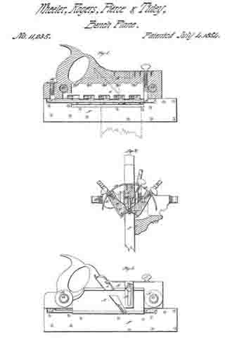
Be it known that I, JOEL BRYANT, of the city of Brooklyn, in the county of Kings and State of New York, have invented an Improvement in Bench or Carpenters’ Planes: and I hereby declare that the following is a full and correct description thereof, to wit:

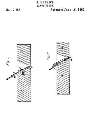
The nature of my invention consists in removing the recess, back of the plane iron — formed by the lower edge or tip of the plane stock, and the bevel edge of the plane iron — the said recess serving no purpose whatever, but, as is well known, a troublesome annoyance in catching splinters and small pieces of wood, obstructing the use of the plane. And, also, in addition to the removal of the recess, I have invented a new and more convenient method ot securing the plane iron and its cap together (where a cap is used), and, in the plane stock, by means of a single screw bolt and a sunken nut, the said screw and nut operating in connection with the plane iron and cap, as shown in the accompanying drawings Figure 1. and by the letters and figures marked thereon and forming a part of this specification.

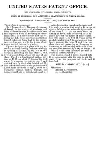
Fig. 1, in the accompanying drawings, is a longitudinal section of a bench plane, showing my improvement in the removal of the recess (R, Fig. 2,) as found in ordinary bench planes (Fig. 2). The recess (R, Fig. 2,) being removed by cutting off, or dispensing with the lower edge or tip (L, Fig. 2,) as far up in the stock (A,) as the upper part of the bevel of the plane iron goes to where the said plane iron (P) fits snugly to its bed in the plane stock (A) leaving in its room and stead an opening (O), having a backward inclination for the easy transit of any bits or small pieces that might pass the plane iron (P,) the said opening (O) being thus bounded on all sides by the snugly fitted plane iron (P) in the bed of the plane stock (A) it leaves no lissures or crevices in which splinters or bits of wood can fasten or stick; and thus, by this simple device, a most troublesome and vexatious annoyance is got rid of, without any inconvenience or disadvantage whatever, the said lower edge or tip (L) being of no use.

The other improvement in bench planes, is plainly shown in the said Fig. 1 by the screw bolt (B,) with its head (h) and shank (S,) in connection with the plane iron (P) and cap (C), and the sunken nut (N). The said shank (S,) being provided with a screw thread, passes through the said plane iron (P,) and cap (C) enters and fastens into the said sunken nut (N,) having a corresponding screw thread cut therein, the said screw bolt (B,) is screwed down into the said sunken nut (N,) and left with its head (h) resting upon, binding together, and firmly securing the said plane iron (P,) and cap (C,) in their place and bed in the plane stock (A), thus avoiding by this improvement the use of a wedge, or any other complicated contrivance for securing the plane iron and cap together and in the plane stock, thereby saving expense in the construction of plane stocks, and gaining an advantage and convenience in adjusting and securing plane irons over any other contrivance hitherto known or used.

I am aware that metal plane stocks have been invented with an iron tip for filling the said recess which I remove. I am also aware that an invention exists for securing the plane iron and its cap together and afterward, in the plane stock, by means of a “hook headed bolt, two nuts, and a cam shaft,” but these are essentially different from my invention; therefore, disclaiming all and every other alleged iinprovement in bench planes, (unless substantially the same as is herein set forth and described as my invention,) I institute my claim for what I desire to secure by Letters Patent as follows, to wit:

I claim the construction and use ot bench planes having an opening with a backward inclination made by the dispensing with, or the removal of the lower edge or tip of the plane stock ( as existing in bench planes of ordinary construction), the said opening being made for the purpose of avoiding the annoyance produced by splinters or small pieces of wood fastening into the recess, as formed by the said lower edge or lip of the plane stock and the bevel of the plane iron (in common bench planes) substantially as herein described and for the purpose set forth.

JOEL BRYANT.

Witnesses:
A. H. BIGELOW,
MELVILLE BRYANT.

No. 17,618 – Holding And Adjusting Plane Irons In Their Stocks (Willard W. Chipman) (1857)

[paiddownloads id=”45″]17618


UNITED STATES PATENT OFFICE.

_________________

WILLARD W. CHIPMAN, OF LOWELL, MASSACHUSETTS.

METHOD OF HOLDING AND ADJUSTING PLANE-IRONS IN THEIR STOCKS.

_________________

Specification of Letters Patent No. 17,618, dated June 23, 1857.

_________________

To all whom it may concern:

Be it known that I, WILLARD W. CHIPMAN, of Lowell, in the county of Middlesex and Commonwealth of Massachusetts, have invented certain new and useful Improvements in Apparatus for Holding and Adjusting Plane-Irons; and I do hereby declare the following to be a full, clear, and exact description thereof, reference being had to the accompanying drawings and to the letters of reference marked thereon.

Similar letters of reference in each of the several figures refer to like parts.

Figure 1 is a side elevation of a plane with my improvements attached. Fig. 2 is a longitudinal vertical section of the same. Fig. 3 is a cross section perpendicular to the direction of the plane iron. Fig. 4. is a plan of a part of the apparatus, shown detached from the plane stock. Fig. 5 is an end view of the same.

A represents the stock, or main part of the plane. B is the handle, C is the iron, or cutting tool, D is the cap which is secured on the face of C in the usual manner by means of the screw F. This cap may, or may not be used.

Fastened to the back of the “iron” C is a double V or sliding piece E which has a slot running longitudinally through the middle of it large enough to admit the head of the screw F.

G, G is a small metallic frame having a V shaped groove on each side in which the sliding piece E is supported. A suitable place is cut out in the plane stock directly beneath the iron C to receive this frame G and it is secured therein by means of screws.

H, H’ are frogs or wedge shaped pieces secured in the grooves of the frame G, G by means of a joint so that one end is at liberty to swing in or out. These frogs are operated upon by means of the thumb screws I, I’, which screw through the sides of frame G and press against the movable end of the frogs. The heads of the thumb screws I, I’ are sunk in recesses made, one on each side of the plane stock and just large enough to allow the thumb and finger to have a fair chance to turn the screws. Now when the frogs are thrown back in the grooves, the slide E is at liberty to move up or down in them (the grooves) freely, and the “plane iron” can be adjusted to its proper place, which being done, the thumb screws are turned up against the frogs, and these bind or wedge the sliding piece E into the grooves, and thus the plane iron is secured firmly in its place. One advantage in this manner of securing the plane iron is, that it leaves the mouth of the plane through which the shavings come perfectly smooth and free from all the obstructions that are found in the common plane, so that the shavings cannot clog in the mouth and cause trouble to the operator. Another advantage is in the facility it affords of adjusting the iron to the right gage, and also of setting it. square. If, as it often happens, one side of the edge of the iron projects through the mouth more than the other, then we must loosen the screw on the side where the edge shows least and screw up the other, until the edge comes into the right position. This simple and positive operation is an evident advantage over the old uncertain way of rapping the top of the iron with a hammer.

Having thus described my invention, what I claim as new and desire to secure by Letters Patent, is —

The use and application of the apparatus for holding and adjusting the plane iron, substantially as, and for the purpose described.

In witness whereof I have hereunto set my signature this twenty fifth day of May A. D. 1857.

WILLARD W. CHIPMAN.

In presence of us —
N. WRIGHT,
O. E. CUSHING.

No. 17,645 – Securing And Adjusting Plane Irons In Their Stocks (William Stoddard) (1857)

[paiddownloads id=”46″]17645


UNITED STATES PATENT OFFICE.

_________________

WM. STODDARD, OF LOWELL, MASSACHUSETTS.

MODE OF SECURING AND ADJUSTING PLANE-IRONS IN THEIR STOCKS.

_________________

Specification of Letters Patent No. 17,645, dated June 23, 1857.

_________________

To all whom it may concern:

Be it known that I, WM. STODDARD, of Lowell, in the county of Middlesex and State of Massachusetts, have invented a new and Improved Mode of Fastening in Plane-Irons; and I do hereby declare that the following is a full, clear, and exact description thereof, reference being had to the accompanying drawings, and to the letters of reference marked thereon, in which —

Figure 1 is a plan of a plane with my invention attached showing the lever A through an opening in the iron B ; Fig. 2 is an end elevation presenting the cam stand C and lever A as seen from a back end view of the plane ; Fig. 3 is a longitudinal vertical section on D, E, on which F denotes the tool stock; G, a cap on the cutting iron B and confined to it by the double headed bolt H. This bolt slides loosely in the grooved stand I, seen more distinctly in Fig. 7, which is a transverse vertical section through the double irons B and G, bolt H, and stand I.

A is a lever acting in and on the cam stand C in such a manner that moving it to the right or left lowers or raises the upper ends of the irons B, G. At the same time the cutting or lower ends are moved in an opposite direction by means of their connection with stand I by bolt H which serves as a fulcrum for lever A to operate upon thus firnily pressing the irons B and G to the plane stock and preventing any looseness or chattering at their cutting ends as is often the case when fastened by a key or wedge.

What I claim as my invention and wish to secure by Letters Patent is —

The grooved stand I double-headed bolt H in combination with the cam A and its stand C for the purposes set forth and described.

WILLIAM STODDARD. [L. S.]

Witnesses:
ALBERT I. PHILBRICK,
H. G. BLAISDELL.

No. 17,735 – Securing The Stock To The Guide Rods Of Joiner’s Plows (Stephen Going) (1857)

[paiddownloads id=”48″]17735


UNITED STATES PATENT OFFICE.

_________________

STEPHEN GOING, OF NEW YORK, N. Y.

DEVICE FOR SECURING THE STOCK TO THE GUIDE-RODS OF JOINERS’ PLOWS.

_________________

Specification of Letters Patent No. 17,735, dated July 7, 1857.

_________________

To all whom it may concern:

Be it known that I, STEPHEN GOING, of the city, county, and State of New York, have invented a new and Improved Plow for Joiners’ Use; and I do hereby declare that the following is a full, clear, and exact description of the same, reference being had to the accompanying drawings, making a part of this specification, in which —

Figure 1 is a front view of my improvement. Fig. 2 is a longitudinal vertical section ofthe same (x) (x) Fig. 1, indicating the plane of section. Fig. 3 is also a longitudinal vertical section of the same, (y) (y) Fig. 1, indicating the plane of section.

Similar letters of reference indicate corresponding parts in the several figures.

My invention consists in the peculiar mode of securing the stock on guide-rods which are attached to the gage.

The invention has for its object the ready adjustment of the stock on the guide rods.

To enable those skilled in the art to fully understand and construct my invention, I will proceed to describe it.

A represents the gage to which two parallel cylindrical rods B, B, are attached. The gage is of the usual construction, and the rods B, B, which are guide rods, are attached to the gage in the usual way.

The guide rods B, B, ass transversely through the stock C. This stock is constructed in the usual manner.

Within the stock C a metallic rod or bar D is placed. The bar D is fitted in a recess (a) in the stock, and the lower end of a screw E is fitted into the center of the bar D. The screw E passes vertically into the stock C, and the ends of the bar D have each a concave surface as shown at (b) Fig. 3, and these concave surfaces (b) are at the bottom of the circular openings through which the guide rods B, B, pass. The recess (a) in the stock is made sufficiently large to allow a certain degree of vertical play or movement to the bar D, so that when the bar D is forced down to the lower part of the recess (a) by turning the screw E, the stock will be allowed to work freely back and forth on the guide rods. And when the stock is to be secured on the rods the concave surfaces (b) are pressed or bound firmly up a ainst the rods B, so that the stock will be firmly clamped to them. By this means the stock C may be readily moved and secured at any desired point on the rods B, and the parallelism of the stock and gage will always be preserved.

F represents the iron which is fitted in an inclined mortise in the stock. This mortise is of slightly taper form longitudinally, and a wooden key G is litted therein.

H is a screw-rod, which asses obliquely into the stock C, and at right angles to the face of the iron F. The inner part of the screw rod passes through a nut (c) placed in the stock as shown in Fig. 2, and the inner end of the rod, which has a journal (d)
formed on it, is fitted in a recess in the key G.

It will be seen from the above description of parts that by merely turning the screw-rod H, the key G may be made to press tightly against the iron F and secure the same firmly in the mortise. And as the screw-rod H , passes into the key G at right angles to it tlhe back of the iron F will be pressed firmly against the back of the mortise, and the iron will thus be prevented from working loose in the mortise. The great advantage in this arrangement is the relative position of the screw-rod with the iron and key, namely, at right angles. If the screw-rod were laced obliquely with the iron F, the iron wouild be liable to work loose in the mortise.

The ordinary plows, at least those of the most approved kind, have their stocks rendered adjustable on their guide rods by having screw-threads formed on said rods, and nuts and followers fitted thereon. The objection to the most modern plow now in use is that considerable time is lost in adjusting the iron placed in said stock at any parallel line required. By my improvement the iron in said stock may be adjusted with the greatest facility and also at parallel lines at any point of said guide rods.

Having thus described my invention, what I claim as new and desire to secure by Letters Patent is:

Securing the stock C, on the guide-rods B, B, by means of the bar D, fitted within the stock and actuated by the screw E, substantially as and for the purpose set forth.

STEPHEN GOING.

Witnesses:
W. TUSCH,
J. F. BUCKLEY.

No. 723,143 – Wood Scraper (Louis F. Deffaulx) (1903)

[paiddownloads id=”66″]723143


UNITED STATES PATENT OFFICE.

_________________

LOUIS F. DEFFAULX, OF INDIANAPOLIS, INDIANA.

WOOD-SCRAPER.

_________________

SPECIFICATION forming part of Letters Patent No. 723,143, dated March 17, 1903.
Application filed July 30, 1902. Serial No. 117,615. (No model.)

_________________

To all whom it may concern:

Be it known that I, LOUIS F. DEFFAULX, a citizen of the United States, residing at Indianapolis, in the county of Marion and State of Indiana, have invented new and useful Improvements in Wood-Scrapers: and I do declare the following to be a full, clear, and exact description of the invention, reference being had to the accompanying drawings, and to the letters of reference marked thereon, which form a part of this specification.

My invention relates to tools for scraping the surfaces of wooden floors, siding, furniture and the like ; and has reference more particularly to scrapers that are designed to be held when in use in the hands of the operator.

The object of the invention is to provide an improved scraper of the character above referred to that may be cheaply constructed, capable of doing superior work, and be durable and economical in use.

The invention consists in the application to a scraper and the stock thereof of an elastic bearing for the scraper ; and it consists also in the novel parts and in the combination of parts, as hereinafter particularly described, and pointed out in the claims.

Referring to the drawings, in which similar reference characters indicate corresponding parts, Figure 1 represents a front elevation view of a hand-scraper constructed in accordance with my invention ; Fig. 2, a view of the bottom thereof ; Fig. 3, a fragmentary view of the bottom, enlarged so as to more clearly show the scraper-bearing ; Fig. 4, a central vertical sectional view transversely of the plane of the scraper, and Fig. 5 a perspective view of the elastic scraper-bearing.

In constructing the scraper I provide a suitable stock A, the bottom of which is a plane and the front of which is slightly oblique to the bottom. The stock for the hand-scrapers is provided with a pair of curved handles a a at the sides thereof. The elastic scraper-bearing B, preferably formed of rubber, has thin ends b b and a relatively thick central portion d, the rear face of the bearing being flat and the front face thereof arched. The bearing is set with its rear face against the front face of the stock A, the latter being preferably slightly recessed to receive a portion of the bearing. A gage C, having feet D D, is secured to the front face of the stock by means of screws e e and extends horizontally across the lower portion of the face, the lower part of the gage having a plane face situated in the same plane as that of the lower face of the stock. The heels E E of the feet are suitably curved and extend over the ends of the bearing B.

The scraper F is formed as a thin plate of steel and has a suitably dressed and sharpened scraping edge f. It is placed with its rear side against the curved front face of the bearing B, and the heels E E are placed against the front side of the craper. By means of the screws e e the scraper plate or blade is forced against its bearing B and sprung so as to assume the same curvature as that of the face of the bearing. The screws secure the scraper in the position in which it may be adjusted. It will thus be seen that the scraper-blade is seated against a slightly-elastic bearing, whereby improved results are attained, the blade having a more intimate contact with its seat than would be possible if the seat were hard or rigid and not self-fitting, as the bearing B is.

In practical use the tool is to be pushed upon the wood with the blade at the front of the stock, in the usual manner.

Having thus described my invention, what I claim as new is —

1. A wood-scraper provided with an elastic blade seat or bearing having a crowning or arched face, and a scraping-blade secured against the crowning or arched face of the elastic seat.
2. A wood-scraper provided with an insertible blade seat or bearing having a crowning or arched face, and a scraping-blade having a curved scraping edge and secured against the crowning or arched face of the insertible seat.
3. A wood-scraper comprising a stock, an elastic bearing having a curved front face and seated against the stock, a scraping-blade seated against the front face of the bearing, and a clamping-gage secured to the stock and engaging the blade.
4. A wood-scraper provided with an insertible elastic blade seat or baring having thin ends and a relitively thick central portion, and a scraping-blade secured against the elastic seat.

In testimony whereof I affix my signature in presence of two witnesses.

LOUIS F. DEFFAULX.

Witnesses:
WM. H. PAYNE,
E. T. SILVIUS.

No. 98,305 – Whalebone Shaving Plane (James A. Sevey) (1869)

[paiddownloads id=”53″]98305


UNITED STATES PATENT OFFICE.


JAMES A. SEVEY, OF BOSTON, MASSACHUSETTS.

Letters Patent No. 98,305, dated December 28, 1869.
_________________

IMPROVEMENT IN PLANE FOR SHAVING WHALEBONE.

_________________

The Schedule referred to in these Letters Patent and making part of the same.

_________________

To all persons to whom these presents may come:

Be it known that I, JAMES A. SEVEY, of Boston, in the county of Suffolk, and State of Massachusetts, have invented a new and useful or Improved Machine or Implement for Stripping or Shaving Whalebone ; and I do hereby declare the same to be fully described in the following specification, and represented in the accompanying drawings, of which —

Figure 1 denotes a perspective view of it :
Figure 2, a verticle and longitudinal section ; and
Figure 3, a transverse section of it.

In such drawings —

E denotes a plane-stock, made of wood, or other proper material, and provided with a handle, a, which extends from it in manner as exibited in figs. 1 and 2.

At or near its heel, the said stock is rebated entirely across it, as shown at b c d, in fig. 2, and also in fig. 1.

Within the recess or rebate, I arrange, at suitable distances apart, and parallel to each other, two metallic blocks or plane-iron supporters A A, they being rebated on their inner edges, as shown at e e, in fig. 3, in order to receive and support a plane-iron or cutter, C, the bevel f of whose cutting-edge, is arranged upward, or in a manner as shown in fig. 2.

The plane-iron C is held to these supporters A A by means of clamp-screws g g, screwed into the supporters, and arranged, with reference to the plane-iron, in manner as represented.

Each supporter is held in place by three screws, S S P, two of which go through the supporter and screw into the plane-stock. The third screw, P, is arranged between the screws S S, and is screwed through the plane-stock, and against the supporter, the whole being as shown in fig. 2.

By means of these adjusting-screws S S P, the inclination or bevel of the knife or plane-iron can be so adjusted as to bring the cutting-edge thereof down to a plane, L L, which extends from the lower edge of the front end of a plate-spring, M, to the lower edges of the four screws g g.

In advance of the plane-iron C there is a spring-plate or throat-piece M, which is secured to the plane-stock E by means of two screws, B B, which go through slots h h, (made in the plate M,) and screw into the stock.

Furthermore, certain adjusting-screws, D D D, screw down through the stock E, and against the upper surface of the plate M. These screws, with the screws BB, and the slots h h, are to adjust the elastic throat-piece M, or enable it to be perfectly adjusted with reference to the cutting-edge of the plane-iron C.

The implement is to be used in the manner of a common carpenter’s plane, the spring-plate M being first properly adjusted, with reference to the cutting-edge of the plane-iron, so as to cause such edge, when forced against the end of a slab of whalebone, to strike it at the requisite depth.

As soon as the plane-iron enters the slab, the incline f will raise the shaving or part to be split, or force it up from the part below it, so as to split it therefrom.

The spring-plate or throat-piece, operating in conjunction with the knife-edge of the plane f, will not only yield, so as to allow the plane-iron to hit the end of the lab at the proper depth, but will afterward press upon the upper surface of the portion to be removed, and hold the whole down to the bench.

The implement, on being moved forward, will separate a strip of even thickness from the slab, however irregular the slab may be on its upper surface.

I am aware of the plane described in the United States patent, No. 50,947, dated November 14, 1865, and granted to Harrison Ogborn, and I make no claim thereto. My plane differs from it, in having its cutter C sustained by two adjustable supporters A A, which answer not only as means of holding the cutter, but as guides for the shaving, to direct it properly through and out the plane.

My plane also has the elastic throat-piece M. provided with adjustments, by which it can be adjusted both laterally and longitudinally, with respect to the edge of the plane-iron C ; whereas, the throat-piece of Ogborn’s plane is inelastic, and adjustable only laterally, or up and down.

The elastic or spring throat-piece M does not project over the plane-iron, but is arranged in front of it, and with its working end in the same plane with the cutting-edge of the knife C.

In order for the knife C to cut, the throat-piece M must first spring upward, and, while the shaving is being cut, the throat-piece is borne down on it by the inherent elastic force of the throat-piece, the same enabling very thin, and smooth, and even shavings to be removed from the whalebone. Consequently,

What I claim as my invention is as follows :

The combination and arrangement of the spring or elastic throat-piece M, (provided with adjusting-devices, as described,) with the plane-stock E, and the cutter or plane-iron C.

Also, the combination and arrangement of the plane-iron supporters A A, and the clamp-screws g, and adjusting-screws S S P, with the plane-stock E, the cutter C, and the mouth-piece M, provided with devices for adjusting it, as set forth.

J. A. SEVEY.

Witnesses:
R. H. EDDY,
F. P. HALE, Jr.

No. 89,369 – Low Angle Bench Plane (Stephen W. Woodward) (1869)

[paiddownloads id=”52″]89369


UNITED STATES PATENT OFFICE.


STEPHEN W. WOODWARD, OF BUFFALO, NEW YORK.

Letters Patent No. 89,369, dated April 27, 1869; antedated April 16, 1869.
_________________

IMPROVEMENTS IN PLANE FOR CARPENTERS’ USE.

_________________

The Schedule referred to in these Letters Patent and making part of the same.

_________________

To all whom it may concern:

Be it known that I, STEPHEN W. WOODWARD, of the city of Buffalo, in the county of Erie, and State of New York, have invented certain new and useful Improvements in Planes for Carpenters’, Joiners’, or Cabinet-Makers’ Use ; and do hereby declare the following to be full, clear, and exact description there-of, reference being had to the accompanying drawings, and to the letters of reference marked thereon.

The nature of my invention consists in the manner of placing the plane-iron with its face downward, holding the cutting-edge of the same firmly in any required position, and elevating or lowering, forcing outward or withdrawing the same, by means of screws and pins.

In order to enable others skilled in the art to make and use my invention, I will now proceed to describe its construction and operation, referring to the annexed drawings, which form a part of this specification, and in which —

Figure 1 is a dissected view of the plane, and
Figure 2 is a sectional view of the same.

Fig. 1 represents a cast-iron plane, with a slot marked a cast in the body of the plane, for the purpose of guiding and holding a screw marked b, the operation of which screw is intended to elevate or depress the cutting-edge of the plane-iron, at the same time opening and closing the throat of the plane, so as to gauge the thickness of the shaving or cut.

C represents a thumb-screw attached to the plane-iron, for the purpose of forcing outward, withdrawing, and at the same time assisting to hold in any required position, the cutting-edge of the plane-iron.

This screw C enters the sleeve I, which is hinged or pivoted in such a manner to the rear end of the plane-bit E, that said end may be adjusted vertically without affecting the screw.

The screw C not being cramped by the movement of the rear end of the plane-bit, is left free to act upon said bit, for giving it an endwise adjustment at any angle it may assume.

d represents the cap, with screw d, holding the plane-iron firmly in its place.

This cap is caught beneath two pins, or lugs J, on the inner faces of the flanges, forming the sides of the plane, and with its screw d, serves to press down and hold in position the forward end of the same bit.

Having thus fully described my invention,
What I claim as new, and desire to secure by Letters Patent, is —

The sleeve I, provided with jaws, and pivoted to the bit E, arranged with the screws C and b, to operate as set forth.

STEPHEN W. WOODWARD.

Witnesses:
J. H. BARTON,
W. C. SHERWOOD.

No. 81,795 – Bench Plane For Cutting Blind-Slats (Carl Kupfer) (1868)

[paiddownloads id=”51″]81795


United States Patent Office.


CARL KUPFER, OF MADISON, WISCONSIN, ASSIGNOR TO HIMSELF AND KUND
J. FLEISCHER, OF SAME PLACE.

Letters Patent No. 81,795, dated September 1, 1868.

IMPROVEMENT IN PLANES FOR CUTTING BLIND-SLATS.

_________________

Specification of Letters Patent No. 81,795 dated July 4, 1854.

_________________

The Schedule referred to in these Letters Patent and making part of the same.

_________________

TO ALL WHOM IT MAY CONCERN:

Be it known that I, CARL KUPFER, of Madison in the county of Dane, and State of Wisconsin, have made new and useful Improvements in Slat-Cutting Machinery ; and I do hereby declare the following to be a full, clear, and exact description of the nature, construction, and operation of the same, sufficient to enable one skilled in the art to which it appertains to construct and use the same, reference being had to the accompanying drawings, which are made part of this specification, and in which —

Figure 1 is a perspective view.
Figure 2 is an end sectional view.
Figure 3 is an enlarged side sectional view.
Figure 4 is a side sectional view.

The invention consists in the construction of a knife or plane bit, whose edge or edges are so shaped, arranged, and combined as to cut the top, sides and bottom of the slat at one stroke of the plane across the stick of timber from which the slat is to be cut, and in leaving a straight edge or side, against which the shoulder of the plane is brought, and which serves as a guide for the plane in cutting each succeeding slat.

The bit A is made of a piece of steel, of suitable dimensions for the size of the slat to be cut, with its lower cutting-end, B, bent to an angle of forty-five degrees, or thereabouts, from the line of the body of the bit, and projecting downwards, as shown at B, fig 4. This projection is pierced with a hole, as at C, fig. 2, of any desired shape for the slat, and in line with the face of the plane D, as shown at C, fig. 2; the upper and lower edges of the aperture being brought to sharp cutting-edges, as at 1 2, fig. 2.

In sharpening these edges, care must be taken to leave two lips, whose edges, 3 4, fig. 2, are at right angles with the upper and lower cutting-edges 1 2. The bit A is set in a plane-stock, D, and secured in the ordinary manner with a wedge, E, there being sufficient throat, F, for the escape of all shavings. The front end of the plane-stock is provided with a handle, G, to facilitate holding the tool firmly.

By the use of this tool I am enabled to avoid the use of sawed lumber of any kind, and, instead, use timber as it is split from the log, like fire-wood, or without splitting at all, and thus I save from one-half to nine-tenths of the timber, and consequently a large proportion of the cash outlay formerly paid for stock.

Having described my invention, what I claim, and desire to secure by Letters Patent, is —

1. The bit A, when constructed with sharpened upper and lower edges, 1 and 2, leaving two lips, 3 and 4, said lips to be at right angles with the upper and lower cutting-edges, substantially as and for the purpose set forth.

2. The combination of the bit A, as described and claimed, with the plane-stock, for the use and purposes specified.

CARL KUPFER.

Witnesses:
J. C. SCHELTE,
A. JURGENS.

No. 13,957 – Patternmakers Core Box Plane (John P. Robinson) (1855)

[paiddownloads id=”27″]13957


UNITED STATES PATENT OFFICE.

_________________

JOHN P. ROBINSON, OF MATTEAWAN, NEW YORK.

PLANE FOR FINISHING GROOVES IN PATTERNS &c.

_________________

Specification of Letters Patent No. 13,957, dated December 18, 1855.

_________________

To all whom it may concern:

Be it known that I, JOHN P. ROBINSON, of Matteawan, in the county of Dutchess and State of New York, have invented a new and Improved Plane for Cutting or Forming Grooves Designed Chiefly for Patternmakers’ Use; and I do hereby declare that the following is a full, clear, and exact description of the same, reference being had to the annexed drawings, making a part of this specification, in which —

Figure 1, is an ened view of my improvement. Fig. 2, is a longitudinal verticle section of ditto, the plane of section being through the center. Figs. 3, 4, 5 are end views of my improvement in different positions showing the manner in which the grooves are formed. Fig. 6, is an end view of ditto, the form of the plane being slightly varied from those shown in the proceeding figures. Fig. 7, is a perspective view of the block of wood showing a taper groove formed by my improvement.

Similar letters of reference indicate coresponding parts in the several figures.

My invention consists in having the stock of the plane made in triangular or three sided prismatic form the cutting edge of the iron being at the junction of it’s two lower sides and shaped to correspond to the form of the sides as will be presently shown and described whereby half round and other shaped grooves of different sizes may be cut.

To enable those skilled in the art to fully understand and construct my invention, I will proceed to describe it.

A, represents the stock or body of the plane which is of triangular or three sided prismatic form.

B, represents the plane iron which passes through the center of the upper side of the plane stock, the cutting edge of the plane iron is pointed or has beveled edges corresponding with the inclination of the two lower sides of the stock as shown clearly in Fig. 1.

In Figs 1, 3, 4 and 5, the two lower sides of the stock meet at a right angle, and in Fig. 6 the angle formed by the junction of the two lower sides is acute or less than a right angle.

The width of the plane iron, B, is such that each of the lower sides of the stock will have a suitable length of cutting edge of the iron projecting through it, a suitable thwart C, being made through the stock as shown in Fig. 2.

The plane is used in the following manner: The stuff in which the groove is to be cut is marked or lined to indicate the desired width of the groove. The spaces between the marks or lines may then be chipped or roughed out a requisite depth as desired with a gouge or other instrument, or the whole of the groove may be cut with the plane, if the latter plan is preferred a shallow cut is made by the plane on each line or mark, and the edge of the plane formed by the junction of the two lower sides is placed in one of these cuts as shown in Fig. 3 and the plane operated similar to other tools of the kind. One side or edge only of the plane iron cuts in the groove and when the plane has cut one half of the groove it, the plane, will be in an upright position as shown in Fig. 4. The lower edge of the stock is then placed in the opposite cut and the other half of the groove is cut. The plane stock being of triangular form rests against the edges of the groove and determines its depth, so that if the two lower sides of the stock are at right angles to each other, the groove will be of semi-circular form, as shown in Figs. 1, 3, 4 and 5 but if the lower sides form an acute angle as shown in Fig. 6 the groove will be a semi-ellipse deeper than it is wide and if the sides form an obtuse angle the groove will be wider than it is deep.

Grooves may be made of taper form as shown at D, fig 7, and they may be made of any width and depth, the depth of course corresponding to the width and angle formed by the two lower sides of the stock.

The above implement or tool is intended chiefly for patternmakers’ use, where grooves of varying sizes require to be made.

Having thus described my invention, what I claim as new and desire to secure by Letters Patent is,

Constructing the plane stock A, of triangular or three sided prismatic form, the two lower sides forming a greater or less angle with each other and the plane iron, B, fitted in the stock as shown for the purpose set forth.

JOHN. P. ROBINSON.

Witnesses:
CHAUNCEY GREEN,
ADOLPHUS VANDEWATER.

No. 11,235 – Beveling Plane (Wheeler, Rogers, Pierce & Tidey) (1854)

[paiddownloads id=”13″]11235


UNITED STATES PATENT OFFICE.

_________________

M. J. WHEELER, G. W. ROGERS, H. W. PIERCE AND M. B. TIDEY, OF DUNDEE, NEW YORK.

BEVELING-PLANE.

_________________

Specification of Letters Patent No. 11,235, dated July 4, 1854.

_________________

To all whom it may concern:

Be it known that we, M. J. WHEELER, G. W. ROGERS, H. W. PIERCE, and M. B. TIDEY, of Dundee, in the county of Yates and State of New York, have invented certain new and useful Improvements in Beveling-Planes; and do not hereby declare that the following is a full, clear, and exact description of the same, reference being had to the accompanying drawings, forming part of the specification, in which–

Figure 1, is a longitudinal section taken directly through the center of the body of a plane, constructed according to our invention. Fig. 2, is a side view.

Similar letters of reference indicate corresponding parts in the several figures.

The object of this invention is to plane a double bevel, or in other words, to plane two faces at any desired angle to each other and to a third face.

The invention consists in attaching the two cutters which are to plane the two faces to two wings which are both hinged or otherwise attached to the body of the plane, so as to swing around a common axis, and each of which is adjustable and capable of being secured in any position, independently of the other, so as to bring and set the faces of the cutters at any angle to each other or to the fence which is employed to guide the plane.

To enable those skilled in the art to make and use our invention, we will proceed to describe its construction and operation.

A, is the body of the plane.

B, B, are the wings which contain the cutters, f, f, and are connected to the under side of the body, A, by a three flanged hinge, c, c, c’, which is best illustrated in Fig. 2. One flange, c’, of this hinge is inserted into the body, A, and secured by screws, d, d. The screws, c, c, are secured, one to each of the faces of the wings, B, B, and all are united by a pin, e, running the whole length of the wings. The wings are shorter than the body, A, and a recess, g, (see Fig. 2), equal in length to the wings, is cut in each side of the latter, to allow them to lie close up to the sides of it and bring their faces and the edges of their cutters as nearly as is desirable in the same plane. The cutters are of the usual form and secured in the wings by wedges, O, ), in the usual way. The wings swing within a bar, D, which is in the form of part of a circle described from the pin or axis, e, and are secured in any position by means of set screws, E, E, passing through slots in the bar, D, and screwing into their backs, as shown in Fig. 2. The upper surface of the bar, D, is graduated in degrees, commencing in both directions from the sides of the body, A, in order to enable the faces of the wings to be set at any desired angle.

F, is the fence having the screws, G, G, firmly attached to it, perpendicularly to its face. Said screws pass through holes in the body, and being furnished on one side thereof with a nut, H, and on the other side with a follower, I, to adjust the fence to the body and wings, for the purpose of planing stuff of various widths.

K, is the depth gage which is adjusted by means of the screws, L, and M, for the purpose of enabling the tool to cut to the required depth to perfect the bevel and no farther.

The operation of the plane can be best explained by illustrating the beveling of a door stile on opposite sides of the channel, which receives the panel. The stile, P, is represented in Fig. 2. The fence, F, is adjusted by the screws, G, G, to bring the depth gage to the proper distance from the side of the stile. The wings are adjusted to set the edges of the cutters at the proper angle to each other and to the face of the stile, and the depth gage is set to the proper depth. The edge of the stile is then planed down till the depth gage comes in contact with the bottom of the groove.

If it be desired, the two sides of the channel may have different bevels, as each wing, with its cutter, is adjustable independently of the other.

By making the edges of the cutters of this plane of proper form coves, ovolos, ogees, or moldings of any other form may be produced on the edges of the stuff.

What we claim as our invention, and desire to secure by Letters Patent, is:–

Attaching the two bevel cutters, f, f, to two wings, B, B, which are hinged by a three flanged hinge, c, c, c’, or otherwise so secured to the body, A, of the plane, as to be capable of swinging a certain distance around a common pivot or axis, e, for the purpose of being adjusted to set their faces and the edges of their cutters at any angle to each other and to the face of the fence, F.

M. J. WHEELER.
G. W. ROGERS.
H. W. PIERCE.
M. B. TIDEY.

Witnesses:
S. S. BENHAM,
H. CHURCH.