No. 98,108 – Improvement In Carpenters Plow (Royal B. Rice) (1869)

[paiddownloads id=”159″]98108


United States Patent Office.


ROYAL B. RICE, OF WILLIAMSBURG, MASSACHUSETTS.

Letters Patent No. 98,108, dated December 21, 1869.

_________________

IMPROVEMENT IN CARPENTERS’ PLOW.

_________________

The Schedule referred to in these Letters Patent and making part of the same.

_________________

To all whom it may concern:

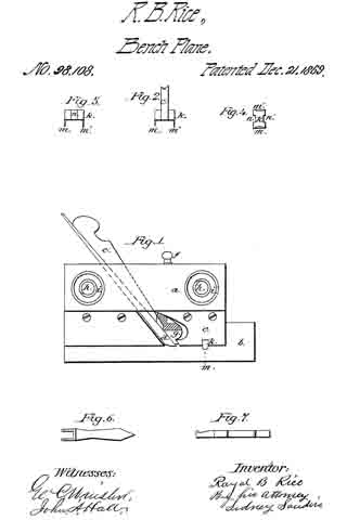
Be it known that I, ROYAL B. RICE, of Williamsburg, in the county of Hampshire, und State of Massachusetts, have made and invented n new and useful Improvement in Carpenters’ Matching-Planes; and I do hereby declare that the following is a full, clear, und exact description of the construction and operation of the same, reference being had to the annexed druwings, making a part of this specification, in which —

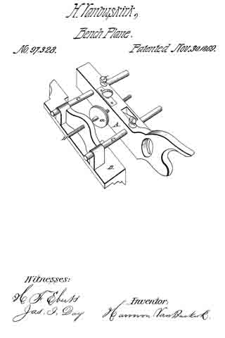
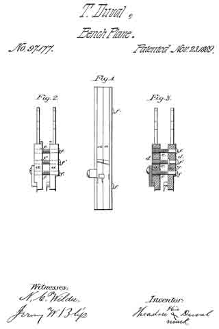
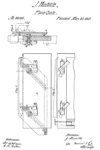
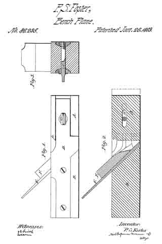
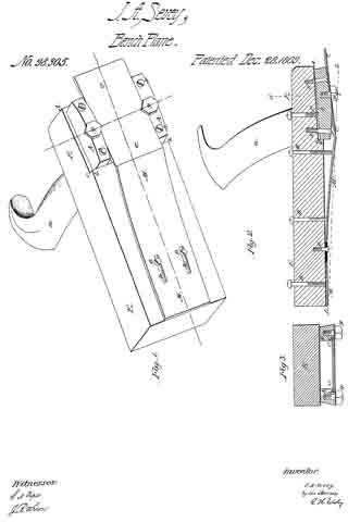
Figure 1 is a side elevation of a plane embodying my improvement.
Figure 2, a detached end elevation of the plate in which is arranged the coulter.
Figure 3, at side elevation of the coulter detached from the plate,
Figure 4, at plan of the coulter inverted.
Figures 6 and 7, side and edge elevations of at tool for removing the coulter irom the plate.
In the accompanying drawings —

The part marked a represents the wood or body.
b, the fence.
c, the plate.
d, the bit.
e, the key.
f, the screw-knob, by turning which the foot g is raised or depressed, and the depth of the furrow thereby regulated.

h h’ are screws, provided with nuts i i’, also with corresponding nuts on the opposite side of the wood a, whereby is regulated the distance of the fence b from the plate c.

My invention consists in so constructing and arranging at coulter, with reference to the bit or iron d, that in “touguing” or “grooving” lumber, the edges of the shavings to be removed by the bit d shall have been previously cut by the coulter k, greatly facilitating such operations.

In practice, I make the coulter k of a rectangular form, providing the same with depending cutting-lips m m’, end with rebates n n’‘. In the plate c, I cut a notch, wherein I arrange the coulter, as in figs. 1 and 2. The coulter k is held in piece simply by fitting the notch in plate c snugly.

The lips m m, being lower than the bit d, first out the edges of the shavings, which are then removed by said bit.

The essence of my invention is the combination of the lips m m’ with the bit d.

By means of the tool represented in figs. 6 and 7 , the coulter k may be easily removed ffom plate c, and other coulters inserted to correspond with bits (d) of different widths that may be used in the same wood a.

Thus having described the construction and operation of my invention,

What I claim as new, and desire to secure by Letters Patent, is —

The coulter k, constructed and arranged with reference to bit d, as herein specified.

ROYAL B. RICE.

Witnesses:
T. M. CARTER,
J. B. GLEASON.

No. 97,802 – Improvement In Spoke-Shave (Joseph A. Perley) (1869)

[paiddownloads id=”157″]97802


United States Patent Office.


JOSEPH A. PERLEY, OF LYNN, MASSACHUSETTS, ASSIGNOR T0 HIMSELF AND WILLIAM H. PERLEY, OF SAME PLACE.

Letters Patent No. 97,802, dated November 14, 1869.
_________________

IMPROVEMENT IN SPOKE-SHAVE.

_________________

The Schedule referred to in these Letters Patent and making part of the same.

_________________

To all persons to whom these presents may come:

Be it known that I, JOSEPH A. PERLEY, of Lynn, of the county of Essex, and State of Massachusetts, have made a new and useful invention, having reference to Spoke and Heel-Shaves; and I do hereby declare the same to be fully described in the following specification, and represented in the accompanying drawings, of which —

Figure 1 is a top view,
Figure 2 a bottom view, and
Figure 3, a transverse section of a heel-shave, as provided with my invention, which consists in the combination and arrangement of a double-edged or duplex knife, two adjustable throat-pieces, and the two handles, the whole being substantially as hereinafter explained, and also as exhibited in the said drawings.

In such drawings —

A A denotes the two handles of the implement.

The duplex knife, shown at B, has two cutting-edges, arranged as shown at b b, it being fastened, by means of screws c c, to the handles A A, so as to form with them a stock.

Each of these handles is shaped or provided with inclined beds d d at its inner part, to receive and give support to the next adjacent ends or parts of two movable bars or throat-pieces, C C, which are fastened to the handles by clamp-screws e e e e, that screw into the throat-pieces, and pass through slots f f f f, made in the handles transversely thereof.

With the double-edged knife, and the handles and two throat-pieces constructed and combined or arranged as represented, one of the knife-edges, with its throat-piece, may be adjusted to make a “fine cut,” and the other knife-edge and throat-piece may be arranged to make a coarser or coarse cut, the same admitting of the implement being used both for paring down, or rough cutting and for finishing a heel, a work usually accomplished heretofore by two separate shaves or implements.

I claim the combination of the two handles, the double-edged knife, and the two throat-pieces, substantially in manner as specified.

JOSEPH A. PERLEY.

Witnesses:
R. H. EDDY,
S. N. PIPER.

No. 97,328 – Improvement In Carpenters’ Plows (Harmon Vanbuskirk) (1869)

[paiddownloads id=”156″]97328


UNITED STATES PATENT OFFICE.

_________________

HARMON VANBUSKIRK, OF VIENNA, MICHIGAN.

IMPROVEMENT IN CARPENTERS’ PLOWS.

_________________

Specification forming part of Letters Patent No. 97,328, dated November 30, 1869; antedated November 21, 1869.

_________________

To all whom it may concern:

Be it known that I, HARMON VANBUSKIRK, of Vienna, in the county of Genesee and State of Michigan, have invented a new and useful Improvement in Plow-Planes for Carpenters’ Use; and I do declare that the following is a true and acurate description thereof, reference being had to the accompanying drawings, and to the letters of reference marked thereon, and being a part of this specification.

The nature of this invention relates to an improvement in the construction of plow-planes for the use of carpenters and joiners, by means of which the implement maybe set for use more accurately and readily than when constructed in the ordinary manner; and it consists in the employment of a right-and-left-hand screw, and a suitable guide, and arms secured to said guide and passing through the stock.

In the drawings, A represents the stock, and B the guide, which are both constructed in the usual manner.

C are the arms, rigidly secured at one end to the guide, while the opposite ends are inserted into and pass through proper holes through the stock, which holes should be of the size of the arms, allowing them to slide freely through said holes without play.

D is a right-and-left hand screw, provided with small hand-wheel a in its longitudinal center. Suitable female screws are cut through the body A and guide B, which engage with either end of this screw.

E are set-screws passing downward through the top of the body, and are intended, when the tool is set for use, to impinge on the arms and prevent the same from slipping.

The right-and-left-hand screw may be made of wood or metal, as may be most desirable.

In plow-planes of the usual construction the arms are both provided with suitable screw-threads and nuts, rendering it necessary for the operator to adjust both ends of the implement separately, requiring considerable skill and time. With my improvement the proper set is obtained by the one screw, and the operator saves time and trouble.

What I claim as my invention, and desire to secure by Letters Patent, is —

The right-and-left-hand screw D, when used in the construction of carpenters’ plow-planes, as herein described, in combination with stock A and guide B, all operating substantially as herein set forth.

HARMON VANBUSKIRK.

Witnesses:
JAS. I. DAY,
THOS. S. SPRAGUE.

No. 97,177 – Improvement In Carpenters’ Grooving-Plane (Theodore Duval) (1869)

[paiddownloads id=”155″]97177


United States Patent Office.


THEODORE DUVAL, OF HARTFORD, CONNECTICUT.

Letters Patent No. 97,177, dated November 23, 1869.
_________________

IMPROVEMENT IN CARPENTERS’ GROOVING-PLANE.

_________________

The Schedule referred to in these Letters Patent and making part of the same.

_________________

To all whom it may concern:

Be it known that I, THEODORE DUVAL, of Hartford, county of Hartford, and State of Connecticut, have invented certain new and useful improvements in “Dadoes” or Grooving-Tool, (commonly called a “dado,”) for forming grooves in wood below the surface; and to enable others skilled in the art to make and use the same, I will proceed to describe it, referring to the drawings, in which the same letters indicate like parts in each of the figures.

The nature of this invention consists in constructing a joiners’ or carpenters’ grooving-tool, commonly called a “dado,” in two parts, so that the two parts may be easily and quickly adjusted relatively to each other, that a groove or grooves may be formed therewith of various widths.

These “dadoes,” as usually made by tool-makers, are kept on sale by tool-vendors, classified as moulding-tools, are made of various widths, to out or form grooves of certain widths, each tool for each width.

The object of this invention is to produce in one tool all that is required to form grooves of several different widths, or of any particular width, according to the thickness of a shelf, or other purpose for which said grooves may be required.

In the accompanying drawings —

Figure 1 is a face view of a “dado” constructed after this improvement.
Figure it is an end view.
Figure 3 is a cross-section view, showing how the two parts are expanded or contracted to form a groove of any given or desired width.

a, the “dado”-stocks, made in two parts, each of which parts is constructed very much in the common way of making “dadoes.”

These two parts are held in uniform relative positions with each other, and expanded or contracted to the width it is desirable the tool shall out, by means of adjusting-screws f.

d are metallic plates, fitted into depressions formed in the outsides, near the ends, and fiush with the surface of the stock. These plates are firmly secured by screws to the stock.

The plates upon one side of the tool are provided with hubs e, through which the screws f are fitted to turn in and out closely and freely.

The screws f pass through the plates d and stock, and are held in a fixed position against an endwise increment by a collar, g, recessed into and flush with the inside surface of the stock, thence the screw passes into the hubs e.

The screws f pass through the plates d and stock, into the hubs e.

The cutting-iron, gauge, or stops which regulate the depth of the groove to be cut by the tool, the spurs tor cutting the width of the groove, are all constructed very much in the common way.

Now, it will be seen that with the use of this “dado” or grooving-tool, I am enabled to adjust the double or two parts so that the grooves may be made therewith of any desirable width, thus accomplishing with one tool what heretofore has required several tools, or, in other words, has heretofore required a tool for each width of groove to be formed.

I believe I have thus shown the nature, construction, and advantage of this invention, so as to enable others skilled in the art to make and use the same therefrom.

What I claim, and desire to secure by Letters Patent, is —

As an article of manufacture, a “dado” or grooving-plane for carpenters’ use, when constructed in two parts, and made adjustable in the manner substantially as shown and described, and for the purpose specified.

THEODORE DUVAL [L. S.] his X mark

Witnesses:
N.C. WILDER,
JEREMY W. BLISS.

No. 96,258 – Improvement In Carpenters’ Planes (Georg Müller) (1869)

[paiddownloads id=”154″]96258


UNITED STATES PATENT OFFICE.

_________________

GEORG MÜLLER, OF NEW YORK, N. Y., ASSIGNOR TO HIMSELF AND FRANCIS BURNET, OF SAME PLACE.

IMPROVEMENT IN CARPENTERS’ PLANES.

_________________

Specification forming part of Letters Patent No. 96,258, dated October 26, 1869.

_________________

To all whom it may concern:

Be it known that I, GEORG MÜLLER, of the city, county, and State of New York, have invented a new and useful Improvement in Carpenters’ Planes; and I do hereby declare that the following is a full and exact description of the construction and operation of the same, reference being had to the accompanying drawings, making part of this specification, in which —

Figure 1 is a top view ofi a carpenter’s plane containing my invention; Fig. 2, a side elevation, and Fig. 3 a vertical section, of same. Fig. 4 is an under side view of the retaining-box in connection with the sliding cap-iron; Fig. 5, an inner view of retaining-box with cap-iron removed; Fig. 6, a plan of the sliding cap-iron, and Fig. 7 a longitudinal section of said iron.

This invention relates to a novel device for adjusting the cap and bit-irons of a carpenter’s plane in relation to each other and to the plane, and holding the same firmly in position by means of a swinging box or frame, which is pivoted to the plane-stock, and on which the cap-iron slides, the said box having set-screws for adjusting, retaining, and bracing the box, cap-iron, bit-iron, and plane-stock together, and at the same time rendering the cutting-irons capable ofthe nicest adjustment and stability in relation to each other and to the face of the plane-stock.

Having described the nature of my invention, I will now describe its construction and mode of operation.

In the drawings, A is the plane-stock, B the handle, and C the plane-iron or cutting-bit. D is the cap-iron, having projections e e, which slide on the ways of the box, and having, also, a lip or projection, f, at right angles to its face, in which set-screws (which pass through the end of the box marked g g g’) operate, for purposes hereinafter explained. H is the retaining-box, which receives the cap-iron D, and has ways i i, on which the projections e e of the cap-iron slide, while the projection or lip f of said cap-iron slides on the interior of the box, Fig. 4. This box H is pivoted to the plane-stock at k, and has a clamping-screw, m, for the purpose of bracing the cap and bit irons together, and against the rear, a, of the throat of the plane-stock.

To arrange my plane for operation, I place the bit C in the throat a of the plane-stock. I next set the cap-iron D within the box H and insert the adjusting and clamp screws in their places, and I place the box so equipped in the throat of the plane. I now pass the pivot k through the throat of the plane, and through the box H; and for adjustment of the cap-iron in relation to the bit-iron in a longitudinal or transverse direction I simply turn the screws g g, or either of them, (as the case may be,) back or forth, and when so adjusted hold the cap-iron D in position by the screw g’, abutting against the lip f of the cap-iron, and I next clamp the whole together by means of the screw m, when my improved plane is ready for operation.

It will be seen from the above that by means of the pivot k and clamping-screw m the box H, cap-iron D, and bit-iron C are braced firmly together and against the plane-stock, equally distributing the pressure over the surface of the part a of the throat of the plane: Furthermore, by this arrangement the box H closely tits the throat of the plane laterally, the movements of the cap-iron being pertormed within the box; besides, the box can be brought near the mouth of the plane, thereby giving strength and stability to the cutting-irons, and at the same time easy exit to the shavings, for the reason that I dispense with the prize fork or carrier F, used in the subject of a patent granted me on the 29th day of May, A. D. 1866, and on which I consider my present invention an improvement, inasmuch as the swell on the box E, for reception of the prize-fork, prevented the approach of the box toward the mouth of the plane or end of the cutting-irons, rendering the said irons partially unstable, while it also prevented the easy exit of the shavings, or rather tended to choke the throat of the plane; and, besides this, the said box E was slotted for reception of the joint-pin G, and did not fill the throat of the plane laterally, as provision had to be made for the lateral movements of the cap-iron, and both the box and prize-fork were slid together, while in my present improvement the box H is stationary, while the cap-iron D slides transversely and longitudinally on the ways of the box; and thus I produce an improvement on my former plane, which can be manufactured for two-thirds of its cost.

What I claim as my invention, and desire to secure by Letters Patents, is —

The arrangement of the stationary box H, pivoted to the plane-stock, and fitting closely the the throat thereof laterally, in combination with the cap-iron D, which is moved and adjusted beneath the said box, substantially as and for the purpose herein specified.

In testimony whereof I have hereunto set my signature this 21st day of August, A. D 1867.

GEORG MÜLLER

Witnesses:
FRANZ BERNET;
A. NEILL.

No. 96,052 – Improvement In Plane (E.G. Storke) (1869)

[paiddownloads id=”153″]96052


United States Patent Office.


E. G. STORKE, OF AUBURN, NEW YORK.

Letters Patent No. 96,052, dated October 19, 1869.
_________________

IMPROVEMENT IN PLANE.

_________________

The Schedule referred to in these Letters Patent and making part of the same.

_________________

To all whom it may concern:

Be it known that I, E. G. STORKE, of Auburn, in the county of Cayuga, and State of New York, have invented a new and useful Method of Preventing the Adhesion to the Wood, of the Faces of Metallic Planes; and I do hereby declare that the following is a full, clear, and exact description of the same, reference being had to the annexed drawing, marked “A,” making part of this specification, in which is represented the face of a metallic plane, fluted, grooved, or channelled, according to the plan of my invention.

Those flutes, grooves, or channels, may be more or less in number, and cut to a greater or less depth, provided the object be thereby attained of relieving all extra and unnecessary friction.

The object, however, is fully attained by making them about one thirty-second of an inch deep, one sixteenth of an inch broad, and one eighth of an inch asunder.

Fully one-half of the bearing-surface of the face of the plane may be thus removed, and thus to that extent diminish the points of contact, and the consequent friction, and, at the same time, preserve the full perfection of the working-face of the plane, including its throat.

It has long been known to mechanics that metallic planes have adhered to the wood much closer than wooden planes, and therefore required much more power to operate them.

This excessive friction was caused by their exact and even faces, which were not materially varied by use or atmospheric changes.

When used on very level surfaces, there were so many points of contact that the friction was troublesome, and the adhesion was further increased by atmospheric pressure, as partial vacuums would thus be formed.

The practical effect of this has been to prevent, in a large degree, the introduction and general use of metallic planes.

The object of my invention is twofold, namely, to remove about one-half of the surface of the face of the plane, so that there shall be fewer points of contact, and to form free air-channels, so that no vacuums can be formed, or any trouble arise from atmospheric pressure, however perfect the plane or true the surface on which it is moved.

I effect these two objects by fluting, grooving, or channelling the faces of metallic bench or other planes for wood-workers, as above specified, parallel to their length, or in some equivalent way.

What I claim as my invention, and desire to secure by Letters Patent, is —

A metallic plane, having the face grooved in lines parallel to the sides, in the manner and for the purpose specified.

E. G. STORKE.

Witnesses:
U. L. STORKE,
T. B. BARBER.

No. 91,990 – Improvement In Wood-Plane (Paul Viccellio) (1869)

[paiddownloads id=”152″]91990


United States Patent Office.


PAUL VICCELLIO, OF NEW ORLEANS, LOUISIANA.

Letters Patent No. 91,990, dated June 29, 1869.
_________________

IMPROVEMENT IN WOOD-PLANE.

_________________

The Schedule referred to in these Letters Patent and making part of the same.

_________________

To all whom it may concern:

Be it known that I, PAUL VICCELLIO, of the city of New Orleans, in the State of Louisiana, have invented new and valuable Improvements in Wood-Planes; and I do hereby declare that the following is a full and exact description thereof; reference being had to the accompanying drawings, and to the letters of reference marked thereon.

The object of this invention is to so construct aplane that the cap may be nicely adjusted upon the plane-bit, without regard to the distance that said bit may project beyond or below the face of the plane; and lt consists of the sliding adjustable, and perpendicular cap, as applied to and adjusted upon the plane bit.

Figure 1 is a longitudinal section of the plane;
Figure 2 is a top view ofthe plane;
Figure 3 is a perspective view of the cap and its attachments for operating it; and
Figure 4 is a back view of same.

To enable others skilled in the art to make and use my invention, I will describe its construction and operation.

A represents the wood or stock of a common smooth plane.

b is the holding-wedge to plane-bit c. The plane-bit c is set at an acute angle to the face of the plane, in order to secure an easy cut by the bit.

B represents the throat of the plane, with the rear or back side perpendicular, as seen in fig. 1.

Into the wood of the plane, on its top, is a metal plate, a’, sunk flush with the wood, and held in its place by screws e’, through holes e in plate a.

The front edge of plate a’ is recessed nearly its whole length, or so as to receive cap a in grooves that are cut therein, as seen in figs. 2 and 3, and in said grooves the cap a can freely slide.

Upon the back side of cap a is a lug-nut, a”, having a female screw-thread therein.

There is a thumb-screw D, having collars d and d’, upon each side of plate a’, so that it is securely held in its position, and upon the lower end is out a screw-thread which enters into lug-nut a”, and by turning the thumb-screw, the cap a is raised or depressed, as may be desired.

Cap a is acutely bevelled on its rear lower edge, so as to present a sharp edge upon the plane-bit c, as seen in fig. 1, and it can readily be seen that by depressing the cap by means of screw D, the most delicate adjustment of the cap upon the plane-bit can be obtained. The bit c can be taken out of the stock A, by releasing wedge b, which, in order to hold the bit firmly in position tbr cap a to act upon, is put in the rear side of said bit c, and is just as effective in holding, adjusting, or releasing the bit, as if it was placed betore it.

By placing the cap a in a perpendicular, and the bit at an acute angle with the face of the plane, the shaving is easily severed from the wood, and the cap a crimps the sharing, and insures a clear smooth out upon the wood, however cross-grained or knotty the wood may be. At the same time the cap is straight on its face, causing only a single bend of the shaving to follow up the face of the cup through the throat and out ot’ the plane, without, in the least, clogging or crimping.

The parts are all simple and cheap in construction and operation, less liable to get out of order by reason of the fewer parts, and making, as a whole, a plane of less cost, more effective and satisfactory in its use, and less trouble to manage while so in use.

I am aware that there are many devices for adjusting plane-bits in the stock, as well as many for adjusting the cap upon the bit.

I am also aware of the plane described in Patent No. 50,378, where the cap is adjusted by means of a set-screw upon the plane-bit.

None of the devices therein described do I claim, as the construction of that plane is more expensive, has more parts, thus increasing the liability to get out of repair, and so constructed that the shaving has to go through a secondary bend to be successfully discharged from the plane.

My improvement can be applied to all kinds of planes, such as jack or fore-planes, and jointers, as well as smooth-planes.

Having thus described my invention,

What I claim, and desire to secure by Letters Patent, is —

The above-described plane, when composed of the combination of the bit c, wedge b, cap a, and its adjusting-devices, with the stock A, all constructed to operate in the manner and tbr the purpose substantially as described.

PAUL VICCELLIO.

Witnesses:
WM. MANTEY,
F. LURGES.

No. 86,851 – Improvement In Moulding-Plane (A.W. Maxwell) (1869)

[paiddownloads id=”149″]86851


United States Patent Office.


A. W. MAXWELL, OF MILTON, PENNSYLVANIA.

Letters Patent No. 86,851, dated February 9, 1869.
_________________

IMPROVEMENT IN MOULDING-PLANE.

_________________

The Schedule referred to in these Letters Patent and making part of the same..

_________________

To all whom it may concern:

Be it known that I, A. W. MAXWELL, of the borough of Milton, county of Northumberland, and State of Pennsylvania, have invented a new and useful tool for moulding Wood, which I call “A Reversible Hand Moulding-Plane;” and I do hereby declare that the following is a full, clear, and exact description of the construction and operation of the same, reference being had to the annexed drawings, making a part of this specification, in which —

Figure 1 is a view representing the bottom of the plane, and
Figure 2, the top.
Letter a represents the convex centrabearing.
b, the knife-end of the bit.
c, the screws by which the bit is fastened to the body of the plane.
d, the openings in the bit, through which the screws pass, by which the bit is fastened, and by which, when unfastened, the bit may slide up or down.
e, the bit.
f, the handles of the plane.
g, the throat, partially seen, of the plane, through which the shavings of the wood pass.

The bottom of the plane is convex, the degree of convexity being greater or less, in different planes, to suit the nature of the work expected to be done.

The “centre-bearing ” a, enables the workman to reverse the plane when he desires, as, for instance, to avoid planing against the grain of the wood, or to make a smooth finish at the end of the material; and consists of a convex ridge, or bearing, running transversely across the middle of the plane, dividing the bite longitudinally into two equal parts, the knives of both of which sections, the plane being reversed, make exactly the same impressions upon the wood.

The bit e is a double bit, the one half of which is the reversed duplicate of the other, and is fastened to the body of the plane by the screws c running through the openings d, so as to allow the bit e to be moved or adjusted at pleasure.

What I claim, and desire to secure by Letters Patent, is —

The moulding-tool herein shown and described, when all the parts are constructed and arranged to operate as represented, and for the purpose set forth.

A. W. MAXWELL.

Witnesses:
FRANKLIN BOUND,
M. YOENT.

No. 88,109 – Improvement In Plane-Guide (John Woodville) (1869)

[paiddownloads id=”150″]88109


United States Patent Office.


JOHN WOODVILLE, OF CINCINNATI, OHIO.

Letters Patent No. 88,109, dated March 23, 1869.
_________________

IMPROVEMENT IN PLANE-GUIDE.

_________________

The Schedule referred to in these Letters Patent and making part of the same.

_________________

To all whom it may concern:

Be it known that I, JOHN WOODVILLE, of Cincinnati, in the county of Hamilton, and State of Ohio, have invented a new and useful Improvement in Plane-Guide and Holder; and I do hereby declare that the following is a full, clear, and exact description thereof, which will enable others skilled in the art to make and use the same, reference being had to the accompanying drawings, forming part of this specification, in which —

Figure 1 represents a back-side elevation of my improved apparatus;
Figure 2 represents afront-side elevation, with a part broken away; and
Figure 3 represents a transverse section taken on the line x x of fig. 1.

Similar letters of reference indicate like parts.

The object of this invention is to provide an adjustable holder, or clamp, for holding strips, for dressing them, and which will also serve as a guide for straightening or tapering them. It is designed more particularly to be used with the improved joiners’ plane, patented to me, November 6, 1866.

It consists of a holding-strip, or board, which is designed to be secured to a bench, with one edge upward, and which is provided with an adjustable gauge upon one side, against which the strips to be planed are clamped, by buttons and wedges on the other side of the first-mentioned holding-strip.

A represents the holding-strip, which may be secured to a bench, or in a vise, in any suitable manner, with the edge B upward.

C represents a guide and clamping-strip, which is provided with the T-headed inclined grooves D, whereby it is clamped to the strip A, by the bolts E and thumb-nuts E’; the heads F of the said bolts being arranged loosely thereon, and sliding in the wide part of the grooves D.

The holes through the strips A are elongated, and provided with the hollow bolts I, having enlarged heads arranged in the recesses H. The bolts E pass through these hollow bolts, and the office of the latter is to serve as rigid supports for the former when adjusted to the light position, and screwed up tightly by the nuts I’.

K represents clamping-buttons adjustably connected to the front face of the strip A, by the long bolts L; and

M represents wedges pivoted to the face of the strip A, in a position to be conveniently adjusted under the inclined ends of the buttons, for clamping them against the stuff to be operated upon.

The operation is as follows:

When it is designed to dress a strip with parallel and square edges, the guiding-strip C, which is provided with one edge a, and one bevelled edge b, is adjusted to the strip A, with the square edge a as high above the strip A as the designed width of the strip to be dressed the edge a being in a horizontal plane parallel with the edge of the strip A when it is clamped tight thereto by the bolts E and thumb-nuts E’.

The strip to be dressed is then placed upon the upper edge of the strip A, and clamped between the guide C and the buttons K.

The plane, which, according to the improvements patented to me as above described, is provided with an adjustable guide, d, is then placed upon the strips to be dressed, and held by the said guide, so that the edge e of the stock will project over the guide C sufficiently to arrest the cutting-action of the plane when the strip has been worked down to the point coincident with the edge of the guide C.

Any number of strips may thus be dressed to the same gauge with great uniformity, while at the same time the edges will be exactly square, if the plane-guide be adjusted to that angle.

If it is desired to dress the strips with bevelled edges, the bevelled edge b, of the guide G, is placed upward, as represented in blue lines, at b’; and if it be desired to produce tapered strips, the guide C may be adjusted to produce any taper, by loosening the bolts E and I, so as to allow the plates I to move in the recesses H, to correspond with the varying distances caused between the points of contact with the grooves D, of the heads of the bolts E, by changing the horizontal plane of the guide C.

In dressing thin strips, two or any other number, not wider in the aggregate than the plane-bit, may be clamped together, and dressed at once.

In dressing strips in this manner, in my improved guide and holder, with my improved planes, I have found it very desirable to provide the jack, or roughing-plane with an adjustable gauging-strip, f, as shown in red in fig. 3, for the purpose of arresting the cutting-action of the plane-bit, the amount of a few shavings, before the strips are brought down to a level with the upper edge of the guide C, so that the roughing-plane may be removed in time to finish the work by the jointer, which I provide with a similar guide, d, but not with the guide f

The latter may be adjustably connected to the stock, so that, as the latter wears away, it may be adjusted thereon.

I am aware that clamps have already been arranged upon carpenters’ benches in such a rnanner as to be adjustable for cutting different widths of boards with square or bevelled edges.

Having thus described my invention, I claim as new, and desire to secure by Letters Patent —

1. The combination of the clamping-bolts E and the sliding bolts I, with the supporting-strip A and grooved strip C, whereby said strips are held together, for dressing a board with either parallel or tapering sides, substantially as herein shown and described.

2. The combination, with the strips A and G, of the adjustable buttons K and pivoted wedges M, substantially as and for the purpose set forth.

JOHN WOODVILLE.

Witnesses:
FRANK BLOCKLEY,
ALEX. F. ROBERTS.

No. 97,833 – Improvement In Tool For Cabinet-Makers (Richard W. Tanner) (1869)

[paiddownloads id=”158″]97833


United States Patent Office.


RICHARD W. TANNER, OF ALBANY, NEW YORK, ASSIGNOR TO HIMSELF
AND SAMUEL J. DAVENPORT, OF SAME PLACE.

Letters Patent No. 97,833, dated November 14, 1869; antedated December 11, 1869.
_________________

IMPROVEMENT IN TOOL FOR CABINET-MAKERS.

_________________

The Schedule referred to in these Letters Patent and making part of the same.

_________________

To all whom it may concern:

Be it known that I, RICHARD W. TANNER, of the city and county of Albany, State of New York, have invented a new and useful Tool for Cabinet-Makers, and other workers of veneer; and I do hereby declare that the following is a full, clear, and exact description thereof, reference being had to the accompanying drawings, making a part of this specification, in which —

Figure 1 represents a perspective view of the invention.
Figure 2 is a vertical view of the same.
Figure 3 is a longitudinal section, through red line, in fig.2.
Figure 4 is a cross-section.
Figure 5 is a view of a modification of the form of the face-block.
Figures 6 and 7 are modifications, shown by end sections, of the said face-block.
Figure 8 represents the face-block with a plane-iron suited to this tool.

The nature of my invention consists in a tool-holder and a face-block properly secured together, and so arranged as to receive and hold a scraper or tooth-plane iron, or a straight plane-iron, or any other similar edge tool, by which the workmen plane, tooth, or scrape even the surface of the veneer.

There are many kinds of woods difficult to even on account of the waving or curling nature of the grain of the fibre. By this tool, any and all kinds of wood veneer may be evened and smoothed, with less labor and trouble, than with the hand-held tools now used.

The tool-holder may he constructed of wood or metal, and consists of a bar about a foot long, fur-
nished with a handle on each end, and is furnished with a holding-bar, pivoted to two eye-bolts, furnished with screws and set-nuts, also with a set-bolt, all of which are arranged and connected with the handled har, so as to fix and hold the scraper, plane-iron, or other similar tool, in any required position.

The face-block is secured to the said tool-holder by proper bolts or screws, and is provided with a mouth to permit the passage of the shavings from the wood, as it is being cut from off its surface.

To enable others skilled in the art to make and use my invention, I will proceed to describe it in reference to the drawings, and the letters of reference marked thereon, the same letters indicating similar parts.

One part of my invention consists in the tool-holder, constructed of the double-handled bar A, figs. 1, 2, and 3, and the tool-bar a, pivoted at each end, as shown in fig. 4, to the two eye-bolts e e, figs. 1 and 2.

The said eye-bolts e e pass through the handle-bar A, from the front to the rear, and are provided with thumb-nuts, by which the said tool-bar may be drawn nearer to the handled bar or further from it.

A screw-bolt, c, also works irorn the back ofthe handled bar A, and into it, and through to the tool-bar a, as shown in figs. 1, 2, and 3.

The scraper S, figs. 1 and 2, or plane-iron S’, fig. 8, is placed against the back of the tool-bar a, fig. 3, and between the handled bar A and the said tool-bar, and when thus placed, the said tool S or S’ is secured in its place, at any angle desired, by means of the said set-bolt c and eye-bolts e e.

The other part of my invention consists in the face-block B, shown in iigs. 1, 2. and 3.

The said face-block may be made of wood or metal, and is furnished with a mouth, b, the same as a plane, and may be either straight on its lower face, as in fig. 3, or concave, as in fig. 5, or the reverse, to fit the surface the tool is intended to operate upon, or they may be made either straight, or concave, or convex, longitudinally, as referred to, with moulding forms similar to those shown in figs. 6 and 7, or any other form, as may be required.

The said face-block is secured to the double-handled bar A., figs. 1, 2, and 3, by means of the screws o o, or their equivalents.

A plain flat face-block may be used, as shown in figs. 1 and 3, to which supplementary blocks B’ may be secured, as shown in figs. 5, 6, and 7, and when thus furnished in sets, together with the straps or plane-irons to correspond, the workman will have a tool which will enable him to perform and finish his work with greater ease and facility than can be done with the means they now have.

When a plane-iron, S’, is to be used, as in fig. 8, I would prefer to have the cutting-edge curved forward, as shown.

Having described my invention, What I claim, and desire to secure by Letters Pat~
ent, is —

The tool~holder, consisting of the block B, double-handled bar A, tool-bar a, eye-bolts e e, with their thumb-nuts, and the screw-bolt c, all arranged and constructed to operate as described, substantially as and for the purpose specified.

RICHARD W. TANNER.

Witnesses:
ALEX. SELKIRK,
J. A. BUCKBEE, Jr.

No. 86,741 – Improvement In Box-Scraper (William Dutton) (1869)

[paiddownloads id=”148″]86741


United States Patent Office.


WILLIAM DUTTON, OF BOSTON, MASSACHUSETTS.

Letters Patent No. 86,741, dated February 9, 1869.

_________________

IMPROVEMENT IN BOX-SCRAPER.

_________________

The Schedule referred to in these Letters Patent and making part of the same.

_________________

To all whom it may concern:

Be it known that I, WILLIAM DUTTON, of Boston, in the county of Suffolk, and State of Massachusetts, have invented a new and useful Irnprovernent in Combined Planer and Scraper; and I do hereby declare that the following is a full, clear, and exact description thereof, which will enable those skilled in the art to make and use the same, reference being had to the accompanying drawings, forming part of this specification.

This invention relates to a new and useful improvement in tools used for scraping and planing boxes or barrels, and for removing the marks therefrom; and the invention consists in attaching to a single stock or handle an adjustable scraper, and an adjustable “planing-iron,” as will be hereinafter more fully described.

Figure 1 represents a top view of the tool.
Figure 2 is a longitudinal side view, (in section through the line x x,) so as to show the position and method of fastening and adjusting the scraper and planer-“bits.”

Similar letters of reference indicate corresponding parts.

A is a metallic stock, or shell, so formed that a planing-iron, or bit, is confined to it at about the same angle it would occupy in a joiner’s plane.
B represents the iron, or “bit,” of the plane.
C is the scraper.
D is the shank, to which a handle, of wood or other material, may be attached, or the shank may be extended, so as to form a handle itself.
E is the handle.

Both of the bits, B and C, have slot-holes, so that they can be adjusted or set, for properly operating on the wood.

They are fastened by the thumb-screw F and the screw-lever G, as seen in the drawing.

The manner of operating with the tool will be readily understood from the drawing.
I claim as new, and desire to secure by Letters Patent —

The stock A, adapted to receive the adjustable bits B C, all the parts being constructed and arranged as described, for the purpose specified.

WM. DUTTON.

Witnesses:
ALBERT O. NORTON,
MARTHA A. NORTON.

No. 86,295 – Improvement In Bench-Planes (Philander S. Foster) (1869)

[paiddownloads id=”147″]86295


United States Patent Office.


PHILANDER S. FOSTER, OF RICHMOND, MAINE.

Letters Patent No. 86,295, dated January 26, 1869.
_________________

IMPROVEMENT IN BENCH-PLANES.

_________________

The Schedule referred to in these Letters Patent and making part of the same.

_________________

To all whom it may concern:

Be it known that I, PHILANDER S. FOSTER, of Richmond, in the county of Sagadahoc, and State of Maine, have invented a new and valuable Improvement in Bench-Planes; and I do hereby declare that the following is a full, clear, and exact description of the construction and operation of the same, reference being had to the annexed drawings, making a part of this specification, and to the letters and figures of reference marked thereon.

Figure 1, of the drawings, is a side view of my bench-plane;
Figure 2 is a longitudinal section; and
Figure 3 is a cross-section of the same.

My invention relates to that class of bench-planes constructed partly of wood and partly of metal; and It consists in providing a remedy against the difficulty commonly called choking, by means that are more permanent and efficient than have heretofore been devised.

By my device, also, a wider bit may be used, and consequently a wider shaving be cut, than by the ordinary bench-planes.

The letter A, of the drawings, represents the removable and adjustable wooden front of the plane, and the letter B is the wooden rear thereof.

The part A is constructed with a slot in its middle, running lengthwise, as shown on fig. 2, adapted to hold and operate with the thumb-screw C. This slot is marked H on the drawings.

The letters D are metallic plates, adjusted respectively on each side of the wooden parts of the plane, in the manner shown on figs. 1 and 3.

That portion of these metallic side plates respectively which is adjusted forward of the bit and throat, is constructed in a bevelled form, as shown on fig. 3, and is adapted to corresponding grooves, out in the sides of the part A, in which grooves it is held securely and firmly by the thumb-screw C, in conjunction with its bevelled form so resting in its grooves.

The part A is cut off square at its rear end, leaving a small bevel at the point c, upon which the hammer may be used.

I sometimes also arrange metallic boxings in the grooves of the part A, adjusted to the plates D. These boxings will save the wear of the wood, and when properly oiled, will aid in the adjustment of said part to the bit of the plane.

The thumb-screw G passes through both plates D and the slot H, and serves as a means of tightening, loosening, and fastening the part A, at the will of the operator.

The letter E is the bit, and letter F is the wedge of the plane. These are adjusted in diagonal slots, formed in the inner sides of the plates D respectively, in the manner shown on fig. 2.

The fact that the bit and wedge are adjusted in plates of metal, instead of the wooden throat of the plane, as is usual, justifies the manufacturer in adapting a bit to the plane, that shall be wider, and consequently shall out a wider shaving than is prudent in planes wherein the bit is adjusted in wood only.

It will readily be perceived that by the upright formation of the rear end of part A, the plane is provided with a large open throat, which greatly lessens the danger of choking, and that in case such an event occurs, the chips in the throat may be easily loosened and removed, by moving the part A forward. This movement is effected by unscrewing the thumb-screw C, and striking a gentle blow with a hammer on the bevel c.

What I claim as my invention, and desire to secure by Letters Patent, is —

A bench-plane, having bevelled metallic side plates D, wooden sections A and B, slot H, and thumb-screw C, when the same are constructed and arranged as specified.

In testimony that I claim the above, I have hereunto subscribed my name, in the presence of two witnesses.

PHILANDER S. FOSTER.

Witnesses :
WM. S. HAGAR,
WM. H. STUART.

No. 98,305 – Whalebone Shaving Plane (James A. Sevey) (1869)

[paiddownloads id=”53″]98305


UNITED STATES PATENT OFFICE.


JAMES A. SEVEY, OF BOSTON, MASSACHUSETTS.

Letters Patent No. 98,305, dated December 28, 1869.
_________________

IMPROVEMENT IN PLANE FOR SHAVING WHALEBONE.

_________________

The Schedule referred to in these Letters Patent and making part of the same.

_________________

To all persons to whom these presents may come:

Be it known that I, JAMES A. SEVEY, of Boston, in the county of Suffolk, and State of Massachusetts, have invented a new and useful or Improved Machine or Implement for Stripping or Shaving Whalebone ; and I do hereby declare the same to be fully described in the following specification, and represented in the accompanying drawings, of which —

Figure 1 denotes a perspective view of it :
Figure 2, a verticle and longitudinal section ; and
Figure 3, a transverse section of it.

In such drawings —

E denotes a plane-stock, made of wood, or other proper material, and provided with a handle, a, which extends from it in manner as exibited in figs. 1 and 2.

At or near its heel, the said stock is rebated entirely across it, as shown at b c d, in fig. 2, and also in fig. 1.

Within the recess or rebate, I arrange, at suitable distances apart, and parallel to each other, two metallic blocks or plane-iron supporters A A, they being rebated on their inner edges, as shown at e e, in fig. 3, in order to receive and support a plane-iron or cutter, C, the bevel f of whose cutting-edge, is arranged upward, or in a manner as shown in fig. 2.

The plane-iron C is held to these supporters A A by means of clamp-screws g g, screwed into the supporters, and arranged, with reference to the plane-iron, in manner as represented.

Each supporter is held in place by three screws, S S P, two of which go through the supporter and screw into the plane-stock. The third screw, P, is arranged between the screws S S, and is screwed through the plane-stock, and against the supporter, the whole being as shown in fig. 2.

By means of these adjusting-screws S S P, the inclination or bevel of the knife or plane-iron can be so adjusted as to bring the cutting-edge thereof down to a plane, L L, which extends from the lower edge of the front end of a plate-spring, M, to the lower edges of the four screws g g.

In advance of the plane-iron C there is a spring-plate or throat-piece M, which is secured to the plane-stock E by means of two screws, B B, which go through slots h h, (made in the plate M,) and screw into the stock.

Furthermore, certain adjusting-screws, D D D, screw down through the stock E, and against the upper surface of the plate M. These screws, with the screws BB, and the slots h h, are to adjust the elastic throat-piece M, or enable it to be perfectly adjusted with reference to the cutting-edge of the plane-iron C.

The implement is to be used in the manner of a common carpenter’s plane, the spring-plate M being first properly adjusted, with reference to the cutting-edge of the plane-iron, so as to cause such edge, when forced against the end of a slab of whalebone, to strike it at the requisite depth.

As soon as the plane-iron enters the slab, the incline f will raise the shaving or part to be split, or force it up from the part below it, so as to split it therefrom.

The spring-plate or throat-piece, operating in conjunction with the knife-edge of the plane f, will not only yield, so as to allow the plane-iron to hit the end of the lab at the proper depth, but will afterward press upon the upper surface of the portion to be removed, and hold the whole down to the bench.

The implement, on being moved forward, will separate a strip of even thickness from the slab, however irregular the slab may be on its upper surface.

I am aware of the plane described in the United States patent, No. 50,947, dated November 14, 1865, and granted to Harrison Ogborn, and I make no claim thereto. My plane differs from it, in having its cutter C sustained by two adjustable supporters A A, which answer not only as means of holding the cutter, but as guides for the shaving, to direct it properly through and out the plane.

My plane also has the elastic throat-piece M. provided with adjustments, by which it can be adjusted both laterally and longitudinally, with respect to the edge of the plane-iron C ; whereas, the throat-piece of Ogborn’s plane is inelastic, and adjustable only laterally, or up and down.

The elastic or spring throat-piece M does not project over the plane-iron, but is arranged in front of it, and with its working end in the same plane with the cutting-edge of the knife C.

In order for the knife C to cut, the throat-piece M must first spring upward, and, while the shaving is being cut, the throat-piece is borne down on it by the inherent elastic force of the throat-piece, the same enabling very thin, and smooth, and even shavings to be removed from the whalebone. Consequently,

What I claim as my invention is as follows :

The combination and arrangement of the spring or elastic throat-piece M, (provided with adjusting-devices, as described,) with the plane-stock E, and the cutter or plane-iron C.

Also, the combination and arrangement of the plane-iron supporters A A, and the clamp-screws g, and adjusting-screws S S P, with the plane-stock E, the cutter C, and the mouth-piece M, provided with devices for adjusting it, as set forth.

J. A. SEVEY.

Witnesses:
R. H. EDDY,
F. P. HALE, Jr.

No. 89,369 – Low Angle Bench Plane (Stephen W. Woodward) (1869)

[paiddownloads id=”52″]89369


UNITED STATES PATENT OFFICE.


STEPHEN W. WOODWARD, OF BUFFALO, NEW YORK.

Letters Patent No. 89,369, dated April 27, 1869; antedated April 16, 1869.
_________________

IMPROVEMENTS IN PLANE FOR CARPENTERS’ USE.

_________________

The Schedule referred to in these Letters Patent and making part of the same.

_________________

To all whom it may concern:

Be it known that I, STEPHEN W. WOODWARD, of the city of Buffalo, in the county of Erie, and State of New York, have invented certain new and useful Improvements in Planes for Carpenters’, Joiners’, or Cabinet-Makers’ Use ; and do hereby declare the following to be full, clear, and exact description there-of, reference being had to the accompanying drawings, and to the letters of reference marked thereon.

The nature of my invention consists in the manner of placing the plane-iron with its face downward, holding the cutting-edge of the same firmly in any required position, and elevating or lowering, forcing outward or withdrawing the same, by means of screws and pins.

In order to enable others skilled in the art to make and use my invention, I will now proceed to describe its construction and operation, referring to the annexed drawings, which form a part of this specification, and in which —

Figure 1 is a dissected view of the plane, and
Figure 2 is a sectional view of the same.

Fig. 1 represents a cast-iron plane, with a slot marked a cast in the body of the plane, for the purpose of guiding and holding a screw marked b, the operation of which screw is intended to elevate or depress the cutting-edge of the plane-iron, at the same time opening and closing the throat of the plane, so as to gauge the thickness of the shaving or cut.

C represents a thumb-screw attached to the plane-iron, for the purpose of forcing outward, withdrawing, and at the same time assisting to hold in any required position, the cutting-edge of the plane-iron.

This screw C enters the sleeve I, which is hinged or pivoted in such a manner to the rear end of the plane-bit E, that said end may be adjusted vertically without affecting the screw.

The screw C not being cramped by the movement of the rear end of the plane-bit, is left free to act upon said bit, for giving it an endwise adjustment at any angle it may assume.

d represents the cap, with screw d, holding the plane-iron firmly in its place.

This cap is caught beneath two pins, or lugs J, on the inner faces of the flanges, forming the sides of the plane, and with its screw d, serves to press down and hold in position the forward end of the same bit.

Having thus fully described my invention,
What I claim as new, and desire to secure by Letters Patent, is —

The sleeve I, provided with jaws, and pivoted to the bit E, arranged with the screws C and b, to operate as set forth.

STEPHEN W. WOODWARD.

Witnesses:
J. H. BARTON,
W. C. SHERWOOD.