No. 64,477 – Improvement In Bench-Planes (Benjamin A. Blandin) (1867)
United States Patent Office.
BENJAMIN A. BLANDIN, OF CHARLESTOWN, MASSACHUSETTS.
Letters Patent No. 64,477, dated May 7, 1867
_________________
IMPROVEMENT IN BENCH-PLANES.
_________________
The Schedule referred to in these Letters Patent and making part of the same.
_________________
TO ALL WHOM IT MAY CONCERN:
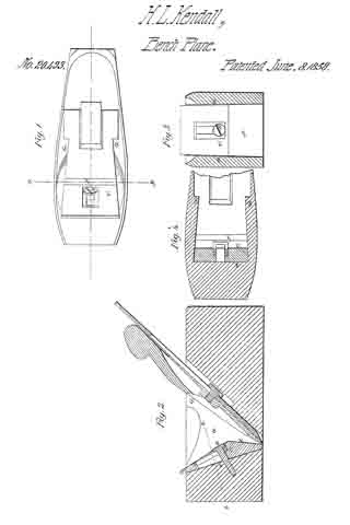
Be it known that l, BENJAMIN A. BLANDIN, of Charlestown, in the county of Middlesex, and State of Massachusetts, have invented an Improvement in Bench-Planes; and I do hereby declare that the following, taken in connection with the drawings which accompany and form part of this specification, is a description of my invention sufficient to enable those skilled in the art to practise it.
The invention relates to the manner of securing and supporting a plane-iron in position, with reference to provision for adjusting the angle of the bit or cutter-iron or its extent of cutting action. ln certain bench-planes new in the market, having provision for clamping the iron in the stock by means of a clamp-lever, (as is shown, for instance, in United States Patents Nos. 20,615 and 21,311,) the iron is supported on a movable or rocking bed-piece pivoted to the stock at some distance above the mouth of the cutter, said bed-piece having a horizontal arm extending rearwards from it, through which arm a stationary vertical screw passes, upon which a nut works, so that when the cutter is clamped in position by the clamp-lever, the position or angle of the cutting edge of the bit may be adjusted to regulate the cut of the bit or the protrusion of the cutting edge from the face of the plane. The construction embraced in such tipping-bed, and in its connection with the plane-stock, is expensive, and the bed itself, not being supported below the pivots, trembles, and causes the cutting edge to chatter when the plane is being used. To cheapen the construction, and to so apply the bed that it is at all times supported directly above or adjacent to the mouth, are the objects of my invention, which invention consists in applying, in combination with the device by which the iron is clamped in the stock, a tipping or rocking bed-piece, the lower end of which is made convex on its under surface, such convexity resting in a cylindrical or concave depression or socket-seat in the stock, and the upper surface (at such lower end) having a plane face upon which the iron or cutter is supported, the rear end of the cutter straddling a screw, upon which the adjusting nut works, so that by screwing down said nut such rear end is depressed, tipping the lower end in its seat or socket, so as to diminish and regulate the angle and bite of the cutting edge of the iron.
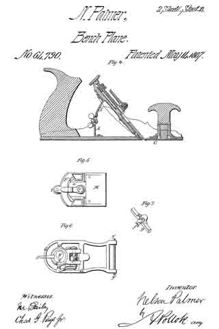
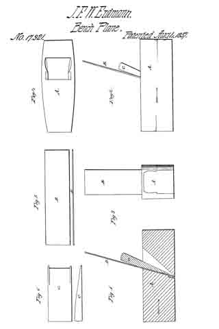
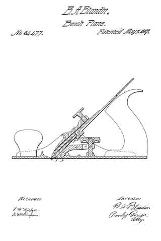
The drawing represents a central section of a benclnplane embodying the invention.
a denotes the stock; b, the plane-iron or cutter; c, the cap; d, the clamp-lever. The cutter at the mouth e, and when introduced into the stock, rests on the incline f, and at the upper side of the throat of the stock on stops or ways g, (one on each side.) The clamp-lever slides under fulcrum-stops h, (one on each side,) its lower end bearing upon the cap, and so that by the action of a screw, i, or other suitable device, the cutter is clamped in the stock, as will be readily understood. Just in rear of the mouth e, a convex socket or depression, k, is formed in the stock, this socket serving as a seat for a rocking bed-piece, l, the front face an of which, when the cutter is introduced, is in the plane of the face f, against which the lower end of the cutter rests. The bed l has an arm, n, extending back from it, through a bifurcation, o, of which a stationary screw, p, extends, as seen in the drawings. A nut, q, works on this screw and against the arm n. When the cutter is introduced into the stock, this nut is turned back, so that the bed may be tipped in its socket to bring its face and the facefinto line, in which condition the cutting edge is protruded from the plane face for the maximum of cut desirable, and in this position the cutter is securely clamped. If now the nut q be turned down on its screw, it will bear upon the arm n, tipping or rolling the bed in its socket, and forcing the lower edge of the face in forwards, pressing up the cutting edge of the bit and lessening the cut, through all of which movement to the forcing of said edge in beyond the face of the plane, the part of the bed opposite to the bearing surface of the cutter thereupon is directly supported by the seat or socket k, such firm support being incapable of vibratory movement in itself, and preventing any vibrating or chattering movement in the cutter. The piece l is a simple casting, dropped into position when the cutter is to be introduced, requiring no fitting, and being very inexpensive, thereby rendering the construction embodying such means of adjustment very cheap, as well as very efficient and reliable.
I claim combining, with a mechanism for clamping a plane-iron in position, the rocking bed-piece l, supported and rolling in a concave seat, k, and serving to support and adjust the cutting edge of the plane-iron, substantially as set forth.
BENJN. A. BLANDIN.
Witnesses:
J. B. CROSBY,
F. GOULD.