No. 27,983 – Bench Plane (H.C. Hunt) (1860)

[paiddownloads id=”86″]27983


UNITED STATES PATENT OFFICE.

_________________

H. C. HUNT, OF OTTUMWA, IOWA.

BENCH-PLANE.

_________________

Specification of Letters Patent No. 27,983, dated April 24, 1860.

_________________

To all whom it may concern:

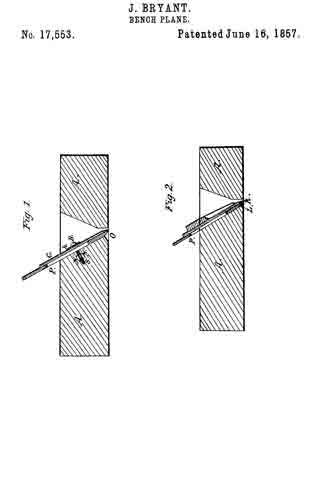
Be it known that I, H. C. HUNT, of Ottumwa, in the county of Wapello and State of Iowa, have invented a new and useful Improvement in Bench-Planes; and I do hereby declare that the following is a full and exact description thereof, reference being had to the accompanying drawings, which form a part of this specification.

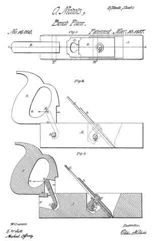
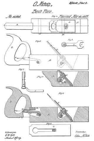
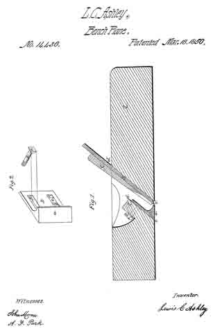
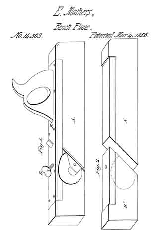
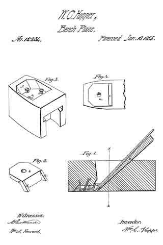
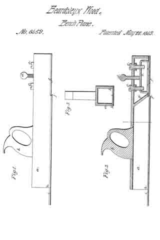
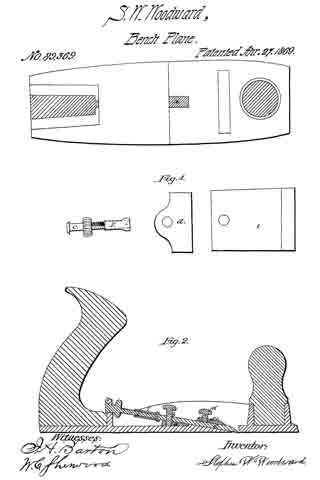
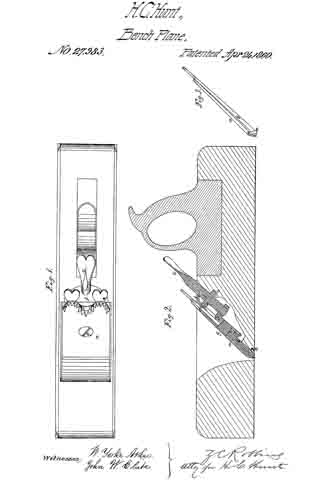
In the said drawings Figure 1, is a top view of my improved bench-plane; Fig. 2, a longitudinal section of the same, and Fig. 3, an edge view of the plane-bits detached from the stock.

The double bits a, b, in my improved bench-plane, are combined with each other, and with the plane-stock in the manner represented in Fig. 2, of the drawings, viz: the cutting bit b, has a central slit which passes from its upper end about two thirds the length thereof.

A metallic plate f, which is secured to the after side of the throat of the plane-stock, is of such a shape that it furnishes a metallic bearing surface for the cutting bit b, and also the requisite supporting and guiding bearings for the set-screw c. The screw shank of the set-screw c, is received into a screw-aperture in the angular nut d, which works in a slot in the throat-plate f. The cutting bit b, is combined with the front bit a, and also with the angular screw-nut d, by means of the screw g, which passes, first, through an aperture in the front bit a, then through the slit in the cutting bit, and then into the screw-aperture in the nut d. It will therefore be perceived that while the two bits a, and b, can be simultaneously moved outward or inward by turning the set-screw c, the cutting bit can also be readily adjusted so as to cause its cutting edge to project any desired distance beyond the closely embracing lower end of the front it, a.

It is well known that the cutting edge of a plane bit is more dulled and injured by the reverse movement of the plane over the surface of a board, than it is during its forward movement; which injurious action I have succeeded in entirely preventing by means of an attachment to the bits of my improved plane which I will now proceed to describe. A protecting metallic strap e, whose turned-up extremities are pivoted to the edges of the lower end of the front bit a, loosely embrace the lower end of the cutting bit b, so that when the plane is shoved forward, the said strap will swing freely upward into a notch which is formed in the plane-stock for its reception; but when a rearward movement is imparted to the plane, the said metallic strap will be drawn outward to a position that will cause it to elevate the front portion of the plane-stock a sufhcient distance above the face of the board that it may be operating upon, to prevent the cutting-bit from touching the surface of the board during the said reverse movement of the plane.

Having thus fully described my improved bench-plane, what I claim therein as new and desire to secure by Letters Patent, is —

Combining the metallic swinging strap e, with the bits of said plane substantially in the manner and for the purpose herein set forth.

The above specification of my improvement in bench-planes, signed and witnessed this 6th day of Feb., 1860.

H. C. HUNT.

Witnesses:
JAMES S. HARLAN,
ALBERT BALDWIN.

No. 17,657 – Bench Plane (Thomas D. Worrall) (1857)

[paiddownloads id=”47″]17657


UNITED STATES PATENT OFFICE.

_________________

THOMAS D. WORRALL, OF LOWELL, MASSACHUSETTS, ASSIGNOR TO HIMSELF AND THOMAS F. CALDICOTT, ASSIGNORS TO THOMAS F. CALDICOTT, OF CHARLESTOWN, MASSACHUSETTS.

PLANE FOR FINISHING GROOVES IN PATTERNS &c.

_________________

Specification of Letters Patent No. 17,657, dated June 23, 1857.

_________________

To all whom it may concern:

Be it known that I, THOMAS D. WORRALL, of Lowell, in the county of Middlesex and State of Massachusetts, have invented an Improved Bench Plane or Jointer; and I do hereby declare that the same is fully described and represented in the following specification and the accompanying drawings, of which —

Figure 1 is a top view of the same. Fig 2 a side elevation o it. Fig. 3 a vertical, central, and longitudinal section of it. Fig. 4 a horizontal section of its cutter holder and clamp.

In these drawings A denotes the body or stock of the plane as made of wood and having a handle B projecting upward from it, such part A generally being about one-half or less than one-half the thickness of stocks for bench planes or jointers as ordinarily made. The said stock is provided with a separate metallic cutter holder C, which is placed on its top and fastened to it by means of screws as seen at a, a. This cutter holder formed as shown in the drawings, is furnished with a slide clamp D, made so as to embrace a dovetailed projection ln, extending from the rear side of the cutter or plane iron E, as shown in the drawings. Such slide is provided with a slot f, for the reception of wedges F, G, which act against one another, the rear end of the slot and a shoulder c formed in the cutter holder. By driving up these wedges the cutter is drawn firmly down upon its seat d, formed in the holder and does not depend on the wood of the plane iron to enable it to be held in place.

By my construction of the plane important advantages are gained. It may be made lighter than ordinary planes of the kind ; its cutter is more firmly held in position ; its devices for clamping the cutter are compact and disposed in convenient positions for the carpenter to operate them as occasion may require. Furthermore, they are well protected both by the handle and the cutter so as not to be liable to be disturbed or disarranged except as occasion may require.

What I claim is —

The improved manufacture of carpenter’s bench plane or jointer as made with its handle, its wooden stock to which said handle is atlixed, and a separate metallic cutter holder, and cutter clamping devices arranged together substantially as specified.
In testimony whereof I have hereunto set my signature.

THOS. D. WORRALL.

Witnesses:
J. C. DOWNING,
JOHN E. CRANE.

No. 16,889 – Carpenter’s Plane (M.B. Tidey) (1857)

[paiddownloads id=”38″]16889


UNITED STATES PATENT OFFICE.

_________________

M. B. TIDEY, OF ITHACA, NEW YORK.

CARPENTER’S PLANE.

_________________

Specification of Letters Patent No. 16,889, dated DMarch 24, 1857.

_________________

To all whom it may concern:

Be it known that I, M. B. TIDEY, of Ithaca, in the county of Tompkins and State of New York, have invented a new and Improved Mode of Constructing Bench-Planes; and I do hereby declare that the following is a full and clear description of the same, reference being had to the accompanying drawings, forming part of this specification, in which —

Figure 1 is a View of the cavity or throat opening of the plane stock as constructed for the reception of the bit-case. Fig. 2 is a reverse view of the same and Fig. 3 is a longitudinal sectional view thereof. Fig. 4; is a bit-case to be applied to said cavity and Fig. 5 is a view of the lower extremity thereof. Fig. 6 is the same as Fig. 1 with the bit-case applied, and Fig. 7 is a reverse view of the same. Fig. 8 is a view of the plane complete as invented and constructed by me.

Similar letters of reference indicate corresponding parts in these several figures.

The object of this invention is, first to simplify the manufacturing of planes; second to render them more durable; third to retain a uniform mouth; fourth to obviate their clogging and fifth the retention of the essential part of the plane when the stock is worn out.

The following description will enable those skilled in the art to make and use my invention.

The mode of my invention consists in the construction of planes of wood and in the usual way with the exception of the cavity or throat opening which is essentially different as will be seen hereafter.

I construct in the plane stock a cavity of uniform width as denoted by lines a, Figs. 1, 2, 6, 7, and 8, which terminates longitudinally at lines 5, Figs. 1, 2, 3, 6, 7, and 8. Fig. 1 is an upper view of said cavity showing also the adjustable screw B with supporting nut C and screw holes f, f, also finishing cuts c, c. Fig. 2 is a reverse view of the same showing the face of the plane. The lines F, F, F, F, Fig. 3, represents the back face and the lower part of the front face of the cavity or throat opening and are to be made parallel with each other or nearly so, the object of which is to prevent any space or opening at point D, Fig. 7, by drawing up the bit-case for the purpose of refacing the plane. In the cavity as thus constructed I apply the metallic bit-case (Fig. 4) as seen at A, Fig. 6, which is secured thereto by screws d d through slots e, e, entering nut f, said nut being a rod of iron passing through the plane stock for that purpose. The bit-case passes through the stock, its lower extremity constituting a section of the plane’s face being provided with a mouth q and other formations necessary to the reception of the bit and its means of fastening thereto. The bit-case I arrange so as to be adjusted according to the wear or diminution of the plane’s face, for which purpose I throw the upper extremity of the case back making a projection at right angles with its bed A, which is provided with recess g, which is received by groove h, of adjustable screw B, by the operation of which the bit-case may be set at pleasure, slots e e, Figs. 4 and 6, admitting its passage under screw heads d, d, when loosened.

What I claim as my invention and desire to secure by Letters Patent is:

The application to the cavity of the plane stock of a metallic bit-case and so applying it that its lower extremity shall constitute a part of the plane’s face constructed and operated substantially for the purpose and in the way set forth.

M. B. TIDEY.

Witnesses:
WM. ANGLE,
WM. F. PECK.

No. 16,805 – Carpenter’s Plane (Oldin Nichols) (1857)

[paiddownloads id=”37″]16805


UNITED STATES PATENT OFFICE.

_________________

OLDIN NICHOLS, OF LOWELL, MASSACHUSETTS.

CARPENTER’S PLANE.

_________________

Specification of Letters Patent No. 16,805, dated March 10, 1857.

_________________

To all whom it may concern:

Be it known that I, OLDIN NICHOLS, of Lowell, in the county of Middlesex and Commonwealth of Massachusetts, have invented a useful and novel Changeable Multiform Plane; and I hereby declare that the following specification, in connection with the accompanying drawings and references thereon, constitute, embody, and designate a clear, lucid, and exact description of the construction, application, and use of the same.

In explanation of the accompanying drawings and for reference thereto, Figure 1, denotes a plan or top view of the plane stock with the iron, and handle secured thereto, the handle being secured to the top of the plane. Fig. 2, denotes a side elevation of the same. Fig. 3, is a longitudinal and vertical section of it, on line A, B, Fig. 1. Fig. 4, is a plan of my plane with the handle attached, in its lowest position. Fig. 5, denotes a side elevation of the same. Fig. 6, is a longitudinal and vertical section of the same on line C, D, Fig. 4. Fig. 7 is a plan removed from the plane stock, of the cam shafts H and L, for holding both the plane iron and handle to the plane stock, and with the wrench for operating this cam, and for screwing the cap to the plane iron connected to, or placed on the cam shaft. Fig. 8, is a plan of this wrench. Fig. 9, denotes a plan of the plane iron C removed from the plane stock, with a section of the hook headed bolt E therein showing this bolt slabbed on each side to prevent turning when the cap D, is screwed to the iron C by the wrench I. Fig. 10, is a section of the plane stock A with a plate seen at gf intervening between the hook E and cam H.

Invention — The nature of my invention consists in firmly connecting the plane iron to the cap by means of a hook headed bolt and two nuts thereon, and the arrangement of a cam shaft to act on this hook by means of a wrench or its equivalent in such manner as to securely hold the plane iron to the stock, and the intermediation of a plate between the surface of the cam shaft and hook, which would otherwise come together to hold the plane iron to the stock, and the application of substantially the same arrangement to the handle whereby one handle will answer for any number of planes or molding tools, and the variable position of this handle which can be changed on the same, to be nearly as low as the face of the plane, to operate it with the greatest ease or in securing it to the top of the plane for planing floors or any desired work, all as hereinafter set forth.

Construction — To enable persons which are efficiently skilled in the art to which my invention appertains, to construct and carry out the same, I will describe it as follows:

I construct a plane stock as seen at A, in Figs. 1, 2, 3, 4, 5, 6, and 10, of the drawing, I then construct the plane iron seen at C Figs. 1, 2, 3, 4, 5, 6, 9, and 10, and the cap seen at D, same figures, and secure them together by a hook headed bolt seen at E Figs. 1, 2, 3, 6, 9 and 10, on which is placed two nuts, one top of the cap seen at F, Figs. 1, 3, 4, 6, and 10, and the other one under the plane iron seen at G Figs. 3, 6 and 10, these nuts are both properly threaded to the bolt E, the top one F, is to firmly hold the cap D to the iron C, and the lower one G, is to adjust the position of the surface or face a, Figs. 3, 6, and 10, of the hook headed bolt E, any desired distance from the iron C, in order to be in the proper position to be acted upon to hold the plane iron to the stock by the cam seen at H, Figs. 1, 2, 3, 4, 5, 6, 7, 3, and 10, which is fitted to the plane stock A, by first forming a hole therein for this cam shaft to freely turn in, the cam shaft H is constructed by turning an iron arbor round and smooth, and forming one of its ends square, on which to place the wrench I Figs. 7 and 8, so as to turn this cam shaft, to tighten and hold the iron to the stock by bringing the surface e, Figs. 3, 6, and 10, of this shaft H in contact with, and against the surface a, of the hook headed bolt E.

A portion of the cam shaft H, is removed leaving a vacant place seen at i, Figs. 3, 6, 7, and 10, so that by turning this cam shaft around so as to bring this vacant place i opposite or nearest the face a, of the hook E, the plane iron will be liberated so that it may be removed from the plane stock, for sharpening or any desired purpose.

It is designed to turn the cam shaft H, so as to bring its surface e, against the surface a, of the hook, in the position seen at Figs. 3, and 6, and 10, in order to hold the plane iron sufliciently firm to the plane stock, while this iron can be driven down to take a rank shaving, or driven up to take a lighter shaving as may be desired by the operator, without altering the tension of the iron to the plane stock.

A plan of the cam shaft H is shown in Fig. 7, disconnected from the plane stock, to better illustrate the part removed leaving a vacant place seen at i, for liberating the plane iron from the stock; an edge view of the wrench I, is also shown connected to this shaft H, in Fig. 7, and a plan of it is shown at Fig. 8, the large end J being fitted to turn either of the nuts F or G, for the purposes before stated i, e, for holding the cap D, to the plane iron C, and for adjusting the hook surface a, of the bolt, to be correctly operated upon by the cam shaft H, to hold the plane iron firmly to the stock.

At Fig. 10 is seen a plate g, held to the stock A, by the screw y, this plate intervenes between the surface e, of the cam shaft H, and the surface a, of the hook E, to prevent wear of these surfaces, and to prevent the plane iron from sliding, or moving when it is tightened to the stock. Single plane irons can be secured to the plane stock in precisely the same manner every way as the double iron; the hook headed bolt may be as much shorter for the single iron than it is in the double one, as the thickness of the cap D, which will be readily understood.

I construct one plane handle seen at B Figs. 1, 2, 3, 4, 5 and 6, so as to answer for a whole set of planes, or for any number of planes and molding tools by shaping its front edge as seen at n, and m Figs. Q, 3, 5 and 6, so that the surface n, of the handle B can be placed on the top or higher surface of the plane A, as seen at Figs. 2 and 3, the hook K Figs. 2 and 3, 5 and 6, swinging free on the pin , Figs. 3, 4, 5 and 6, in the slot P, Figs. 3 and 6, the surface k, of the hook K, is operated upon (after being placed in the mortise M) by the surface h, of the cam shaft L, to hold the plane handle firmly to the stock, by turning the cam shaft L with the same wrench I, that is used to operate the cam shaft H, and nuts F and G.

The elevated position of the plane handle is designed for using the plane to finish floors of vessels or buildings and for smoothing or finishing in corners or places diflicult of approach, the distance from the center of the pin Q, in the plane handle, to the center of the cam shaft L, in the plane stock is the same whether the handle is in the elevated or lower position.

The handle B, can be instantly removed from the plane stock A, Figs. 1, 2, and 3, or equally well from any molding tool stock by placing the wrench I upon the square part of the cam shaft L and turning it back so as to bring the vacant or open part j, of the cam shaft L, nearest to the surface k, of the hook K, when the handle will be liberated and it can then be placed in the lowest position as seen at Figs. 4, 5, and 6, by placing the hook K into the mortise N, and the surface k, so that it can be operated upon by the surface h, of the cam shaft L, to firmly hold the handle B, in the lowest position seen at Figs. 5 and 6, which is the best for the easy working of the plane, by reason of the hand of the operator being thus in the lowest position possible when operating the plane and of course the hand will thus operate the plane in nearly a direct line with its face. The advantages are very great in this changeability of handle on the same plane from a higher to a lower, or from a lower to a higher position to work the plane with the great-est ease, or for convenience in working the plane in low places, or unapproachable places for the body, while the arms and hands can reach to work the plane if the handle be secured to the stock in the elevated position as seen at Figs. 1, 2, and 3, and another important advantage is my arrangement, whereby the handle can be applied to any number of either planes or molding tools, or both, thus saving much expense in first constructing the tools, and then in packing them, besides the advantage of change of position of the handle on the same plane, as above stated.

Use — In using my invention of plane, the cap D, has first to be secured to the plane iron, if the iron be a double one, by the fork J, of the wrench I, applied to the nut F, then it is placed in the plane stock A, in position to cut in the usual manner, the cam shaft H being of course turned so that its recess i, is next the surface a, of the hook-headed bolt E, then this cam shaft H, is turned so as to bring the surface e against, and in contact with the surface a, of the hook E, which will firmly hold the plane iron to the stock. When the round surface e, of the cam shaft H, is brought in contact with the surface a, of the hook E, no farther pressure will be had, if the cam shaft H, be turned farther because this surface e, is the round part of the cam shaft H, and this arrangement will allow the operator to either set, or adjust the plane iron (to give the thickness of shaving) with a hammer, or with the cam shaft H and wrench I, as he may wish.

The plate g, Fig. 10, intervenes between the surface a, of the hook E, and the surface e, of the cam shaft H, and prevents wear, and also prevents the plane iron from sliding by the friction on the hook E, caused by turning the cam shaft against it to tighten the iron to the plane stock.

For using the plane or molding tool, upon bench work the lower position of handle, seen in Figs. 4, 5, and 6, is the desirable one, as the plane will work much easier by the hand of the operator at this low point of the plane, but if floors of vessels or buildings, or other like surfaces are to be planed which are low and more difficult of access than bench work, then the higher position of the handle is desirable, as seen in Figs. 1, 2 and 3. The change of handle from one position to another is effected simply by turning the cam shaft L, back with the wrench I, sufliciently to liberate the hook handle K, then remove this handle and place it in the lower position, with the hook K, so that the cam shaft L, can be turned by the wrench I to tighten the plane handle in the desired position.

What I claim, is —

1. Connecting the cap D, to the plane iron C, by the hook headed bolt E with two nuts F, and G, thereon to hold them together, and then securing the iron to the plane stock A, by a cam shaft H operating upon this same hook headed bolt, which is so adjustable as to be lengthened or shortened that any desired pressure may always be had, to firmly hold the iron to the stock, by turning the cam shaft, and still allow the plane iron to be moved in or out of the plane to cut a thick or thin shaving, without farther tightening or loosening it, these parts being arranged and operated essentially in the manner and for the purposes fully set forth.

2. I also claim the plate g, secured to the plane stock, and intervening between the surface a, of the hook E, and the surface e, of the cam shaft H, to prevent wear of the hook and cam, and also to prevent the hook E, and plane iron C from sliding back when the cam shaft H, is turned to tighten the iron to the plane stock, essentially in the manner and for the purposes fully set forth.

3. I also claim the application of one single handle B, to answer for, and be secured to a whole set or any number of plane stocks, either in the lower or elevated position, and changeable from one position to another or from one plane to another, instantly and be secured firmly thereto by means of the hook K, and cam L, or their mechanical equivalents arranged and operated essentially in the manner and for the purposes fully set forth.

OLDIN NICHOLS.

Witnesses:
JOHN S. JACQUES,
E. W. SCOTT.

No. 14,436 – Bench Plane (Lewis C. Ashley) (1856)

[paiddownloads id=”31″]14436


UNITED STATES PATENT OFFICE.

_________________

LEWIS C. ASHLEY, OF TROY, NEW YORK.

BENCH-PLANE.

_________________

Specification of Letters Patent No. 14,436, dated March 18, 1856.

_________________

To all whom it may concern:

Be it known that I, LEWIS C. ASHLEY, of Troy, in the county of Rensselaer and State of New York, have invented a new and useful Improvement in Bench-Planes; and I do hereby declare that the following is a full, clear, and exact description thereof, reference being had to the annexed drawings, making a part of this specification, in which —

Figure 1 is a longitudinal section, and Fig. 2 a drawing of the adjustable metallic throat piece, detached from the plane stock.

The same letters refer to like parts in both figures.

It is well known to persons accustomed to the use of common bench planes, that in such planes, the mouth of the throat is enlarged and rendered imperfect by the wearing away of the stock. The plane iron or bit has been made adjustable, and also an adjustable metallic throat piece has been attached to the plane iron, to remedy this defect. But I believe that these hitherto known modes of prevention are either inapplicable to bench planes as commonly constructed with wood stocks, or are attended by much inconvenience in “setting” the plane iron.

My invention consists in so combining a metallic throat piece with a plane stock, to keep the mouth of the throat of the plane perfect as the plane stock shall wear away, that the plane iron or bit can be adjusted within or removed from the plane stock without disarranging the said throat piece.

The construction is as follows: A is a common wooden plane stock, with a bit or plane iron, B, fastened by a wedge, C, as usual. The front side c, d, of the throat is made parallel with the bed c’, d’, of the plane iron, as has been sometimes done heretofore. I provide a metallic throat piece, D, and attach it firmly, in an adjustable manner, to the front side c, d, of the throat.

This I effect by means of screw bolts E, having sunken heads, e, fitting in the counter-sunk slots, f, of the throat piece, which bolts are passed through the part A’ of the stock and tightened by the nuts g; or the throat piece may be secured in any other known mode which shall hold it in an adjustable manner, firmly in place. The throat piece is set so that the back part of the face a, shall be “in line” with the face of the stock. I make the forward portion of the face a, a little higher than the back part; so that that part of the stuff to be planed which is immediately in front of the cutting edge of the bit shall be surely held down and not allowed to lift up until just as it is shaved off.

It will be observed that while the metallic throat piece is so constructed and combined with the stock that the mouth of the throat of the plane shall not be enlarged or rendered imperfect by the wearing away of the plane stock, the plane iron can be adjusted or removed from, and reset in the stock, without disturbing the irmly secured throat piece.

I do not broadly claim combining a metallic throat piece with a bench plane in such a manner that the discharging aperture for the shavings shall not be enlarged or rendered imperfect by the wearing away of the plane stock.

I claim as my invention and desire to secure by Letters Patent.

Combining a metallic throat piece with a plane stock in a manner independent of the plane iron, substantially as herein described, to keep the mouth of the throat of the plane perfect as the plane stock shall wear away.

LEWIS C. ASHLEY.

Witnesses:
JOHN MORAN,
A. F. PARK.

No. 14,423 – Plane Stock (John B. Thomas) (1856)

[paiddownloads id=”30″]14423


UNITED STATES PATENT OFFICE.

_________________

JNO. B. THOMAS, OF CINCINNATI, OHIO.

PLANE-STOCK.

_________________

Specification of Letters Patent No. 14,423, dated March 11, 1856.

_________________

To all whom it may concern:

Be it known that I, JOHN B. THOMAS, of the city of Cincinnati, in the county of Hamilton and State of Ohio, have invented a new and useful Improvement in Facing Planes with Glass for Planing Wood; and I do hereby declare that the following is a full and exact description thereof, reference being had to the accompanying drawings, forming part of this specification, and to the letters and figures of reference marked thereon.

Similar letters and figures refer to corresponding parts of the improvement.

The nature of my improvement consists in the means employed for protecting the corners of the glass facing to the plane, by inclosing it within a metal band or case, and holding the glass to the stock of the plane used for carrying the bit.

The improvement is applicable to every description of planes.

To enable others skilled in the art to make and use my improvement I will proceed to describe its construction and operation by referring direct to the accompanying drawings.

Figure A, represents a longitudinal sectional view of the improved plane. Fig. B, is a transverse sectional view of the plane. Fig. C, is a face view of the plane, showing the manner of inclosing the glass face with some metallic substance.

1, represents a case or ferrule into which the glass face 3 is poured, while in a fused or melted state. The lower part of the ferrule is made perfectly true, and placed on a plane or true surface, and the glass face 3, is then poured into it, an opening having been formed by means of a core, or other equivalent, through the glass, for the bit to pass through to the face of the plane, as represented in Fig. A. The glass is held to its place by means of projecting pins or flanges 2, cast or otherwise attached to the inside of the case 1, as represented in Figs. A, and B, thus preventing the glass face from coming out of the case or ferrule, or getting loose.

The stock 4, or upper portion of the plane is made of wood, and employed for carrying the bit 7, and wedge 6, and is connected to the glass face by means of screws 5, passing through the case or ferrule 1, at the ends and sides, as shown in the different drawings, thus firmly uniting the face and stock of the plane, and giving as perfect command over the bit as is had in the ordinary construction of planes.

The glass face will be made from 1/2 to 3/4 of an inch thick, more or less, according to the size and use to which the plane is applied, and the case or ferrule will be made sufficiently wide to firmly unite the stock 4, and face together.

The great advantage arising from the use of a glass face, is in its durability and smoothness, and the plane never becoming untrue on its face or becoming scratched by using the plane on the hardest kinds of woods. The dotted screws represented in Fig. C, extend into the stock 4, of the wood portion of the plane as before mentioned.

Another advantage from the use of my improved plane is the lessening of friction compared with those at present constructed, owing to the smooth surface the glass face will always retain.

What I claim as my improvement and desire to secure by Letters Patent, is —

The glass face 3, combined with the case or ferrule 1, or its equivalent, all substantially as, and for the purposes set forth in the foregoing specifications.

JOHN B. THOMAS.

Witnesses:
L. W. SMITH,
JOSEPH R. DICKEY.

No. 14,363 – Bench Plane (Ebenezer Mathers) (1856)

[paiddownloads id=”29″]14363


UNITED STATES PATENT OFFICE.

_________________

EBENEZER MATHERS, OF MORGANTOWN, VIRGINIA.

BENCH-PLANE.

_________________

Specification of Letters Patent No. 14,363, dated March 4, 1856.

_________________

To all whom it may concern:

Be it known that I, EBENEZER MATHERS, of the town of Morgantown, county of Monongalia, State of Virginia, have invented a new and useful Improvement in Bench-Planes; and I do hereby declare that the following is a full, clear, and exact description of the construction and operation of the same, reference being had to the accompanying drawings, making a part of this specification, with letters of reference marked thereon.

A, Figure 1, stock of the plane. B, Fig. 1, metal cap, flanged on each side, fitted flush on to the blocks A’, and B’, Fig. 2. C the bit, which is wide as the stock. Above is seen the end of the tang projecting from the bit, up through an opening in the cap made to receive it. D, Fig. 1, set screw for tightening the bit. The throat opens on the left side of the plane. Fig. 2 is a view of the blocks with the cap off, showing the slope of the cut dividing them, also the recess to receive the cap. The dotted line shows where the throat is cut out.

The advantages of this plane are, first, it is not liable to choke as there is nothing to obstruct the shavings; second, the bit may be as wide as the stock, which cannot be the case in the old form of planes. Another advantage is the great facility with which the bit can be adjusted or removed. Lastly, the blocks composing the stock can be removed when worn out and new ones substituted.

This is particularly the case with the front block which always wears out first.

What I claim as new and desire to secure by Letters Patent is —

The construction of bench planes with the stock in two pieces connected by a metal, cap, as above set forth substantially.

EBENEZER MATHERS.

Witnesses:
JOSEPH K. MATHERS,
JOHN H. SNIDER.

No. 12,787 – Bench Plane Stock (George E. Davis) (1855)

[paiddownloads id=”23″]12787


UNITED STATES PATENT OFFICE.

_________________

GEO. E. DAVIS, OF LOWELL MASSACHUSETTS.

BENCH-PLANE STOCK.

_________________

Specification of Letters Patent No. 12,787, dated May 1, 1855.

_________________

To all whom it may concern:

Be it known that I, GEORGE E. DAVIS, of Lowell, county of Middlesex and State of Massachusetts, have invented a new and useful iron plane-stock and a new method of attaching the cutting-irons to the stocks to be used by carpenters and woodworkmen generally to be used and adopted instead of the old wood plane, molding and other tools which have been heretofore used; and I hereby declare that the following is a full, clear, and exact description of the manner of making and using the same, when taken in connection with the accompanying drawings and letters of reference marked thereon, in which —

Figure 1, denotes a perspective view. Fig. 2, a longitudinal and vertical section through the center of the same.

The nature of my invention consists in constructing the main body of planes, molding tools, &c., of metal, which being very thin, presents little or no impediment to the shavings passing out as they are cut from the wood, using an iron or wood handle attached to these planes. By means of the lower portion of the plane stock thus made, the hand of the operator is very near the face of the plane when it is used and consequently equally near the face of the stock which is being dressed. And my invention further consists in securing the cutting irons to the iron or other plane or tool stock, by means of a single screw (instead of the old chip) which screw secures both the cap and the cutting iron together, and both of them to the iron tool or plane stock, and by forming a lip in the back part of the throat so as to fill it and thus give a smooth even surface to the face of the plane, all as hereafter described.

To enable others skilled in the art to make and use my invention, I will proceed to describe its construction and operation.

I construct a malleable iron plane stock as seen at A, A, of the drawings, to this stock I attach a handle which may be made of iron or wood as seen at B, and this is attached to the plane stock by the screw H. On the upper side of the plane stock I form a projection as seen at C at each side of which is formed, a projection as seen at G, so as to receive the cutting iron, which differs from all other plane irons in being constructed and attached to the plane as follows, both the cutting iron D and the cap E being secured to each other and to the plane stock G one screw as seen at F which is effected by forming an oblong slot in the cutting iron about one inch long, and wide enough to receive the screw, and through which the screw passes, this slot being for the purpose of receiving this screw, and also of allowing the cutting iron to be moved down as it wears in using, in the throat of the plane immediately back of the cutting iron, I form a lip as seen at I, so as to fill the recess caused by the bevel on the edge of the plane iron in the ordinary plane, thereby preventing its catching, and filling with portions of wood, as it is used, and presenting a smooth surface to the wood.

At J can be seen the “start” which is for the purpose of starting the iron back or upwards when desired.

To use my invention of improved plane I first set the proper edge upon the cutting iron, then place this iron into its position in the plane stock then properly place the cap in its position upon the cutting iron, and then place the screw F in its position and turn it to a bearing, by a screw driver or otherwise and the plane is ready for use.

This same description will answer for the single cutting iron, excepting the description of the cap, the use of molding tools being similar to the previous description for planes.

Having thus described my invention what I claim as my invention and wish to secure by Letters Patent, is —

The metal plane stocks having a formation of a lip I in the back part of its throat so as to fill the recess which would otherwise be below the level of the cutting irons so as to present a continuous smooth surface to the plane excepting the edge of the cutting irons and throat forward of them, for the outward passage of the shavings essentially in the manner and for the purposes set forth.

GEO. E. DAVIS.

Witnesses:
R. N. HAYDEN,
JAMES WILSON.

No. 12,234 – Bench Plane (William C. Hopper) (1855)

[paiddownloads id=”15″]12234


UNITED STATES PATENT OFFICE.

_________________

WILLIAM C. HOPPER, OF PITTSBURG, PENNSYLVANIA.

BENCH-PLANE.

_________________

Specification of Letters Patent No. 12,234, dated January 16, 1855.

_________________

To all whom it may concern:

Be it known that I, WILLIAM C. HOPPER, of Pittsburg, in the county of Allegheny and State of Pennsylvania, have invented a new and useful Improvement in Planes; and I do hereby declare that the following is a full and exact description thereof, reference being had to the annexed drawings, forming part of this specification, in which —

Figure 1, is a longitudinal sectional through the center of the plane; Fig. 2 is a perspective view of the mouth piece of my improved plane. Fig. 3, is a perspective view of a section of my plane through x. x, in Fig. 1, turned up so as to show the underside of the plane, and with the mouth piece removed. Fig. 4, is a representation of the underside or face of the plane to show the position of the mouth piece.

My invention is especially designed for planes to be used in fine work, where great smoothness of finish is required, but is also very applicable with great advantage to all kinds of planes, from the smoothing plane to the jack plane.

It consists in so arranging the parts of the plane that the chisel is placed in front of its wedge, and rests against the front shoulder in the cavity of the plane, in combination with the use of a mouth piece on the face of the plane in front of the edge of the chisel to serve as a rest for the chisel and to confine the throat of the plane.

In order to enable others skilled in the art to make and use my improved plane I will proceed to explain its construction and operation.

In the drawings a, is the mouth piece which may be constructed of iron, bone, brass, hardwood or other suitable material.

The shape of the mouth piece shown in Fig. 1, is that which I prefer, but any other shape may be adopted which will accomplish the same object, as I do not desire to confine my invention to the peculiar shape of mouth piece herein described. The mouth piece is attached to the plane by a screw s, which passes through the plate b, of the mouth piece. When set in the plane, the surface of the plate b, lies flush with the face of the plane, and rests on three wood screws s’, s’, s’, which are nicely adjusted so as to afford a firm bed for it, parallel to the face of the plane. The mouth piece is of the same width as the chisel or bit c. The two arms d, d, at either side of the mouth piece, project upward into the cavity of the plane, at the same angle to the face of the plane as that at which the chisel is to be set. These arms serve as rests for the end of the bit c.

The bit or chisel is inserted in the plane in front of the wedge e, and rests against the front shoulder, against which it is pressed by the wedge. The bit is thus held firmly in its place throughout its whole length, which prevents it having any spring, and causes it to work much more smoothly. A slight space is left between the points or edge of the bit c, and the edge of the face of the mouth piece, sufficient to allow of the passage of the chip or shaving between them into the cavity of the plane; but the mouth piece is so close to the edge of the bit as to prevent the plane ripping or splintering the wood, even in the slightest degree, which would be the case if the plane had an open throat; and this arrangement causes the plane to work so smoothly that it may be used even for planing veneers, which cannot be done at all with safety with any plane of the ordinary construction. My arrangement in combination with the use of a mouth piece also enables me to dispose with the use of a cap or double bit.

By constant use the face of a plane gradually wears away, in which case it will be necessary to sink the mouth piece lower down in the hole made for its reception. If the mouth piece were sunk down at right angles to the face of the plane, it is evident, that as the bit is set in the plane at an angle of about 45 degrees, the bit as the plane wears away would recede from the mouth piece; it would no longer rest against the arms of the mouth piece, and the throat of the plane, through which the shavings pass would become too wide. To remedy this inconvenience and enable the mouth piece to be accurately adjusted to the bit, I adopt the following arrangement: The extreme edge of the mouth piece is beveled to the same angle as that at which the bit of the plane is set, as will be seen in Fig. 1; the corresponding wall of the recess in which the mouth piece is sunk, (marked f, in Fig. 3,) is also inclined at the same angle.

When the plane requires to be refaced, the screw, s, is unscrewed, and the mouth piece is taken out. The adjusting screws, s’, s’, s’, are lowered as much as it is desired to sink the mouth piece, and the mouth piece is replaced. Now as the edge of the mouth piece which rests against the wall of its recess, as well as the wall f, itself is beveled, the mouth piece in sinking into its recess, is pushed forward toward the bit, just as far as the bit has receded, and their relative position is exactly maintained, so that the sides of the bit will rest as before against the projecting arms of the mouth piece. The screw s, is also set into the plane at an angle, so that it allows for this lateral adjustment of the mouth piece, and avoids the necessity of making a new hole for the screw s.

As I remarked before, the form of the mouth piece may be varied without altering the principle involved; the simplest form which can be used, is to screw a plate of metal, countersunk into the face of the plane, immediately in front of the edge of the bit; but this only partially accomplishes the object of my invention as it does not serve as a rest for the end of the bit, nor is it capable of so easy and accurate adjustment.

Having thus described my improvement in planes, what I claim as my invention and desire to secure by Letters Patent, is —

The constructing of planes with the chisel or bit set in front of its wedge, in combination with the use of a mouth piece, substantially in the manner and for the purposes hereinbefore described.

WM. C. HOPPER.

Witnesses:
N. B. KENASTON,
WM. N. HOWARD.

No. 8,503 – Bench Hand Plane (Benjamin F. Bee) (1851)

[paiddownloads id=”7″]8503


UNITED STATES PATENT OFFICE.

_________________

BENJAMIN F. BEE, OF HARWICH, MASSACHUSETTS.

PLANE FOR FINISHING GROOVES IN PATTERNS &c.

_________________

Specification of Letters Patent No. 8,503, dated November 11, 1851.

_________________

To all whom it may concern:

Be it known that I, BENJAMIN F. BEE, of Harwich, in the county of Barnstable, in the State of Massachusetts, have invented a new and Improved Mode of Confining and Adjusting the Irons of Carpenters’ Planes and Molding Tools; and I do hereby declare that the following is an exact description thereof, reference being had to the accompanying drawings, and to the letters of reference marked thereon.

The nature of my invention consists in introducing upon each side, in the throat of carpenters planes — (in molding tools in the center of throat) a metallic plate movable perpendicularly to the plane of the iron or cap: the two plates being connected by a metallic bar on which pressure may be produced by a lever, containing an adjusting screw acting upon the principle of the cam, by which screw the pressure upon the iron may be increased or diminished :– the foregoing apparatus to be used in connection with a set screw placed at the back of the iron, the head of the screw working in a slot near the top of the iron by which the iron may be adjusted with ease and delicacy, and retained in its position after adjustment.

To enable others skilled in the art to make and use my invention, I will proceed to describe its construction and operation:

I construct my plane in any of the known forms, with the exception of removing from the throat, that portion of wood usually left for obtaining the action of the wedge upon the iron. I introduce on each side of the throat, into grooves adapted to the purpose, a metallic plate as shown at A, in the accompanying drawings. These plates are perforated near the upper edge by a rectangular hole, through which by means of an oblong mortise leading from the side of the plane stock, I place a metallic bar B, of such length as to reach to the outside of each plate, and of such strength as to sustain the amount of pressure necessary, to confine the iron firmly to the stock. This pressure I produce by the lever C, turning upon the pin D, as a fulcrum, containing the set screw E, acting on the principle of the cam; by which the pressure may be graduated at the will of the operator, according to the circumstances of the several parts.

In molding tools but one of these plates are necessary, the screw E, acting directly upon the upper edge of the plate A. When the rectangular bar B, and the pin D, have been put in their respective places they are retained there, and kept from exposure by a metallic plate, or disk, secured to the stock by screws or otherwise.

In connection with the aforesaid apparatus, I use the set screw F, working in the nut G, placed at the back of the iron; the head of this screw being of such size and shape, as to project through a slot H, near the upper end of the iron, by means of which the iron I may be adjusted to any degree of rankness, and retained in its position after such adjustment.

Whenever the operator would remove the iron from the stock, for the purpose of sharpening, clearing, or whatever else; he places his thumb upon the knob K, by drawing which toward the fulcrum of the lever, the sliding catch L, is released from the dog M; the iron is then liable to be withdrawn, by raising the upper end, so as to clear it of the set screw F. The iron may be returned to its place by a counter process, and confined there by pressing upon the knob K, in such a manner, as to force the catch L, under the dog M; retaining the same degree of rankness as before removal, abating whatever may have been whetted or ground away, and susceptible of any subsequent adjustment by means of the set screw F.

What I claim as my invention, and derise to secure by Letters Patent; is —

The application to carpenters’ planes, and molding tools, of a new method of confining the iron, by a metallic apparatus, acting upon the principles of the lever and cam; in combination with the set screw for adjusting the same, as herein described; using for the purpose, the aforesaid contrivance or arrangement of parts, or any other substantially the same, and which will produce the same effects in like manner.

BENJAMIN F. BEE.

Witnesses:
WM. H. UNDERWOOD,
STEPHEN C. ELLIS.

No. 6,459 – Bench Plane (Charles S. Beardsley) (1849)

[paiddownloads id=”3″]6459


UNITED STATES PATENT OFFICE.

_________________

C. S. BEARDSLEY, OF AUBURN, AND S. WOOD, OF NEW YORK, N. Y.

BENCH PLANE.

_________________

Specification of Letters Patent No. 6,459, dated May 22,1849.

_________________

To all whom it may concern:

Be it known that we, CHARLES S. BEARDSLEY, of Auburn, in the county of Cayuga, and SIMEON WOOD, of the city, county, and State of New York, have invented new and useful Improvements in Hand and Bench Planes, and that the following is a full, clear, and exact description of the principle or character which distinguishes them from all other things before known, and of the manner of making, constructing, and using the same, reference being had to the accompanying drawings, making part of this specification, in which —

Figure 1 is a side elevation of a hand plane on our improved plan; Fig. 2, a longi-tudinal vertical section; and Fig. 3, a cross section.

The same letters indicate like parts in all the figures.

In the hand plane as heretofore and now universally used the entire surface is on the same level, and the bit or cutting edge projects beyond it to the extent of the thickness of the shaving intended to be cut, the consequence of this is that the forward part of the surface of the plane can rest on the surface of the board forward of the shaving for that constitutes the gage to determine the thickness of shaving to be cut; but back of the cutting edge the surface of the board is reduced below the level of the forward part to the extent of the thickness of the shaving cut while the surface of the plane back of the cutting edge is on the same level with the forward part, and therefore if the back part of the plane be borne down it must be depressed and only rest on the planed surface at the back edge instead of along its entire length. The rear part, which runs on the planed surface, should be the guide to direct the plane, and for this purpose should have its whole surface running on the board and the forward part should only act as a gage and should therefore be on a higher level; but with the construction of the common plane this is not possible for the reasons mentioned.

The object of our invention is to avoid the defect of the common plane, and to this end the nature of the iirst part of our invention consists in making the surface of the plane from the cutting edge back on a level with the cutting edge, and the surface forward of the cutting edge parallel with the rear part, but movable and adjustable that it may be set so much above the level of the rear part as to determine the thickness of the shaving to be cut and constitute a gage for this purpose, and thus permit the entire surface of the plane back of the cutting edge to rest and run on the planed surface while the forward part or gage runs on the part from which the shaving has not been cut. And our invention also consists in making one surface of the planing bit or cutter the rear part of the surface of the plane, when this is combined with the making of the rear part of the stock, from the throat of the plane to the back, hollow for the passage and discharge of the shavings.

In the accompanying drawings (a) represents the stock of the plane which is made of iron and hollow. It is provided at top with a handle (b) in the usual manner, and the forward part is provided with these screws (c, c) and (d), the two (c, c) are tapped into a projection (e) of a gage plate (f) so that by the turning of these screws the gage plate will be elevated, and the other screw (d) is tapped into the stock and its end bears on the top of the projection (e)
for the purpose of forcing it down. In this way the gage plate can be regulated and set with accuracy. The side edges of the gage plate are adapted to slide freely and accurately within the hollow stock, and the rear edge which should be made at right angles with the sides of the stock, is so formed as to constitute, when in place, the continuation of a partition plate or flanch (g) which connects the two sides of the stock, and the rear face of this partition or flanch is inclined back toward the rear of the stock and gradually looses itself in the top plate of the stock which then runs horizontally to the back end. This forms what takes the place of the forward face of the throat of the ordinary plane.

The sides (h, h) of the hollow stock, inside and near the lower edge are grooved to receive the plane bit or cutter (i) which is a flat plate of metal, with the lower face perfectly true and parallel with the face of the gage plate while its upper face is parallel with the under face except at the forward end (j) where it is beveled down to form the cutting edge. This bit or cutter is thus inserted by sliding it in the grooves of the stock until the cutting edge is brought so near the rear edge of the gage plate as to form the throat of the plane for the passage of the shavings. In this way the throat is formed by the rear edge of the gage plate the flanch and the bevel of the bit or cutter, and the continuation of this throat for the delivery of the shavings at the rear is formed by the hollow stock. The lower edges of the sides of the stock should be chamfered off slightly in an upward direction at the sides of the cutting end of the bit, and then run to the forward end so much above the level of the face of the plane as to be above the greatest height to which the gage plate may be set for the greatest thickness of shaving. The under face of the gage plate should be parallel with the face of the plane back of the cutting edge but this is not indispensable. The planing bit may be inserted in the stock in any other manner as this does not constitute an essential part of our invention, and so of the gage plate it may be connected with the stock in any other desired manner, as for instance, it may be provided with projections at the sides fitted to slide in inclined grooves in the cheeks of the stock, and provided with a set screw to move toward or from the cutting edge of the bit, the inclination of the grooves having the effect to depress or elevate it while at the same time it reduces or increases the size of the throat.

The first part of our invention may be applied without the second by making the surface back of the cutting edge a part of the stock and inserting a separate bit, which may be done either by making a mortise through the sides or cheeks of the stock, or by inserting the bit and making the throat in the usual manner.

It will be obvious to those acquainted with the art of making and using planes that our improvements are applicabie to all kinds of hand planes for plain and ornamental work, the same construction and arrangement being applicable to all varieties, and the variations required being simply in the form.

We claim:

Constructing and applying the bit or cutter, substantially as described, that its lower surface may constitute that part of the surface of the plane back of the cutting edge, in combination with the hollow stock for the passage and delivery of shavings, substantially as described.

CHARLES S. BEARDSLEY.
SIMEON WOOD.

Witnesses:
A. P. BROWN, Sr.,
A. E. PETERS.

No. 17,553 – Stock For Bench Planes (Joel Bryant) (1857)

[paiddownloads id=”44″]17553


UNITED STATES PATENT OFFICE.

_________________

JOEL BRYANT, OF BROOKLYN, NEW YORK.

STOCK FOR BENCH-PLANES.

_________________

Specification of Letters Patent No. 17,553, dated June 16, 1857.

_________________

To all whom it may concern:

Be it known that I, JOEL BRYANT, of the city of Brooklyn, in the county of Kings and State of New York, have invented an Improvement in Bench or Carpenters’ Planes: and I hereby declare that the following is a full and correct description thereof, to wit:

The nature of my invention consists in removing the recess, back of the plane iron — formed by the lower edge or tip of the plane stock, and the bevel edge of the plane iron — the said recess serving no purpose whatever, but, as is well known, a troublesome annoyance in catching splinters and small pieces of wood, obstructing the use of the plane. And, also, in addition to the removal of the recess, I have invented a new and more convenient method ot securing the plane iron and its cap together (where a cap is used), and, in the plane stock, by means of a single screw bolt and a sunken nut, the said screw and nut operating in connection with the plane iron and cap, as shown in the accompanying drawings Figure 1. and by the letters and figures marked thereon and forming a part of this specification.

Fig. 1, in the accompanying drawings, is a longitudinal section of a bench plane, showing my improvement in the removal of the recess (R, Fig. 2,) as found in ordinary bench planes (Fig. 2). The recess (R, Fig. 2,) being removed by cutting off, or dispensing with the lower edge or tip (L, Fig. 2,) as far up in the stock (A,) as the upper part of the bevel of the plane iron goes to where the said plane iron (P) fits snugly to its bed in the plane stock (A) leaving in its room and stead an opening (O), having a backward inclination for the easy transit of any bits or small pieces that might pass the plane iron (P,) the said opening (O) being thus bounded on all sides by the snugly fitted plane iron (P) in the bed of the plane stock (A) it leaves no lissures or crevices in which splinters or bits of wood can fasten or stick; and thus, by this simple device, a most troublesome and vexatious annoyance is got rid of, without any inconvenience or disadvantage whatever, the said lower edge or tip (L) being of no use.

The other improvement in bench planes, is plainly shown in the said Fig. 1 by the screw bolt (B,) with its head (h) and shank (S,) in connection with the plane iron (P) and cap (C), and the sunken nut (N). The said shank (S,) being provided with a screw thread, passes through the said plane iron (P,) and cap (C) enters and fastens into the said sunken nut (N,) having a corresponding screw thread cut therein, the said screw bolt (B,) is screwed down into the said sunken nut (N,) and left with its head (h) resting upon, binding together, and firmly securing the said plane iron (P,) and cap (C,) in their place and bed in the plane stock (A), thus avoiding by this improvement the use of a wedge, or any other complicated contrivance for securing the plane iron and cap together and in the plane stock, thereby saving expense in the construction of plane stocks, and gaining an advantage and convenience in adjusting and securing plane irons over any other contrivance hitherto known or used.

I am aware that metal plane stocks have been invented with an iron tip for filling the said recess which I remove. I am also aware that an invention exists for securing the plane iron and its cap together and afterward, in the plane stock, by means of a “hook headed bolt, two nuts, and a cam shaft,” but these are essentially different from my invention; therefore, disclaiming all and every other alleged iinprovement in bench planes, (unless substantially the same as is herein set forth and described as my invention,) I institute my claim for what I desire to secure by Letters Patent as follows, to wit:

I claim the construction and use ot bench planes having an opening with a backward inclination made by the dispensing with, or the removal of the lower edge or tip of the plane stock ( as existing in bench planes of ordinary construction), the said opening being made for the purpose of avoiding the annoyance produced by splinters or small pieces of wood fastening into the recess, as formed by the said lower edge or lip of the plane stock and the bevel of the plane iron (in common bench planes) substantially as herein described and for the purpose set forth.

JOEL BRYANT.

Witnesses:
A. H. BIGELOW,
MELVILLE BRYANT.

No. 98,305 – Whalebone Shaving Plane (James A. Sevey) (1869)

[paiddownloads id=”53″]98305


UNITED STATES PATENT OFFICE.


JAMES A. SEVEY, OF BOSTON, MASSACHUSETTS.

Letters Patent No. 98,305, dated December 28, 1869.
_________________

IMPROVEMENT IN PLANE FOR SHAVING WHALEBONE.

_________________

The Schedule referred to in these Letters Patent and making part of the same.

_________________

To all persons to whom these presents may come:

Be it known that I, JAMES A. SEVEY, of Boston, in the county of Suffolk, and State of Massachusetts, have invented a new and useful or Improved Machine or Implement for Stripping or Shaving Whalebone ; and I do hereby declare the same to be fully described in the following specification, and represented in the accompanying drawings, of which —

Figure 1 denotes a perspective view of it :
Figure 2, a verticle and longitudinal section ; and
Figure 3, a transverse section of it.

In such drawings —

E denotes a plane-stock, made of wood, or other proper material, and provided with a handle, a, which extends from it in manner as exibited in figs. 1 and 2.

At or near its heel, the said stock is rebated entirely across it, as shown at b c d, in fig. 2, and also in fig. 1.

Within the recess or rebate, I arrange, at suitable distances apart, and parallel to each other, two metallic blocks or plane-iron supporters A A, they being rebated on their inner edges, as shown at e e, in fig. 3, in order to receive and support a plane-iron or cutter, C, the bevel f of whose cutting-edge, is arranged upward, or in a manner as shown in fig. 2.

The plane-iron C is held to these supporters A A by means of clamp-screws g g, screwed into the supporters, and arranged, with reference to the plane-iron, in manner as represented.

Each supporter is held in place by three screws, S S P, two of which go through the supporter and screw into the plane-stock. The third screw, P, is arranged between the screws S S, and is screwed through the plane-stock, and against the supporter, the whole being as shown in fig. 2.

By means of these adjusting-screws S S P, the inclination or bevel of the knife or plane-iron can be so adjusted as to bring the cutting-edge thereof down to a plane, L L, which extends from the lower edge of the front end of a plate-spring, M, to the lower edges of the four screws g g.

In advance of the plane-iron C there is a spring-plate or throat-piece M, which is secured to the plane-stock E by means of two screws, B B, which go through slots h h, (made in the plate M,) and screw into the stock.

Furthermore, certain adjusting-screws, D D D, screw down through the stock E, and against the upper surface of the plate M. These screws, with the screws BB, and the slots h h, are to adjust the elastic throat-piece M, or enable it to be perfectly adjusted with reference to the cutting-edge of the plane-iron C.

The implement is to be used in the manner of a common carpenter’s plane, the spring-plate M being first properly adjusted, with reference to the cutting-edge of the plane-iron, so as to cause such edge, when forced against the end of a slab of whalebone, to strike it at the requisite depth.

As soon as the plane-iron enters the slab, the incline f will raise the shaving or part to be split, or force it up from the part below it, so as to split it therefrom.

The spring-plate or throat-piece, operating in conjunction with the knife-edge of the plane f, will not only yield, so as to allow the plane-iron to hit the end of the lab at the proper depth, but will afterward press upon the upper surface of the portion to be removed, and hold the whole down to the bench.

The implement, on being moved forward, will separate a strip of even thickness from the slab, however irregular the slab may be on its upper surface.

I am aware of the plane described in the United States patent, No. 50,947, dated November 14, 1865, and granted to Harrison Ogborn, and I make no claim thereto. My plane differs from it, in having its cutter C sustained by two adjustable supporters A A, which answer not only as means of holding the cutter, but as guides for the shaving, to direct it properly through and out the plane.

My plane also has the elastic throat-piece M. provided with adjustments, by which it can be adjusted both laterally and longitudinally, with respect to the edge of the plane-iron C ; whereas, the throat-piece of Ogborn’s plane is inelastic, and adjustable only laterally, or up and down.

The elastic or spring throat-piece M does not project over the plane-iron, but is arranged in front of it, and with its working end in the same plane with the cutting-edge of the knife C.

In order for the knife C to cut, the throat-piece M must first spring upward, and, while the shaving is being cut, the throat-piece is borne down on it by the inherent elastic force of the throat-piece, the same enabling very thin, and smooth, and even shavings to be removed from the whalebone. Consequently,

What I claim as my invention is as follows :

The combination and arrangement of the spring or elastic throat-piece M, (provided with adjusting-devices, as described,) with the plane-stock E, and the cutter or plane-iron C.

Also, the combination and arrangement of the plane-iron supporters A A, and the clamp-screws g, and adjusting-screws S S P, with the plane-stock E, the cutter C, and the mouth-piece M, provided with devices for adjusting it, as set forth.

J. A. SEVEY.

Witnesses:
R. H. EDDY,
F. P. HALE, Jr.

No. 89,369 – Low Angle Bench Plane (Stephen W. Woodward) (1869)

[paiddownloads id=”52″]89369


UNITED STATES PATENT OFFICE.


STEPHEN W. WOODWARD, OF BUFFALO, NEW YORK.

Letters Patent No. 89,369, dated April 27, 1869; antedated April 16, 1869.
_________________

IMPROVEMENTS IN PLANE FOR CARPENTERS’ USE.

_________________

The Schedule referred to in these Letters Patent and making part of the same.

_________________

To all whom it may concern:

Be it known that I, STEPHEN W. WOODWARD, of the city of Buffalo, in the county of Erie, and State of New York, have invented certain new and useful Improvements in Planes for Carpenters’, Joiners’, or Cabinet-Makers’ Use ; and do hereby declare the following to be full, clear, and exact description there-of, reference being had to the accompanying drawings, and to the letters of reference marked thereon.

The nature of my invention consists in the manner of placing the plane-iron with its face downward, holding the cutting-edge of the same firmly in any required position, and elevating or lowering, forcing outward or withdrawing the same, by means of screws and pins.

In order to enable others skilled in the art to make and use my invention, I will now proceed to describe its construction and operation, referring to the annexed drawings, which form a part of this specification, and in which —

Figure 1 is a dissected view of the plane, and
Figure 2 is a sectional view of the same.

Fig. 1 represents a cast-iron plane, with a slot marked a cast in the body of the plane, for the purpose of guiding and holding a screw marked b, the operation of which screw is intended to elevate or depress the cutting-edge of the plane-iron, at the same time opening and closing the throat of the plane, so as to gauge the thickness of the shaving or cut.

C represents a thumb-screw attached to the plane-iron, for the purpose of forcing outward, withdrawing, and at the same time assisting to hold in any required position, the cutting-edge of the plane-iron.

This screw C enters the sleeve I, which is hinged or pivoted in such a manner to the rear end of the plane-bit E, that said end may be adjusted vertically without affecting the screw.

The screw C not being cramped by the movement of the rear end of the plane-bit, is left free to act upon said bit, for giving it an endwise adjustment at any angle it may assume.

d represents the cap, with screw d, holding the plane-iron firmly in its place.

This cap is caught beneath two pins, or lugs J, on the inner faces of the flanges, forming the sides of the plane, and with its screw d, serves to press down and hold in position the forward end of the same bit.

Having thus fully described my invention,
What I claim as new, and desire to secure by Letters Patent, is —

The sleeve I, provided with jaws, and pivoted to the bit E, arranged with the screws C and b, to operate as set forth.

STEPHEN W. WOODWARD.

Witnesses:
J. H. BARTON,
W. C. SHERWOOD.

No. 81,795 – Bench Plane For Cutting Blind-Slats (Carl Kupfer) (1868)

[paiddownloads id=”51″]81795


United States Patent Office.


CARL KUPFER, OF MADISON, WISCONSIN, ASSIGNOR TO HIMSELF AND KUND
J. FLEISCHER, OF SAME PLACE.

Letters Patent No. 81,795, dated September 1, 1868.

IMPROVEMENT IN PLANES FOR CUTTING BLIND-SLATS.

_________________

Specification of Letters Patent No. 81,795 dated July 4, 1854.

_________________

The Schedule referred to in these Letters Patent and making part of the same.

_________________

TO ALL WHOM IT MAY CONCERN:

Be it known that I, CARL KUPFER, of Madison in the county of Dane, and State of Wisconsin, have made new and useful Improvements in Slat-Cutting Machinery ; and I do hereby declare the following to be a full, clear, and exact description of the nature, construction, and operation of the same, sufficient to enable one skilled in the art to which it appertains to construct and use the same, reference being had to the accompanying drawings, which are made part of this specification, and in which —

Figure 1 is a perspective view.
Figure 2 is an end sectional view.
Figure 3 is an enlarged side sectional view.
Figure 4 is a side sectional view.

The invention consists in the construction of a knife or plane bit, whose edge or edges are so shaped, arranged, and combined as to cut the top, sides and bottom of the slat at one stroke of the plane across the stick of timber from which the slat is to be cut, and in leaving a straight edge or side, against which the shoulder of the plane is brought, and which serves as a guide for the plane in cutting each succeeding slat.

The bit A is made of a piece of steel, of suitable dimensions for the size of the slat to be cut, with its lower cutting-end, B, bent to an angle of forty-five degrees, or thereabouts, from the line of the body of the bit, and projecting downwards, as shown at B, fig 4. This projection is pierced with a hole, as at C, fig. 2, of any desired shape for the slat, and in line with the face of the plane D, as shown at C, fig. 2; the upper and lower edges of the aperture being brought to sharp cutting-edges, as at 1 2, fig. 2.

In sharpening these edges, care must be taken to leave two lips, whose edges, 3 4, fig. 2, are at right angles with the upper and lower cutting-edges 1 2. The bit A is set in a plane-stock, D, and secured in the ordinary manner with a wedge, E, there being sufficient throat, F, for the escape of all shavings. The front end of the plane-stock is provided with a handle, G, to facilitate holding the tool firmly.

By the use of this tool I am enabled to avoid the use of sawed lumber of any kind, and, instead, use timber as it is split from the log, like fire-wood, or without splitting at all, and thus I save from one-half to nine-tenths of the timber, and consequently a large proportion of the cash outlay formerly paid for stock.

Having described my invention, what I claim, and desire to secure by Letters Patent, is —

1. The bit A, when constructed with sharpened upper and lower edges, 1 and 2, leaving two lips, 3 and 4, said lips to be at right angles with the upper and lower cutting-edges, substantially as and for the purpose set forth.

2. The combination of the bit A, as described and claimed, with the plane-stock, for the use and purposes specified.

CARL KUPFER.

Witnesses:
J. C. SCHELTE,
A. JURGENS.