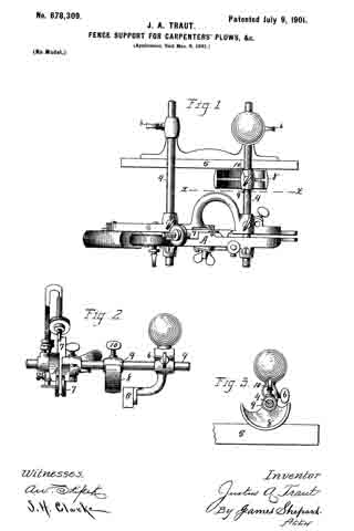
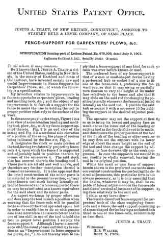
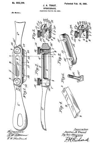
No. 719,062 – Plane (Justus A. Traut) (1903)
UNITED STATES PATENT OFFICE.
_________________
JUSTUS A. TRAUT, OF NEW BRITAIN, CONNECTICUT, ASSIGNOR TO
THE STANLEY RULE & LEVEL COMPANY, OF NEW BRITAIN, CONNECTICUT,
A CORPORATION OF CONNECTICUT.
PLANE.
_________________
SPECIFICATION forming part of Letters Patent No. 719,062, dated January 27, 1903.
Application filed October 29, 1902. Serial No. 129,227. (No model.)
_________________
To all whom it may concern:
Be it known that I, JUSTUS A. TRAUT, a citizen of the United States, residing at New Britain, in the county of Hartford, State of Connecticut, have invented certain new and useful Improvements in Planes, of which the following is a full, clear, and exact description.
This invention relates to planes, and particularly to plane-handles.
The object of this invention is to provide a detachable handle which is adjustable and which may be applied to a plane at the side thereof in any desired position, so that when the plane is used upon its side the operator may have a convenient and effective means to hold the plane and apply to it power suficient to cause it to operate efficiently and in the intended manner. Heretofore in using a plane in this manner with the edge of the knife placed vertically it has been not only extremely awkward for the operator, but very difficult to keep the plane in the proper position to get true and effective work. Frequently the thing to be planed is of such shape or is so located that it cannot be placed upright to permit the plane to be used in the ordinary way with the fixed handle upright, and it is because on occasions it is necessary to use the plane on its side that a detachable side handle is found to be a feature of great convenience and utility. Inasmuch as planes vary substantially in size, I have devised a simple and effective mechanism the purpose of which is to render the handle adjustable, so that it may be attached to planes within a wide range of sizes.
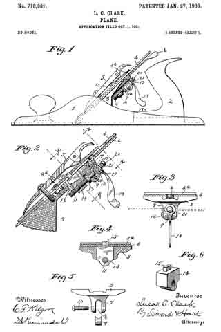
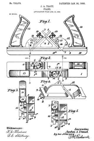
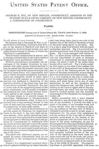
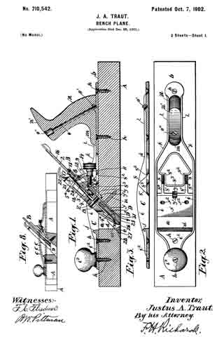
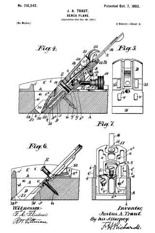
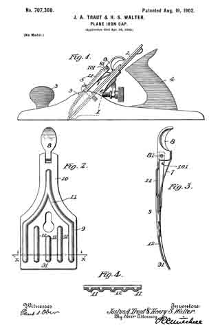
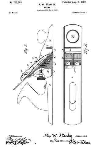
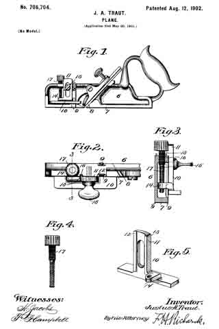
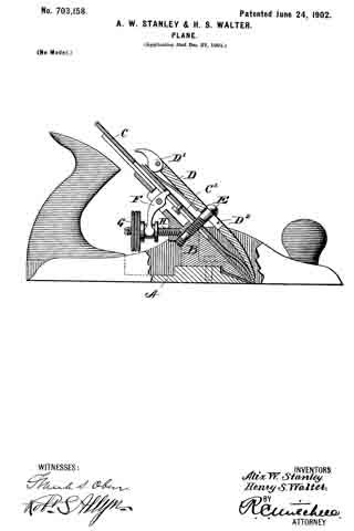
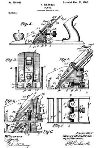
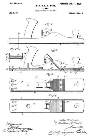
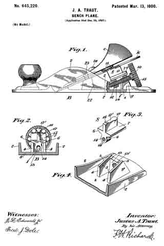
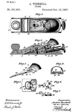
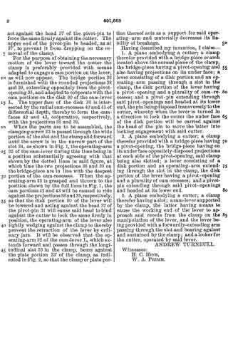
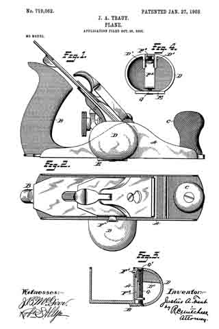
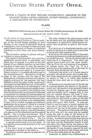
In the drawings, Figure 1 is a side elevation of a plane with the detachable handle applied thereto. Fig. 2 is a plan view thereof. Fig. 3 is a cross-section of the plane-stock and detachable handle as shown in Fig. 1. Fig. 4 is a view of the inside of the detachable handle.
A represents the stock of an iron plane. B is a handle permanently attached to the rear end thereof.
C is a front knob or handle, also usually permanently attached to the stock A.
In ordinary use the operator grasps the two handles B C.
The other details of the plane proper, such as the knife and the adjusting devices, it is unnecessary to describe in detail herein, because they constitute no part of this invention.
D is the body of a detachable handle, preferably in the form of a shell, since it provides a strong and light construction.
E is a lip on one side of the body D, the same being by preference of sufficient length to give a long flat bearing. Obviously the number of these lips E is immaterial. Two short lips spaced apart would give the same results. The lip E will for convenience of expression be termed herein the “flat” lip. F’ is a hooked lip at the opposite side of the body D, the said hook facing the flat lip E.
Ordinarily the stock A of a metal plane is provided with cheek-pieces, one on each side, and these cheek-pieces are generally shaped as shown in Fig. 1, in which they incline upwardly from each end to a high point or crown.
In attaching the haudle-body D the flat lip E is placed against the bottom of the plane-stock, and the handle is then pushed forward toward the highest part of the cheek-piece until the hooked lip F’ engages with it and may be wedged thereon, the hook F’ overstanding the upper edge of the cheek-piece and securing the handle in place on the side of the plane. The operator may then use the plane with one or both hands. In case one hand is used the palm is placed against the rear side of the body D and the fingers are placed over the top of the plane, giving a secure grip. The position of the plane will then be on its side, and the same may be pushed along the side or edge of the thing to be planed and the work done with ease and accuracy. In case the operator desires to use two hands he may grasp the solid handle B with one hand and the detachable handle D with the other, the latter taking the place of the knob-handle C. When the work is completed, the handle D may be easily removed by sliding the same backward and freeing the hook F’ from the cheek-piece of the stock.
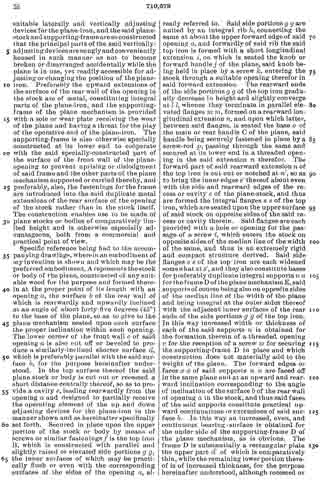
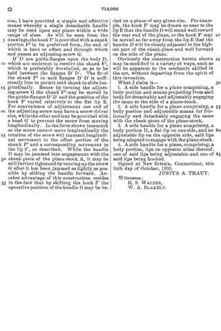
Inasmuch as planes vary substantially in size, I have provided a simple and effective means whereby a single detachable handle may be used upon any plane within a wide range of sizes. As will be seen from the drawings, the book F’ is provided with a shank portion F2 in its preferred form, the end of which is bent or offset and through which end passes an adjusting-screw G.
D’ D’ are guide-flanges upon the body D, which are undercut to receive the shank F2, which is preferably dovetaiied, so as to be held between the flanges D’ D’. The fit of the shank F2 in said flanges D’ D’ is sufficiently free to permit said shank to slide longitudinally. Hence by turning the adjusting-screw G the shank F2 may be moved in the guide-flanges D’ D’ and the position of the hook F’ varied relatively to the flat lip E. For convenience of adjustment one end of the adjusting-screw may have a screw-driver slot, while the other end may be provided with a head G’ to prevent the screw from moving longitudinally. In the form shown inasmuch as the screw cannot move longitudinally the rotation of the screw will transmit longitudinal movement to the offset portion of the shank F2 and a corresponding movement in the lip F’, as described. While the handle D may be jammed into engagement with the cheek-piece of the plane-stock A, it may be still further tightened by turning up the screw G after it has been jammed as tightly as possible by sliding the handle forward. Another advantage of this construction resides in the fact that by shifting the hook F’ the operative position of the handle D may be varied on a plane of any given size. For example, the hook F’ may be drawn so near to the lip E that the handle D will stand well toward the rear end of the plane, or the hook F’ may be moved so far away from the lip E that the handle D will lie closely adjacent to the highest part of the cheek-piece and well forward on the side of the plane.
Obviously the construction herein shown may be modified in a variety of ways, such as will be apparent to the mechanic skilled in the art, without departing from the spirit of this invention.
What I claim is —
1. A side handle for a plane comprising, a body portion and means projecting from said body for detachably and adjustably engaging the same at the side of a plane-stock.
2. A side handle for a plane comprising, a body portion and adjustable means for frictionally and detachably engaging the same with the cheek-piece of the plane-stock.
3. A side handle for a plane comprising, a body portion D, a flat lip on one side, and an adjustable lip on the opposite side, said lips being adapted to engage with the plane-stock.
4. A side handle for a plane, comprising, a body portion, lips on opposite sides thereof, one of said lips being adjustable and one of said lips being hooked.
Signed at New Britain, Connecticut, this 24th day of October, 1902.
JUSTUS A. TRAUT.
Witnesses:
H. S. WALTER,
W. A. BLAKELY.