No. 80,917 – Improvement In Coopers’ Croze (Charles O. Cook) (1868)

[paiddownloads id=”139″]80917


United States Patent Office.


CHARLES O. COOK, OF ROCKFORD, ILLINOIS, ASIGNOR TO HIMSELF AND R. R. BLAISDELL.

Letters Patent No. 80,917, dated August 11, 1868.
_________________

IMPROVEMENT IN COOPERS’ CROZE.

_________________

The Schedule referred to in these Letters Patent and making part of the same.

_________________

TO ALL WHOM IT MAY CONCERN:

Be it known that I, CHARLES O. COOK, of Rockford, in the county of Winnebago, and State of Illinois, have invented a new and improved Coopers’ Croze; and I do hereby declare that the following is a full and exact description of the same, reference being had to the accompanying drawings, and to the letters of reference marked thereon.

This invention relates to certain improvements in coopers’ croze, and consists in a simple construction of the cutting-iron, whereby it is readily attached to and detached from the adjusting-screw when desired, and yet is securely held when in use, as will be described hereinafter.

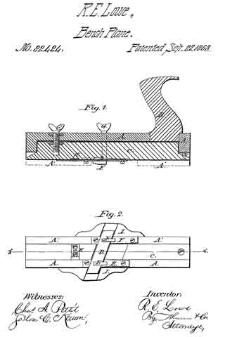
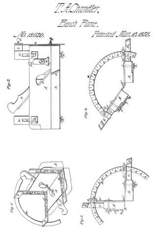
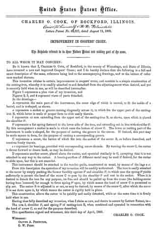
Figure 1 represents a plan view of my invention, and
Figures 2, 3, and 4 represent views of parts detached.

In the drawings —

A represents the main part of the instrurncnt, the outer edge of which is curved, to dt the inside of a barrel, and is V-shaped, as shown.

a represents a socket or groove running diagonally across it, in which iits the upper part of the cutting-iron B, which latter is made of proper form to slide easily therein.

b represents an arm extending from the upper end of the cutting-iron B, as shown, upon which is placed the shoulder b1.

b2 represents a flat spring fastened to the lower side of the iron, and extending out in line with shoulder b1.

By this arrangement a socket is made in which rests the button of screw C. The lower or cutting part of the instrument is made V-shaped, for the purpose of cutting the groove in the staves. If desired, this part may be made square in forrn, for the purpose of cutting a corresponding groove.

C represents a screw, the button of which its into the socket of the cutter B, as before described, and revolves freely therein.

c c represent its bearings, provided with corresponding screw-threads. By turning the screw C, the cutter is thrust forward or drawn back, as may be desired.

D represents another screw, placed above the cutter, and operated sirnilarly to C, excepting that it is not attached in any way to the cutter. A bearing-surface of different metal may be used if desired, for the cutter to slide upon, but this is not essential.

This instrument should be attached to the wooden guide, constructed as usual, by means of the lugs x x.

From this description the operation of my invention will be readily understood. The iron is easily attached to the screw by simply pushing the former forcibly against b2 and shoulder b1, in which case the spring b2 yields sufficiently to permit the head of the screw C to pass by the shoulder b1 and rest in the socket. When it is desired to detach the iron for any purpose, its free end should be pulled up from the croze (the holding-screw having been loosened) far enough to force spring b2 open, by which means the head of screw C is permitted to slip out. The cutter B is adjusted in or out, as may be desired, by means of the screw C, after which the screw D is set down upon it, by which means the cutter is rigidly held in place.

This construction allows the cutter to be quickly and easily detached, while at the same time it is firmly held when in use.

Having thus fully described my invention, what I claim as new, and desire to secure by Letters Patent, is —

The arm b, shoulder b1, and spring b2 of cutting-iron B, when combined and operated in connection with the head of screw C, as and for the purpose described.

This specification signed and witnessed, this third day of April, 1868.

CHARLES O. COOK.

Witnesses :
OLIVER A. PENNOYER,
G. W. FORD.

No. 82,424 – Improvement In Planes For Cutting Blind-Slats (R.E. Lowe) (1868)

[paiddownloads id=”145″]82424


UNITED STATES PATENT OFFICE.

_________________

R. E. LOWE, OF UPPER ALTON, ILLINOIS.

IMPROVEMENT IN PLANES FOR CUTTING BLIND-SLATS.

_________________

Specification forming part of Letters Patent No. 82,424, dated September 22, 1868.

_________________

To all whom it may concern:

Be it known that I, R. E. LOWE, of Upper Alton, in the county of Madison and State of Illinois, have invented a new and Improved Rustic-Blind-Slat Plane; and I do hereby declare that the following is a full, clear, and exact description of the construction and operation of the same, reference being had to the accompanying drawings, making a part of this specification, in which —

Figure 1 is a longitudinal vertical section through line x x of Fig. 2. Fig. 2 is a bottom view.

The object of this invention is to construct a simple and easily-adjustable instrument, by which the slats of which rustic window-blinds are made can be out out from the wood in an easy and expeditious manner. The instrument is so improved that the slats can be cut of different widths and thicknesses, while, if the plane becomes dull, it can be made to present a sharp edge again in a moment of time, without the necessity of removing it to be ground or sharpened.

In the drawings, A A’ is the stock; B, the handle, and C an adjustable shoe, held at the rear end by a screw, c, and held and adjusted at or near the forward end by a larger and stronger set-screw, c’, provided with a thumb piece or nut on the upper side of the stock. This shoe does not extend across the whole width ofthe sole of the stock, but lies in a groove or longitudinal depression in the latter, as seen in the bottom view, Fig. 2. The part A represents the body of the stock, A A’ representing a projecting flange along its left lower edge, which operates against the side or edge of the stick from which the slats are cut, and serves to guide the instrument.

D is the bit or cutter-iron, lying obliquely across the sole in a flat position upon two supporting-plates, E E, which are screwed to the stock, and itself being firmly held in position by two hooks, F F, the shanks of which pass through the stock and enter the screw-nuts G G on its upper side, just in front of the handle. The supporting-plates E E rest upon the stock, and neither they, nor the cutter-iron, nor the hooks F F are connected in any way with the shoe C, which lies under the cutter, as shown in Fig. 2. In consequence of this arrangement, when the shoe is adjusted up or down by means of the set-screw c’, the thickness of the slat that the iron will cut is perfectly controlled and regulated thereby. Strips of rubber may be placed under the ends of the bit, between it and the wood, to hold it more firmly. The width of the track between the projecting flange A’ and the opposite projecting hook F, between which the stick that is operated upon must be held, is such that a wide slat may be cut; or, by means of a splitting-gage, H, one or two narrow ones may be made.

In practical operation I usually construct the instrument so that it will, without the gage, cut a strip of one inch in width, or, with the gage, will cut two strips of half an inch each. Were the bit only of sufficient length to cut one strip, without the possibility of shifting it endwise, so as to bring anew cutting-edge or an unused portion of the same cutting-edge into operation when one part of the edge becomes dull, the workman would be obliged to take out the bit and sharpen it every time it lost its edge. I obviate this difficulty by making it of such length that it can be shifted endwise in either direction, so as to bring a fresh portion of the edge into operation. Practically I construct it so that it will cut a one-half inch strip at its center, and, when dull there, can be shifted half an inch either to right or to left. Its edge will hold without grinding, therefore, three times as long as if of the usual form.

In order to support and guard the projecting ends of the cutter-iron, I attach guards I I to the side of the stock, their under edge flush with the sole of the stock, and a groove or depression sunk obliquely across them to allow the longitudinal movement of the cutter-iron.

Having thus described my invention, what I claim as new, and desire to secure by Letters Patent, is —

1. The arrangement of the shoe G, stock A A’, screws c c’, cutter-iron D, and clamping-hooks and nuts F G, substantially as described, when the parts are constructed to operate in the manner set forth.

2. The arrangement of the guards I I with the knife D, the track C, and the gage H, constructed and operating substantially as described.

R. E. LOWE.

Witnesses :
C. W. LEVERETT,
J. B. HOVEY.

No. 82,450 – Improvement In Carpenters’ Planes (John Blake Tarr) (1868)

[paiddownloads id=”146″]82450


United States Patent Office.


JOHN BLAKE TARR, OF CHICAGO, ILLINOIS.

Letters Patent No. 82,450, dated December 18, 1868.
_________________

IMPROVEMENT IN CARPENTERS’ PLANES.

_________________

The Schedule referred to in these Letters Patent and making part of the same.

_________________

TO ALL WHOM IT MAY CONCERN:

Be it known that I, JOHN BLAKE TARR, of Chicago, Cook county, State of Illinois, have invented an Improved Carpenters’ Plane; and I do hereby declare that the following is a full, clear, and exact description thereof, reference being had to the accompanying drawings, making part of this specification, in which —

Figure 1 is a longitudinal section, taken vertically through the centre of my improved plane.
Figure 2 is a similar view of the same parts, showing the plane-iron set to cut a very thick shaving.
Figure 3 is a perspective view of the plane complete.

Similar letters of reference indicate corresponding parts in the several figures.

This invention relates to an improvement in adjusting and setting plane-irons of carpenters’ or bench-planes, of various descriptions, whereby these irons or blades can be adjusted and set at any desired pitch for removing very thin or very thick shavings, by simply turning a thumb-screw, which is applied to the plane-stock and blade in such manner as to give a greater or less bow or bend to the latter, according to the pitch required, as will be hereinafter described.

Before my invention, plane-irons have been applied to plane-stocks by means of clamping-devices, which bent or bowed the irons, so as to increase or diminish the pitch of their cutting-edges for removing thick or thin shavings. The objection to said devices is, that it is necessary to render the plane-irons comparatively loose in adjusting their cutting-edges for removing thick shavings. The object of my invention is, to so construct and apply adjusting-clamps to plane-irons and their stocks, that the greater the amount of pitch given to the cutting-edges of the irons, the tighter will they be held, as will be hereinafter described.

To enable others skilled in the art to understand my invention, I will describe its construction and operation.

In the accompanying drawings —

A represents the stock of a jointing-plane, having my invention applied to it. This stock is constructed in the usual well-known manner, and is also in the blade or plane-iron B, as will be seen by reference to figs. 1 and 2.

Near the upper termination of the inclined bed a of the plane-stock, a recess is made, into which is fitted and firmly secured a plate, b, having a deep notch or slot formed in it, which should be exactly in the centre of the width of the stock.

In rear of this slotted plate b, and in a line therewith, a hole is bored into the plane-stock, and screw-tapped for receiving a male-screw, C, which has a T-head formed upon its upper end. A similar T-head screw, D, is tapped into the plane-stock in front of the slotted plate b. Both screws, C and D, are in the same vertical plane, and both have the same degree of inclination backward, as shown in figs. 1 and 2. The screw C projects from the top of the plane-stock, and the screw D projects from the inclined bed a of this stock. They are arranged about equal distances from the slotted plate b, and may be adjusted further into or out of the stock at pleasure, by turning them to the right or left.

A thumb-screw, E, is tapped through a sliding nut, F, applied to the plane-iron B, which screw has an annular groove formed in it near that end which is opposite its head. This groove leaves a contracted neck, which is received by the groove or notch in the upper edge of fixed plate b, as shown in figs. 1 and 2, thus affording a purchase for the screw E, when applied in its place.

The nut F has grooves in its sides, at right angles to the axis of the screw E, which grooves receive the inner edges of the plane-iron B, when the nut is applied in the slot thereof, and thus afford an attachment for the nut to the plane-iron.

The heads on the screws C and D are turned so as to bring them in line with the length of the slot through the plane-iron.

The nut F, with screw E applied to it, is slipped upon the plane-iron, and the latter adjusted in place in the plane, so that the neck of the screw E will be received by the slot or notch on plate b, and the screws C D passed through the plane-iron slot, as shown in the drawings. The screws C and D are then turned around so as to leave their heads cross-wise of the slot through the plane-iron, thereby causing them to serve as bearings against wliich the plane-iron is pressed upward, by tightening the screw E.

It will be seen, from the above description, that the plane-iron is forced upward and forward against the lower edges of the heads of screws C D, by means of an adjusting-screw, which is between said screws; consequently the degree of inclination of said plane-iron will be governed by the relative positions of the beads of said screws C D, which latter can be adjusted at pleasure, when the plane-iron is released from pressure.

It will also be seen that by setting the screw E up tight, the plane-iron will be more or less curved or bent out of a straight line, as shown in fig. 2, the result of which will be to throw back the cutting-edge of said iron and increase or diminish its pitch, and the size of the throat. By this arrangement, a very nice adjustment can be effected by simply turning the thumb-screw E, while, at the same time, the greater the pitch attained, the stronger will the plane-iron be held in place.
To remove the plane-iron for sharpening it, it is only necessary to loosen the screw E, and turn the heads of the screws C D in line with the slot through the plane-iron, when the latter may be slipped out of its place, and the screw E and its nut detached from it.

I do not claim, broadly, adjusting the cutting-edges of plane-irons by pressure applied between the upper and lower ends of the iron; but

What I do claim as my invention, and desire to secure by Letters Patent, is —

1. The combination of the central clamping and tightening-device with the adjustable supports C D, the said device and the supports being applied to a plane-stock, and in the relation to the plane-iron thereof, substantially as and for the purpose herein described.

2. Making the two supports or abutments C D adjustable, substantially as and for the purpose herein described.

3. Applying pressure to a plane-iron between two supports, C D, through a device, E F, substantially in the manner and for the purpose herein described.

4. Changing the pitch and tightening the plane-iron by the same means, and at the same time, the means employed being constructed and operated substantially as herein described.

5. The adjusting of the plane~iron by means of the clamping-device composed of the screws C, D, and E, nut F, and plate b, and applied in such manner that the bit is tightened, and the pitch changed at the same time, and by the same means, when constructed to operate substantially in the manner described.

6. Arranging the plane-iron beneath the heads or shoulders of two adjustable bearings, C D, and under a shoulder of a nut, F, so that it may be adjusted by means of either or both ofthe bearings C D, and may be tightened and have its pitch changed by the screw E, all substantially in the manner and for the purpose described.

JOHN BLAKE TARR.

Witnesses:
EDW. SCHAFER,
EDM. F. BROWN.

No. 19,620 – Joiner’s Beveling Plane (T.A. Chandler) (1858)

[paiddownloads id=”73″]19620


UNITED STATES PATENT OFFICE.

_________________

T. A. CHANDLER, OF ROCKFORD, ILLINOIS.

JOINER’S BEVELING-PLANE.

_________________

Specification of Letters Patent No. 19,620, dated March 16, 1858.

_________________

To all whom it may concern:

Be it known that I, T. A. CHANDLER, of Rockford, in the county of Winnebago and State of Illinois, have invented a new and Improved Bevel-Fillister and Rabbet-Plane Combined; and I do hereby declare that the following is a full and exact description thereof, reference being had to the accompanying drawings, in which —

Figure 1 is a perspective view; Fig. 2, a side view, and Figs. 3 and A end views. Like letters designate like parts in the several views.

The two planes A, and A’, separately considered, correspond to a rabbet plane, provided with keys B, and plane irons C, in the ordinary manner. Molding planes in some instances may be substituted. The cutter D, gage E, and set screw F, are attached to the side of the plane, in the usual way, and for the ordinary use. The two planes are connected together by the jointed slides H, and H’, Figs. 1 and 2. These slides fit into corresponding grooves or gains in the side of the planes so that the slides will be flush with the side of the planes. In the slides are elongated slots I, which receive the shank of the bolts J, which shank passes through the plane, and has a thumb screw K, on the opposite side as seen in Figs. 2 and 3. In each slide is an elongated recess or depression, which receives the bolt head as represented at L, Figs. 1 and 2. The slides being thus formed and provided with a hinge joint at H”, allows the planes to be moved to any position or angle upon the slides, and secured in place, by the bolts and thumb screws J, and K.

From the slide H”, extend two arms, L, L, in the outer ends of which are slots to receive the sector M, as shown in Figs. 1, 3, and 4. The set screws N, N, enter the slots, for the purpose of holding the sector in place, and thereby the planes, in the desired position or angle. By means of the degrees indicated on the sector, the planes may be set so as to cut at any desired angle.

The planes may be moved so as to cut at various angles, and may be reset so as to cut at any previous form of angle, by noting the degree on the sector. The planes may be set at right angles so as to have the character of a fillister plane, for cutting grooves. By extending one plane from the other, at right angles, they form a raising plane, for cutting or raising panels. By turning them at an acute angle, they become a bevel plane. By placing the planes at right angles so that the face of one plane will be level with the side of the other, similar to the position of Fig. 3, they become a halving plane. By extending one plane from the other so that one is set at an obtuse angle to the other, similar to the position of Fig. 4, they will bevel moldings for pilasters and other similar purposes. The plane may be made to cut moldings at other angles than those described, and may be set in various other positions than those described, which positions will readily be suggested in the practical operation of the plane, and will not change the nature of my invention.

By making slots in the arms of the hinges H, H, and fastening them to the plane stocks by thumb screws, so that they can be adjusted, and fastened in the position desired, the plane can be adjusted to plane flat bevels, or bevels of a small angle on boards of various thickness on both sides of the board at the same time, which cannot be done with any plane made prior to my invention.

Having described my invention so as to enable any person skilled in the art to make and use it, I claim —

Making one or both plane stocks adjustable, on the arms or shanks of the hinges, so as to plane bevels of the same angle, on boards of various thicknesses substantially as described.

THOS. A. CHANDLER.

Witnesses:
W. H. BURRIDGE,
JAMES A. BRIGGS.

No. 41,258 – Improvements In Planes For Jointing Table Leaves (T.P. Granger) (1864)

[paiddownloads id=”100″]41258


UNITED STATES PATENT OFFICE.

_________________

T. P. GRANGER, OF PECATONICA, ILLINOIS, ASSIGNOR TO HIMSELF AND JOSIAH BEST.

IMPROVEMENT IN PLANES FOR JOINTING TABLE-LEAVES.

_________________

Specification forming part of Letters Patent No. 41,258, dated January 12, 1864.

_________________

To all whom it may concern:

Be it known that I, T. P. GRANGER, of Pecatonica, in the county of Winnebago and State of Illinois, have invented new and useful Improvements in Planes for Jointing Table-Leaves; and I do hereby declare that the following is a full and complete description of the construction and operation of the same, reference being had to the accompanying drawings, making part of this specification, in which —

Figure 1 is an end View of the first plane used in forming the bed part of the joint. Fig. 2 is a face view of the same plane. Fig. 3 is an edge view of the bed-leaf after the first plane has been used upon it; and Fig. 4 is an end view of the same. The plane, Figs. 1 and 2, is so formed, as shown at A, as to cut the “round” B on the bed-leaf.

The bed-leaf is first prepared by being jointed on the lower side and edge, the guide C working against the lower side, B’, Fig. 4. A stop, C’, on the opposite side of the plane, by coming in contact with the edge of the leaf B”, determines the depth to which the plane, cuts. Planes, Figs. 5 and 6, show an end and face view of the second plane to be used upon the bed. This is for cutting away B”, Fig. 4, which has been left by the first operation. The guide D works flat against the lower side of the leaf, the groove D’ forming a stop by coming in contact with B, Fig. 3. After the planes, Figs. 5 and 6, have been used the edge of the leaf presents the appearance shown in Figs. 7 and 8. I now use the planes shown in Figs. 17 and 18, for the purpose of cutting the round B to a sharper angle with the square portion of the leaf, as shown at a b in Figs. 19 and 20. This operation finishes the bed-leaf. The fall-leaf is first prepared for making the joint by being jointed upon the under side and upon the joint edge. I then apply the plane shown in Figs. 9 and 10, the guide E working against the under side of the leaf. The face F of the plane coming in contact with the square edge of the leaf F’, determines the depth to which the groove G is cut in the edge of the leaf; but as this plane does not cut the groove G quite deep enough to fit the round B on the bed-leaf. I apply the plane shown in Figs. 13 and 14. The face H coming in contact with the edge F’, determines the depth to which this plane cuts the groove, which is shown complete at c d in Figs.15 and 16. The table-butts are now set in the usual manner, and the leaf presents the structure and adjustment shown in Figs. 21 and 22. A table joint thus constructed presents this peculiar feature, that when the leaf is down, as in Fig. 22, the inner angle of the leaf comes in contact with the under edge of the bed, as at e, and thus raises the fall-leaf higher up on the bed-leaf, as shown at e’, thereby making a better and more durable joint.

What I claim as my improvement, and desire to secure by Letters Patent, is —

The herein-described series of planes for setting table-joints, the same being constructed and used in the manner and for the purpose herein set forth.

T. P. GRANGER.

Witnesses:
A. S. VAN DYKE,
A. J. THOMPSON.

No. 53,899 – Planes For Making Blind Slats (Enoch K. Thomas And Hans H. Andresen) (1866)

[paiddownloads id=”116″]53899


UNITED STATES PATENT OFFICE.

_________________

ENOCH K. THOMAS, OF ROCK ISLAND, ILLINOIS, AND HANS H. ANDRESEN, OF DAVENPORT, IOWA.

IMPROVEMENT IN PLANES FOR MAKING BLIND-SLATS.

_________________

Specification forming part of Letters Patent No. 53,899, dated April 10, 1866.

_________________

To all whom it may concern:

Be it known that I, ENOCH K. THOMAS, of Rock Island, Rock Island county, and State of Illinois, and HANS HEINRICH ANDRESEN, of Davenport, Scott county, State of Iowa, have invented a new and useful Plane for Making Window-Shade Slats; and we do hereby declare that the following is a full, clear, and exact description thereof, reference being had to the accompanying drawings, making a part of this specification, in which —

Figure 1 is a perspective view of a single-iron slat-plane. Fig. 2 is a perspective view of the cutter or plane-iron detached from the plane-stock. Fig. 3 is a sectional view, showing the mode of cutting slats from a piece of wood. Fig. 4 is a front end view of the single iron plane. Fig. 5 is a front end view of a plane-stock which is adapted for receiving three cutters.

Similar letters of reference indicate corresponding parts in the several figures.

The object of this invention is to produce slats for wooden window-shades of a uniform thickness and width by means of a plane which is so constructed that the slats pass freely through the plane-iron between the sole of the plane-stock and its bottom cutter without liability of becoming broken or otherwise injured, as will be hereinafter described.

To enable others skilled in the art to understand Our invention, we will describe its construction and operation.

The plane which we have represented in Figs. 1, 2, 3, and 4 of the drawings is intended for cutting one slat at a time from a piece of wood. The sole of this plane has three steps, a a’ a”. The intermediate step, a, is equal in width to the width of the slats which are produced, and the vertical surface of the step a2 is intended to form a side guide for the plane-stock in its forward movements over the piece of wood from which the strips or slats are cut.

The cutter or plane-iron B has a cutting-lip, b, on its lower end and a cutting-lip, c, formed on one side — that side which is nearest the step a. This plane-iron has an opening, d, through it, which should be equal in width to the width of the slats that are cut, so that as the slats that are severed from the piece of wood by the horizontal and vertical cutting-lips b c these slats will pass freely through the plane-iron without being materially bent out of a straight line, as shown in Fig. 3.

The plane-iron B is secured at the required pitch in its stock A by means of a wedge, C, in the usual manner of securing common plane-irons into their stocks, and the cutting-lip b projects below the sole of the stock a distance which is equal to the thickness desired for the slats.

It will be necessary to form a depression, e, just in rear of the cutter lf, so as to allow of the slats rising over this cutter; but as this cutter can be made quite thin, it will not be necessary to form much of a depression in the sole of the stock.

To obviate a gouging action of the cutting-lip b, which would cause the plane to work very hard and produce slats of an uniform thickness, the space between the cutting-edge of said lip and the lower end of the wedge C should not be greater than the required thickness ofthe slats. The space back of this point for a short distance may be increased, as above mentioned.

It will be seen from the above description of our plane or slat-cutter that the slat is held firmly down upon the surface of the piece of wood during the operation of producing it, and that the only elevation of the slat from such surface takes place at the cutter b, which must pass under the slat; but while this is the case the slat which is being cut will he held down in rear of said cutter, so that it cannot be broken or split.

We do not confine our invention to a single-iron plane for cutting or producing slats, as the stock may be adapted for receiving two, three, or more cutters, arranged as shown in Fig. 5, so that a number of slats can be cut at each forward movement of the plane over the piece of stuff.

It is obvious that this plane may be secured to a bench-vise or to any other object and the stuff moved over it instead of moving the plane by hand over the fixed stuff ; or, if desirable, the plane or the stuff from which the slats are cut may be moved by machinery without changing the principle of our invention. One great advantage of our invention is that we can cut slats from the side or edge of a board or log without the necessity of resawing and previously dressing the stuff, and this can be done with stuff of any thickness or width.

Were not our cutter provided with the two cutting-edges described, the splints or slats could not be cut from a bolt or plank of a greater thickness than the length of the cutting-edge of the cutter or plane-iron. This will be evident from an inspection of the drawings illustrating our mode of cutting strips or splints from a large bolt or log.

By arranging a series of cutters on a plane-stock, stepped as shown, we can, after having cut a series of splints from the bolt, bring two cutters into use, and after we have cut another series of splints by each of the two cutters we can bring into use a third cutter in connection with the two which are already brought into use, and so on, according to the number of steps and cutters provided on the plane-stock. To bring the different cutters into use a channel in the wood must be made tbr a succeeding cutter by a preceding cutter, as must be evident. Thus by our invention a series of splints may be cut at one time from a bolt which is of much greater thickness than the length of the edge of either of the cutters after channels adapted for the respective cutters are cut in the bolt.

Having thus described our invention, what we claim as new, and desire to secure by Letters Patent, is —

1. The construction of a cutter for producing slats with two cutting-edges and an opening through the shank of the cutter for the passage ofthe slats, substantially as described.

2. The combination of one or more slat-cutters, constructed substantially as described, with a plane-stock having its sole stepped substantially as set forth.

ENOCH K. THOMAS.
HANS HEINRICH ANDRESEN.

Witnesses:
HANS ARBAHR,
HANS KÜHAER.