No. 729,725 – Guide For Planes (James W. Brady) (1903)

[paiddownloads id=”585″]729725


UNITED STATES PATENT OFFICE.

_________________

JAMES W. BRADY, OF SOUTH BEND, INDIANA.

GUIDE FOR PLANES.

_________________

SPECIFICATION forming part of Letters Patent No. 729,725, dated June 2, 1903.
Application filed June 23, 1902. Serial No. 112,775. (No model.)

_________________

To all whom it may concern:

Be it known that I, JAMES W. BRADY, a citizen of the United States, residing at South Bend, in the county of St. Joseph and State of Indiana, have invented certain new and useful Improvements in Guides for Planes; and I do hereby declare the following to be a full, clear, and exact description of the invention, such as will enable others skilled in the art to which it appertains to make and use the same.

My invention relates to improvements in that class of planes used in beveling the edges of lumber; and its object is to provide an adjustable guide capable of a lateral rectilinear movement and a rotary movement independent of such rectilinear movement, whereby an angular as well as a lateral adjustment is accomplished.

In beveling each side of a piece of timber it is often necessary to alternately change from one bevel to another, and I provide devices which may be previously set to give the required angular adjustment when the guide is reversed from one angle to the other to accurately bevel each edge of the board.

With these objects in view the invention consists in the novel construction of parts and their arrangement and aggroupment in operative combination.

I have fully illustrated the invention in the accompanying drawings, in which —

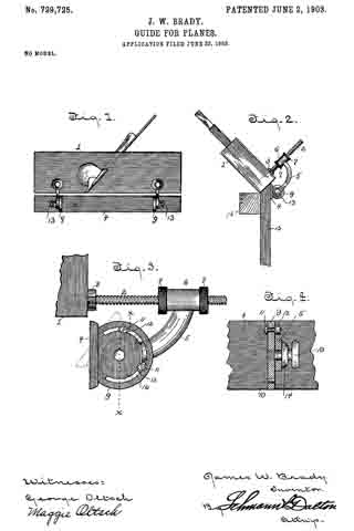
Figure 1 is a side elevation of the plane and guide. Fig. 2 is an end elevation showing the guide adjusted for beveling the edges of a board downward from its finished face. Fig. 3 is an enlarged end view of the guide. Fig. 4 is a section on the line x x of Fig. 3.

Referring to the drawings, 1 designates the plane-stock, from one side of which projects the threaded shafts 2, secured in place near the bottom in any suitable manner, but preferably screwed and held by jam-nuts 3, as shown. The guide 4 is suspended from these threaded shafts by means of downward and inwardly curved arms 5, having integral sleeves 6, which are mounted on the rods and capable of being moved back and forth thereon to provide a lateral rectilinear movement for the guide, which when adjusted to the desired position may be held by the jam-nuts 7, screwing on the shaft at each end of the sleeve. The guide-plate 4 is provided with a plurality of transverse ears 9, having a pivotal connection at their centers with the arms 5, said ears also having concentric slots 10, in which are mounted adjustable pins 11, having binding-nuts 12 fitted on their projecting ends, adapted to engage the arm 5 and limit the rotary movement of the ear when the guide-plate is augularly adjusted to plane a beveled edge on the board. The central apertures in the ears are engaged by the threaded shank of a thumb-nut 13, which is let into an aperture in the end of the arm 5, said thumb-nut having a flanged base 14: to provide a broad binding-surface on the arm.

By mounting the guide adjustably on a shaft projecting from the side of the plane-stock a horizontal rectilinear movement is provided for the guide, so that when the angular adjustment is effected by means of the thumb-nut 13 the guide-plate maybe brought in under the face of the plane to the desired distance to form a bevel on work in which the side of the board opposite the guide is provided with a cleat or other obstruction for the plane-face. Such an application of the invention is illustrated in Fig. 2, wherein a portion of a panel of a carriage-body 15, having a cleat 16, is shown, the bevel extending from the inner corner of the cleat 16. I When a double bevel is to be formed on the edge of a board, the pins 11 may be adjusted to the required distance on each side of the arm 5, so that the angular adjustment for each bevel may be alternately changed without resetting the pins, as they form stops for the guide-plate by contacting with the arm 5. One of these angular adjustments is shown in dotted lines in Fig. 3.

Having thus described my invention, what I claim is —

1. The combination with a plane-stock, of a rotary guide, a support for said guide, adjustable devices carried by the guide and adapted to engage opposite sides of the support to limit the rotary movements of the guide.

2. The combination of a plane-stock having a laterally-extended shaft, a sleeve adjustable on the shaft and provided with an arm, a guide revolubly mounted on the arm, and adjustable devices carried by the guide to regulate the rotary movements of the same.

3. In a device of the class described, the combination with the plane-stock having screw-shafts projecting laterally therefrom, sleeves slidable on said shaft, jam-nuts to hold the sleeves, arms depending from the sleeves, a guide-plate having ears pivotally connected to said arms, slots in the ears, and adjustable stops in the slots on each side of the arm, whereby two angular adjustments may be made without changing the position of the stops.

4. In a device of the class described, the combination with the plane-stock having shafts projecting laterally therefrom, of a plane-guide horizontally adjustable on said shafts and consisting of arms and a guide-plate having ears pivoted to said arms, and means carried by the ears on each side of the arms to limit the rotary movement of the guide-plate when angularly adjusted.

In testimony whereof I affix my signature in presence of two witnesses.

JAMES W. BRADY.

Witnesses:
GEORGE OLTSCH,
MAGGIE OLTSCH.

No. 426,806 – Plane (Edmund P. Hann) (1890)

[paiddownloads id=”463″]426806


UNITED STATES PATENT OFFICE.

_________________

EDMUND P. HANN, OF PORTLAND, INDIANA, ASSIGNOR OF
ONE-HALF TO WILLIAM S. BAKER, OF SAME PLACE.

PLANE.

_________________

SPECIFICATION forming part of Letters Patent No. 426,806, dated April 29, 1890.
Application filed December 14, 1889. Serial No. 333,744. (No model.)

_________________

To all whom it may concern:

Be it known that I, EDMUND P. HANN, a citizen of the United States, residing at Portland, in the county of Jay and State of Indiana, have invented certain new and useful Improvements in Planes; and I do declare the following to be a full, clear, and exact description of the invention, such as will enable others skilled in the art to which it appertains to make and use the same.

This invention has relation to an improvement in planes; and it has for its object to provide means whereby the cut may be regulated without moving the bit and without the employment of springs and levers or other like objectionable devices.

The invention will be fully understood from the following description and claims, when taken in connection with the annexed drawings, in which —

Figure 1 is a longitudinal sectional view of a plane constructed according to my invention, and Fig. 2 is a perspective view of the follower removed from the stock.

Referring to said drawings by letter, A indicates the stock, which may be mainly of any ordinary or approved construction and provided with a suitable handle B. The forward portion of the stock and in advance of the throat thereof is provided with a chamber, which is inclosed by the longitudinal side plates or walls of the stock, and also the forward transverse wall thereof. The body of the stock is provided at its forward end with a beveled seat a to seat the bit and the iron for securing the same in position.

The bit C is provided with the usual elongated slot b for adjusting the same; but, as will presently appear, such slot is only needed at first placing the bit after it has been removed for repairs or the replacement of a new one.

Secured transversely in advance of the throat d and to the side walls of the stock is a cross bar or block D, which is provided with an aperture e and serves as a bearing for one end of a cam-shaft, as will be presently explained. The forward transverse end wall f of the stock is also provided at a corresponding point with a similar aperture g to receive the forward or opposite end of said cam-shaft.

E indicates what I shall denominate the “follower.” This follower is provided with a truly planed engaging-face corresponding with the engaging-face of the main body of the stock and is arranged in the chamber or recess F. This follower may consist of a block, as shown, having a longitudinal recess in its upper face, as N, to receive the cam-shaft G, and across the opposite ends of this recess are strips i, which may be of metal or other suitable material. These strips are designed to furnish bearings for the cam-shaft, and the recess is preferably covered by a plate H or the like.

G indicates the cam-shaft. This shaft, which is designed to raise and lower the follower, has its opposite ends extended therefrom, as shown at l, and bear, respectively, in the aperture of the cross-bar D and the aperture in the forward transverse wall of the stock. These journal ends being arranged at corresponding points and eccentrically on the opposite ends of the shaft G, it will be seen that by simply turning the shaft the follower may be raised or lowered, as desired. By arranging the cam-shaft horizontally and causing it to exert its force transversely the follower can be raised or lowered evenly at all points by a single cam and without having to place any objectionable lugs or other attachments on the top or bottom of the plane-stock, and it also permits of a hand-wheel or other means of rotating it being placed on the forward end of the stock out of the way. The forward end of this shaft is provided with a small hand-wheel I for turning the same and manipulating the follower.

In operation it will be seen that when the bit has been set with respect to the lower face of the main body of the stock and it is desirable to get a cut of less depth it is simply necessary to turn the cam-shaft by the hand-wheel until the follower has been lowered to the desired point. To increase the depth of the cut the operation is simply reversed.

With a plane of this character it will be seen that there is little or no chance for lateral deviation of the cutter, as when once set it remains so, as the adjusting of the cut is performed by the follower and the manipulating cam-shaft.

While I have described minutely the parts in the exact construction and combination as illustrated, yet I do not wish to be understood as confining myself to such, as it is obvious that the object in view might be arrived at by other devices such as would suggest themselves to a skilled mechanic. It is necessary, however, that a cam and also a follower be used.

Having described my invention, what I claim is —

1. A plane having a practically fixed bit, in combination with a follower arranged in advance thereof and a rotatable cam-shaft having its axis arranged horizontally and exerting its pressure transversely thereto for raising and lowering said follower, substantially as specified.

2. The combination, with a stock having a I chamber in advance of the throat, a cam-shaft jonrnaled therein and adapted to exert pressure transversely to its axis of rotation, and carrying a hand-wheel on one end, of a follower suspended on said shaft and adapted to be raised and lowered thereby, substantially as specified.

3. The combination, with the stock, of the vertically-movable follower, the cam-shaft bearing in said follower, and bearings in the stock for receiving the opposite ends of the shaft, substantially as specified.

In testimony whereof I affix my signature in presence of two witnesses.

EDMUND P. HANN.

Witnesses:
WILLIAM S. BAKER,
DAVID V. BAKER.

No. 286,894 – Plane (Fortune L. Bailey) (1883)

[paiddownloads id=”343″]286894


UNITED STATES PATENT OFFICE.

_________________

FORTUNE L. BAILEY, OF FREEPORT, INDIANA.

PLANE.

_________________

SPECIFICATION forming part of Letters Patent No. 286,894, dated October 16, 1883.
Application filed July 12, 1883. (No model.)

_________________

To all whom it may concern:

Be it known that I, F. L. BAILEY, of Freeport, in the county of Shelby and State of Indiana, have invented certain new and useful Improvements in Planes; and I do hereby declare the following to be a full, clear, and exact description of the invention, such as will enable others skilled in the art to which it pertains to make and use it, reference being had to the accompanying drawings, which form part of this specification.

My invention relates to an improveinent in planes; and it consists, first, in the combination of the bearing-plate having the adjusting-screw swiveled thereto, the slotted bit which is attached by means of a set-screw to the plate which bears against its top, and a screw-bolt which passes through both of the plates and the bit, and which has the adjusting-screw to pass through its lower end; second, in a bit having a nut passed through its outer end, and a set-screw passed through the nut, so as to have its lower end bear against the lower plate, and thus adjust the angle at which the bit shall set, as will be more fully described hereinafter.

The object of my invention is to provide an attachment for the bits of planes, whereby the bit can be adjusted back and forth and set it at any desired angle without having to remove the bit from the plane-stock.

Figure 1 is a longitudinal vertical section of a bit embodying my improvements. Fig. 2 is an inverted view of the same.

A represents the lower or bearing plate, which has the lug B formed on the lower side of its outer end, and in which the adjusting-screw C is swiveled. This screw will be of any desired length, and is used to adjust the bit and the plate placed upon its top back, and forth in relation to the plate A. Through this plate A is made a vertical slot, D, of any desired length, and through which passes the screw-bolt E. This screw-bolt E has an enlarged perforated head upon its lower end, for the adjusting-screw to pass through, and receives a thumb screw or nut, F, upon its upper end, for the purpose of clamping the parts of the attachment tightly against the bit. The bit G also has a slot cut through it; but it need not necessarily be as wide nor as long as the one which is cut through the plate A. Through this slot is passed the bolt and the set-screw H, which secures the bit and the top plate, I, together. This top plate, I, and the bit are secured rigidly together by means of this set-screw, for the purpose of causing them to move together when the adjusting-screw is turned. The top plate may either rest solidly upon the bit, or it may be made in the form of a spring, as may be desired. Through the outer end of the bit is passed a nut or bushing, J, through which is passed the set-screw L. By means of this set-screw L the bit can be set at any desired angle in relation to the part A. Secured to the under side of the bearing-plate A is a suitable bracket, O, to rest on the top of the plane-stock when made of wood.

By means of the construction here shown and described, the bit may be adjusted back and forth without having to remove the parts from the plane.

I am aware that a slotted bit has been adjusted by means of screw-rods and nuts, which project up from the side of the body of the plane, and which rods have a connecting-plate passed over them, so as to bear against the outer end of the bit, and thus feed it forward, and this I disclaim. My invention differs from this in having the adjusting-screw swiveled directly upon the bearing-plate A, and which is made to adjust the bit by means of a screw-bolt which passes through the plate placed upon the top of the bit and the bit itself.

Having thus described my invention, I claim —

1. In a plane, the combination of the plate A, which is attached to the under side of the bit, with the inclined bracket O, which is secured to the under side of the plate, substantially as shown.

2. The combination of the bearing-plate A, which is secured to the under side of the bit G, and which plate is provided with the slot D, with the swiveled adjusting-screw C, which is attached at its outer end to the plate A, the screw-bolt E, which passes through the slots in the bit, the bit provided with the slot for the bolt to pass through, and the plate placed upon the bit, substantially as described.

3. The combination, with the bit, of a nut or bushing which is passed through its outer end, and the set-screw which is passed through the nut or bushing for the purpose of adjusting the inclination of the bit, substantially as specified.

4. The combination of the bearing-plate provided with a slot, the slotted bit, the set-screw, the plate which is placed upon the top of the bit, the screw-bolt which passes through both of the plates and the bit, the adjusting-screw for moving the bit back and forth, and the set-screw for regulating the angle at which the bit is placed, substantially as shown.

In testimony whereof I affix my signature in presence of two witnesses.

FORTUNE LEWIS BAILEY.

Witnesses:
MARCUS B. CHADWICK,
LEVI W. WHITE.

No. 182,722 – Improvement In Plane-Guides (Andrew J. Teamer) (1876)

[paiddownloads id=”269″]182722


UNITED STATES PATENT OFFICE.

_________________

ANDREW J. TEAMER, OF EVANSVILLE, INDIANA.

IMPROVEMENT IN PLANE-GUIDES.

_________________

Specification forming part of Letters Patent No. 182,722, dated September 26, 1876; application filed June 12, 1876.

_________________

To all whom it may concern:

Be it known that I, ANDREW J. TEAMER, of Evansville, Indiana, have invented certain Improvements in Plane-Guides, of which the following is a specification:

My invention relates to certain improvements in that class of planes in which an adjustable guide hung to the plane is used for determining the angle of the cut to be made by the plane-bit; and the object of my improvements is to so construct a plane of this class that the guide can be readily adjusted to any desired angle. This object l attain in the manner which I will now proceed to describe, reference being had to the accompanying drawing, in which —

Figure 1 is a side view of my improved plane and guide, and Fig. 2 a transverse vertical section of the same.

A is the plane, and B the guide, the latter being secured near each end by means of set-screws a to plates D, each of which has a projection, b, hinged by a bolt or pin, d, to ears e on a plate, F, the latter being secured by means of set-screws f to the side of the plane.

The set-screws a and f, are adapted to vertical slots g in the plates D and F, and each of these slots terminates at its upper end in an opening, i, larger in diameter than the head of the set-screw.

Each of the bolts d, by which the guide B is hung to the plane, is provided with a nut, m, on tightening which the guide may be secured to any angle in respect to the plane to which it may be adjusted. In order that this angle may be accurately determined, I make the projection b of one of the plates D of the segmental form shown in Fig. 2, and on the periphery of this segment make lettered or numbered graduations, a mark, x, on one of the ears to which the projection is hinged, indicating the angle at which the guide B is set in respect to the plane, and the bevel of the edge of the strip which is being operated upon.

In addition to the angular adjustment of the guide B, the latter may, owing to the slots g in the plate F and plates D, be adjusted vertically in respect to the plane, and, owing to the enlarged openings i at the ends of the slots, the plate F may be readily removed from one plane and attached to another, or the guide B may be removed and replaced by a new one. Instead of using a bolt, d, and nut m for clamping the plates D and F, together, as described, a screw-bolt, adapted to a thread out in one of the ears e, may be used.

It will be seen that these bolts answer the twofold purpose of hinging the two plates together, and of securing them in position after adjustment, thus avoiding the necessity of employing a separate thumb-screw in addition to the hinging-pin, as is usual.

It will be evident also that plates similar to the plates D may be substituted for the plate F, and that a plate, F, may be applied to the guide, but the construction shown is preferred.

I wish it to be understood that I do not desire to claim, broadly, a plane-guide hinged to a plane by means of adjustable plates; but I claim as my invention —

1. The combination of the hinging and clamping bolts d with the plane A and plate F, having ears e e, and with the guide B and plates D, having projection b, all substantially as described.

2. The plates D, having slots g, with enlarged openings i, in combination with the guide B and its set-screw a.

3. The combination of the guide B and the plates D, having a graduated segmental projection, b, with the plane A and the plate F, having ears e e, as and for the purpose set forth.

In testimony whereof I have signed my name to this specification in the presence of two subscribing witnesses.

ANDREW JACKSON TEAMER.

Witnesses:
JOHN BRIGGS,
A. C. ANCONA.

No. 141,828 – Improvement In Crozing And Chamfering Planes (Allen M. Strattan) (1873)

[paiddownloads id=”214″]141828


UNITED STATES PATENT OFFICE.

_________________

ALLEN M. STRATTAN, OF LADOGA, INDIANA.

IMPROVEMENT IN CROZING AND CHAMFERING PLANES.

_________________

Specification forming part of Letters Patent No. 141,828, dated August 12, 1873; application filed March 22, 1873.

_________________

To all whom it may concern:

Be it known that I, ALLEN M. STRATTAN, of Ladoga, in the county of Montgomery, Indiana, have invented an Improvement in Crozing and Chamfering Planes, of which the following is a specification:

This is an improved tool for coopers’ use, and combines the functions of a croze and a charnfering-plane.

Figure 1 is a perspective view of a tool embodying my invention. Fig. 2 is a perspective view of the same reversed. Fig. 3 is a section of my tool taken parallel with the fence-board. Fig. 4 shows my croze-bit detached.

A is a stock and B its fence-board, similar in general conformation to those of a customary chamfering-plane, C being the chamfering-bit and D the wedge. A peculiarly-shaped excavation, E F, in the stock serves as the combined throats of both the chamfering-bit C and a “crow” or crozing-bit, G, whose form is clearly shown in Fig. 4. This crozing-bit is secured by a set-screw, H, tapped into the under side of the stock, and which serves to nip the said bit by its shank I. Embedded into the convex-working face of the stock in advance of, and in line with, the croze-bit G, is a guide bar or tongue, J.

My tool is used in the common way of crozing plows,the fence-board resting upon the edge of the chine and the croze-bit, and chamfer-bit operating simultaneously to both croze and chamfer the chine.

Before using this plane the top of the vessel is leveled by the common block-plane. Then I proceed by placing the chamfering-plane on the top of the vessel, and rotating the plane forward and backward until the croze is cut to a sufficient depth. The chine is finished at the same operation.

I claim as new and of my invention —

The combination of the stock A E F, fence-board B, and bits C and G, when constructed and arranged as herein described to perform the chamfering and crozing operations simultaneously, as explained.

ALLEN M. STRATTAN.

Witnesses:
ISAAC WILLIAM ELLIS,
NATHAN STRATTAN.

No. 114,613 – Improvement In Planes (James K. P. Smith) (1871)

[paiddownloads id=”186″]114613


UNITED STATES PATENT OFFICE.

_________________

JAMES K. P. SMITH, OF JEFFERSONVILLE, INDIANA, ASSIGNOR T0 HIMSELF
AND L. S. SHULER, OF SAME PLACE.

IMPROVEMENT IN PLANES.

_________________

Specification forming part of Letters Patent No. 114,613, dated May 9, 1871.

_________________

To all whom it may concern:

Be it known that I, JAMES K. P. SMITH, of Jeffersonville, in the county of Clark and State of Indiana, have invented a new and useful Improvement in Joiners’ Planes; and I do hereby declare that the following is a full, clear, and exact description thereof, which will enable others skilled in the art to make and use the same, reference being had to the accompanying drawing, forming part of this specification.

This invention relates to improvements in joiners’ planes; and it consists in an improved arrangement of screw clamping and setting apparatus and a metal casting fitted in a socket in the wood stock behind the throat for clamping the plane-bit against, after setting, to hold it firmly, and for the support of the adjusting-screw, all as hereinafter described.

Figure 1 is a longitudinal sectional elevation of my improved plane. Fig. 2 is a longitudinal section through the casting. Fig. 3 is a perspective view of a part of the clamping apparatus.

Similar letters of reference indicate corresponding parts.

A represents two vertical plates, joined by the cross-bar B and the top plate, C. Said plates have the front ends inclined in the same angle the plane-bit D is to be set in, and these ends have rabbets E for the plane-bit to rest in at each edge. This casting is a little wider than the plane-bit, and not quite as deep as the height of the wood stock F. It is let into a deep recess, G, behind the throat H, so that the top plate, which is wider than the recess, will rest at the projecting edges on the top of the stock F to be screwed down to it.

The end of plate C toward the plane-bit has a boss, I, perpendicular to the line of the plane-bit, for the support of the adjusting-screw K, for setting the bit, which screw is fitted in a hole through said boss, and provided with a collar, L, which, together with the head of said screw, prevents end movement. This screw works in a stud, M, projecting from the back of the plane-bit, for adjusting the latter.

N represents clamping-bars, pivoted to the prongs O of a yoke, P, at the insides of said arms near the ends, to be clamped against the front side of the plane-bit for pressing the latter against the ends of plates by the clamping-screw Q, screwing through the end R of said yoke, and extending rearward through the end of the planestock, where it is provided with a thumb-bit, S, for turning the screw. The said arms O work in slots T in the ends ot’ the plates A, and extend beyond the edges ofthe plane-bit for holding the bars N against the front side. The said bars are pivoted to the arms for allowing them to bear fair upon the plane-bit.

The inner end of the screw has a bearing in the cross-bar B, which has a socket, T, made for it. The said screw, being turned by the thumb-bit S to draw the yoke toward the rear, will clamp the plane-bit firmly against the ends of the plates, as clearly shown, and being turned the other way releases it.

To remove the plane-bit the clamp is released as much as it can readily be, and the bit forced down by screw K till stud M is disengaged; then the upper end of the bit is tilted forward to clear the stud M from the lower end of screw K, when the bit may be lifted out.

Having thus described my invention, I claim as new and desire to secure by Letters Patent —

1. The combination, with the plane-bit and the wood stock, of the casting A B C, yoke P, clamps N, and clamping-screw Q, all substantially as specified.

2. The combination, with the above, of the adjusting-screw K, substantially as specified.

JAMES K. P. SMITH.

Witiiesses:
HENRY B. DIBBLE,
JNO. W. SULLIVAN.

No. 50,530 – Improvement In Bench Planes (Lyman C. Bliss) (1865)

[paiddownloads id=”108″]50530


UNITED STATES PATENT OFFICE.

_________________

LYMAN C. BLISS, OF RICHMOND, INDIANA, ASSIGNOR. TO LYMAN C. BLISS AND JOHN GRIFFITH.

IMPROVEMENT IN BENCH-PLANES.

_________________

Specification forming part of Letters Patent No. 50,530, dated October 17, 1865.

_________________

To all whom it may concern:

Be it known that I, LYMAN C. BLISS, of Richmond, in the county of Wayne and State of Indiana,have made new and useful Improvements in Bench-Planes; and I do hereby declare the following to be a full, clear, and exact description of the nature, construction, and operation of the same, sufficient to enable one skilled in the art to which it appertains to construct and use the same, reference being had to the accompanying drawings, which are made part of this specification, and in which —

Figure 1 is a View of the under side or face of the plane. Fig. 2 is a longitudinal vertical section on the line x x, Figs. 1 and 3. Fig. 3 is a transverse vertical section on the line y y, Figs. 1 and 2.

The same letters refer to corresponding parts in the different figures.

The invention consists in the adaptation to and arrangement in the tool of the jointer and slat-cutting plane.

A is the stock ofthe plane; and B,a strip which is fastened to the face of the plane, acting as a guide and separating the bits., The side C of the plane is occupied by the jointing-bit D, of ordinary construction, and the other side of the plane is faced with plates E and F, the former of which passes from the hind end of the plane to the back edge of the bit G, while the other, starting from the forward end of the plane, is partially overlapped by the oblique edge of the plane-bit G. The bit G is secured by means of a bolt, H, which passes through the slot in the rear edge of the bit and also through an orifice in the plate F, which on its rear edge is divided. The portion f of the plate, or that immediately over the longitudinal channel I in the face of the plane-stock, is cut diagonally, so as to present a yielding edge parallel with the cutting-edge of the bit, which overlaps it.

The operation is as follows: The jointing-bit D being first brought into action, the board from which the strip, splint, or slat is to be cut is straightened, when the plane is shifted so as to bring the other side into action, the sliver cut by the bit G pressing back the tongue f of the plate F, and passing out by the way of the channel I, to be discharged at the rear end ofthe plane. The splint or slat being separated from the edge of the board by the draw-cut of the bit G, leaves the said splint smoother and without cracks.

Having described my invention, what I claim therein as new, and desire to secure by Letters Patent, is —

As an article of manufacture, a bench-plane constructed, as described, with a jointing-bit and a draw-cut splint-cutting bit on the opposite sides of the dividing-strip on the face of the plane.

LYMAN O. BLISS.

Witnesses :
JOHN FINLEY,
THOS. A. DUGDALE.

No. 50,947 – Improvement In Splint Planes (Harrison Ogborn) (1865)

[paiddownloads id=”109″]13957


UNITED STATES PATENT OFFICE.

_________________

HARRISON OGBORN, OF RICHMOND, INDIANA.

IMPROVEMENT IN SPLINT-PLANES.

_________________

Specification forming part of Letters Patent No. 50,947, dated November 14, 1865.

_________________

To all whom it may concern:

Be it known that I, HARRISON OGBORN, of Richmond, in the county of Wayne and State of Indiana, have invented certain new and useful Improvements in Planes for Cutting Blind-Slats, Splints for Baskets, and other similar work; and I do hereby declare that the following is a full, clear, and exact description of the construction and operation of the same, reference being had to the annexed drawings, made a part of this specidcation, and the letters of reference thereon, the same letters referring to identical parts.

Figure 1 is a side view of the plane when arranged for use as a jack-plane, showing the bottom of the plane used for cutting slats, &c.
Fig. 2 is a longitudinal vertical section of the plane through the line y y, Fig. 4. Fig. 3 is a like section through the line x x, Fig. 4. Fig. 4 is a transverse section of the stock. Fig. 5 is a view of the knife employed for splitting the slats or splints. Fig. 6 is a view of a knife for splitting the slats with beveled edges. Fig. 7 shows the adjustable plate for determining the cut and removing splinters that wedge in the plane. Fig. 8 is a sectional view of the knife or bit used on the splint-plane. Fig. 9 is a top view of the same.

The stock of the plane A is arranged for two bits, and having two faces. One of these is an ordinary jack-plane, as shown in Figs. 1 and 2.

The handle B is adjustable, and may be made to stand perpendicularly to either of the plane-faces. It turns upon a rod, M, and, swinging in a notched recess in the corner of the stock, is held perpendicularly to either face by an ordinary window-catch, of which there are two shown, Figs. 2 and 3, G G’.

On the bottom of the face of the splint-plane are shown two adjustable guides, one square, the other beveled. One of these, according to the character of the work, is used on the left-hand side of the plane, held in place by screws with oblong heads working in slots in the ends of the guides, as shown in Fig. 1.

D is the knife or bit ofthe splint-plane, held in place by the same kind of screws working in slots, so as to allow the adjustment of the knife by the aid of the set-screws N N.

E shows the bit of the jack-plane, of ordinary construction, and arranged in the usual manner.

K is an adjustable plate, held by similar screws on the face, allowing its adjustment to the knife as they are worn away in use, to which is attached the set-screw passing through the stock and working in a collar on the upper surface of the plane. This arrangement makes it easy to withdraw the plate in case a splinter should wedge in the space between the plate and knife.

The knives H I, one straight, the other bent for cutting beveled edges, work as shown in Figs. 3 and 4. The knives are held in place by the wedge L, and the points protrude through narrow slots in the plate K. (Shown in Fig. 1.) The bent knife its the beveled point of the wedge L. When the straight knife is used the wedge goes on the right of it, but on the left side of the bent knife. There are one or more of these knives used, according to the number of slats intended to be cut from the board. The bent knife is used with the beveled guide.

In operating with this plane, the boards, being dressed, are cut into narrow strips of the proper width on their edges by the knife H, or so that the slats shall have beveled edges, by the knife I. The splints are cut by the knife or bit D passing between the plate K and the bit D. Rising over D, they are bent in a contrary direction, and passing out under the lower surface of the plane they are flattened and delivered free from curves or tendency to twist.

Having thus fully explained the character and operation of my improvements, what I claim as my invention, and seek to secure by Letters Patent, is —

1. The arrangement, in a splint-plane, of the plate K, bit D, and one or more splitting-knives, and guide C, all constructed and combined substantially as and for the purpose set forth.

2. The arrangement, in a splint-plane, of the piate K, bit D, beveled guide C and one or more bent knives, I, all constructed and combined substantially as and for the purposes set forth.

3. The combination of the plane-stock A and adjustable handle B, so constructed with the rod M and springs G and G’ as to be capable of being arranged perpendicularly to the two faces of the plane, substantially as described. In testimony whereof I have signed my name to this specifcation in the presence of two subscribing witnesses.

HARRISON OGBORN

Witnesses:
R. MASON, BEN FIELD.

No. 51,153 – Improvement In Splint Planes (James Dempsey) (1865)

[paiddownloads id=”110″]51153


UNITED STATES PATENT OFFICE.

_________________

JAMES DEMPSEY, OF RICHMOND, INDIANA.

IMPROVEMENT IN SPLINT-PLANES.

_________________

Specification forming part of Letters Patent No. 51,153, dated November 28, 1865.

_________________

To all whom it may concern:

Be it known that I, JAMES DEMPSEY, of Richmond, in the county of Wayne and State of Indiana, have invented certain new and useful Improvements in Planes for Cutting Slats for Window-Shades or other Thin Splints of Wood.

The object of my invention is to construct a splint-plane that shall be as readily adjustable as the ordinary hand-plane, and have such a channel for the splint when out as that it shall not be broken by being thrown abruptly upward over the knife. In other planes either the splint is liable to be broken or the knife placed horizontally is ditiicult of adjustment. Another object is to provide that the splint when cut shall be perfectly smooth and fit for use as it comes from the plane. Both of these objects are, I believe, accomplished by my im-provements.

To enable others skilled in the art to make and use my invention, I will describe its construction and operation, reference being had to the annexed drawings, making a part of this specification, and the lettering thereon.

In the different plans the same letters refer to identical parts.

Figure 1 is an elevation showing the half of the plane when divided into two parts, on the line x x, Fig. 3, where the plane as constructed is divided. Fig. 2 is a longitudinal section on the line x x, Fig. 3. Fig. 3 is a transverse section upon the line y y, Fig. 4. Fig. 4 is a plan of the plane, showing the bottom part, the guide being represented as cut away in part. Fig. 5 is a plan showing the construction of the bit. Fig. 6 is a plan showing the construction of the spring in the bottom of the plane.

The stock is made in two parts, A and B, of wood, joined by the dowel-pins L L and by screws.

C is the bit, of which about two inches of the lower end is nearly horizontal, but depressed at the point sutliciently to give the cutting-edge the requisite draft into the wood. It is bent at N, rising and passing transversely through the stock. It is adjusted by the set-screw H, and held firmly in place by the wedge M and clamps E E. These clamps catch upon the bit below and hold it firmly by stress of the nuts E’ E’ upon their upper ends. This bit is constructed with the rectangular slot G, which opens from the angle and extends upward about three inches, and having a width of about seven-eighths (7/8) of an inch. Over this slot the spring G is placed, bent upward and having the upper extremity, near O, turned slightly down, so as to hold firmly to the splint as it passes, and yet guide it through the slot at O. Upon the bottom of the plane, attached by a set-screw working in the slot F, is the spring D, the tongue extending above the bit and forming a guide for the splints as cut. On the bottom of the side B of the stock is fastened a guide, P, made adjustable by the set-screws and slots K.

On the under side ofthe wedge M, at its lower extremity, is cut a groove, of the width of the slot in the bit C, and terminating a little above the point ofthe spring G. Through this groove passes the splint.

In operating with the plane the guide p is set at one-half the width of the splint to be cut from the line x x. The bit C and spring D being adjusted by the set-screws I and H to cut splints of the required thickness, the bit C is held firmly in place by the wedge M and clamps E. The splint, being cut by the sharp point of the bit, rises above it, passing under the tongue of the spring upward through the groove in the under side of the wedge M, over the spring G. It passes through the bit C at O, and is carried through the stock in the groove D, passing out behind the plane unbroken and highly polished by the combined action of the cutter-bit and spring.

Having fully explained my mode of constructing and operating splint-planes, what I claim as my invention, and seek to secure by Letters Patent, is —

1. Constructing the bit C of a splint-plane with the slot and spring, substantially as described.

2. The arrangement of the spring D, clamps E, wedge M, stock A B, with the bit C, all of them constructed and combined substantially as and for the purpose described.

In testimony whereof I have signed my name to this specification in the presence of two subscribing witnesses.

JAMES DEMPSEY.

Witnesses:
R. MASON,
JOHN S. HOLLINGSHEAD.

No. 723,143 – Wood Scraper (Louis F. Deffaulx) (1903)

[paiddownloads id=”66″]723143


UNITED STATES PATENT OFFICE.

_________________

LOUIS F. DEFFAULX, OF INDIANAPOLIS, INDIANA.

WOOD-SCRAPER.

_________________

SPECIFICATION forming part of Letters Patent No. 723,143, dated March 17, 1903.
Application filed July 30, 1902. Serial No. 117,615. (No model.)

_________________

To all whom it may concern:

Be it known that I, LOUIS F. DEFFAULX, a citizen of the United States, residing at Indianapolis, in the county of Marion and State of Indiana, have invented new and useful Improvements in Wood-Scrapers: and I do declare the following to be a full, clear, and exact description of the invention, reference being had to the accompanying drawings, and to the letters of reference marked thereon, which form a part of this specification.

My invention relates to tools for scraping the surfaces of wooden floors, siding, furniture and the like ; and has reference more particularly to scrapers that are designed to be held when in use in the hands of the operator.

The object of the invention is to provide an improved scraper of the character above referred to that may be cheaply constructed, capable of doing superior work, and be durable and economical in use.

The invention consists in the application to a scraper and the stock thereof of an elastic bearing for the scraper ; and it consists also in the novel parts and in the combination of parts, as hereinafter particularly described, and pointed out in the claims.

Referring to the drawings, in which similar reference characters indicate corresponding parts, Figure 1 represents a front elevation view of a hand-scraper constructed in accordance with my invention ; Fig. 2, a view of the bottom thereof ; Fig. 3, a fragmentary view of the bottom, enlarged so as to more clearly show the scraper-bearing ; Fig. 4, a central vertical sectional view transversely of the plane of the scraper, and Fig. 5 a perspective view of the elastic scraper-bearing.

In constructing the scraper I provide a suitable stock A, the bottom of which is a plane and the front of which is slightly oblique to the bottom. The stock for the hand-scrapers is provided with a pair of curved handles a a at the sides thereof. The elastic scraper-bearing B, preferably formed of rubber, has thin ends b b and a relatively thick central portion d, the rear face of the bearing being flat and the front face thereof arched. The bearing is set with its rear face against the front face of the stock A, the latter being preferably slightly recessed to receive a portion of the bearing. A gage C, having feet D D, is secured to the front face of the stock by means of screws e e and extends horizontally across the lower portion of the face, the lower part of the gage having a plane face situated in the same plane as that of the lower face of the stock. The heels E E of the feet are suitably curved and extend over the ends of the bearing B.

The scraper F is formed as a thin plate of steel and has a suitably dressed and sharpened scraping edge f. It is placed with its rear side against the curved front face of the bearing B, and the heels E E are placed against the front side of the craper. By means of the screws e e the scraper plate or blade is forced against its bearing B and sprung so as to assume the same curvature as that of the face of the bearing. The screws secure the scraper in the position in which it may be adjusted. It will thus be seen that the scraper-blade is seated against a slightly-elastic bearing, whereby improved results are attained, the blade having a more intimate contact with its seat than would be possible if the seat were hard or rigid and not self-fitting, as the bearing B is.

In practical use the tool is to be pushed upon the wood with the blade at the front of the stock, in the usual manner.

Having thus described my invention, what I claim as new is —

1. A wood-scraper provided with an elastic blade seat or bearing having a crowning or arched face, and a scraping-blade secured against the crowning or arched face of the elastic seat.
2. A wood-scraper provided with an insertible blade seat or bearing having a crowning or arched face, and a scraping-blade having a curved scraping edge and secured against the crowning or arched face of the insertible seat.
3. A wood-scraper comprising a stock, an elastic bearing having a curved front face and seated against the stock, a scraping-blade seated against the front face of the bearing, and a clamping-gage secured to the stock and engaging the blade.
4. A wood-scraper provided with an insertible elastic blade seat or baring having thin ends and a relitively thick central portion, and a scraping-blade secured against the elastic seat.

In testimony whereof I affix my signature in presence of two witnesses.

LOUIS F. DEFFAULX.

Witnesses:
WM. H. PAYNE,
E. T. SILVIUS.